
Note
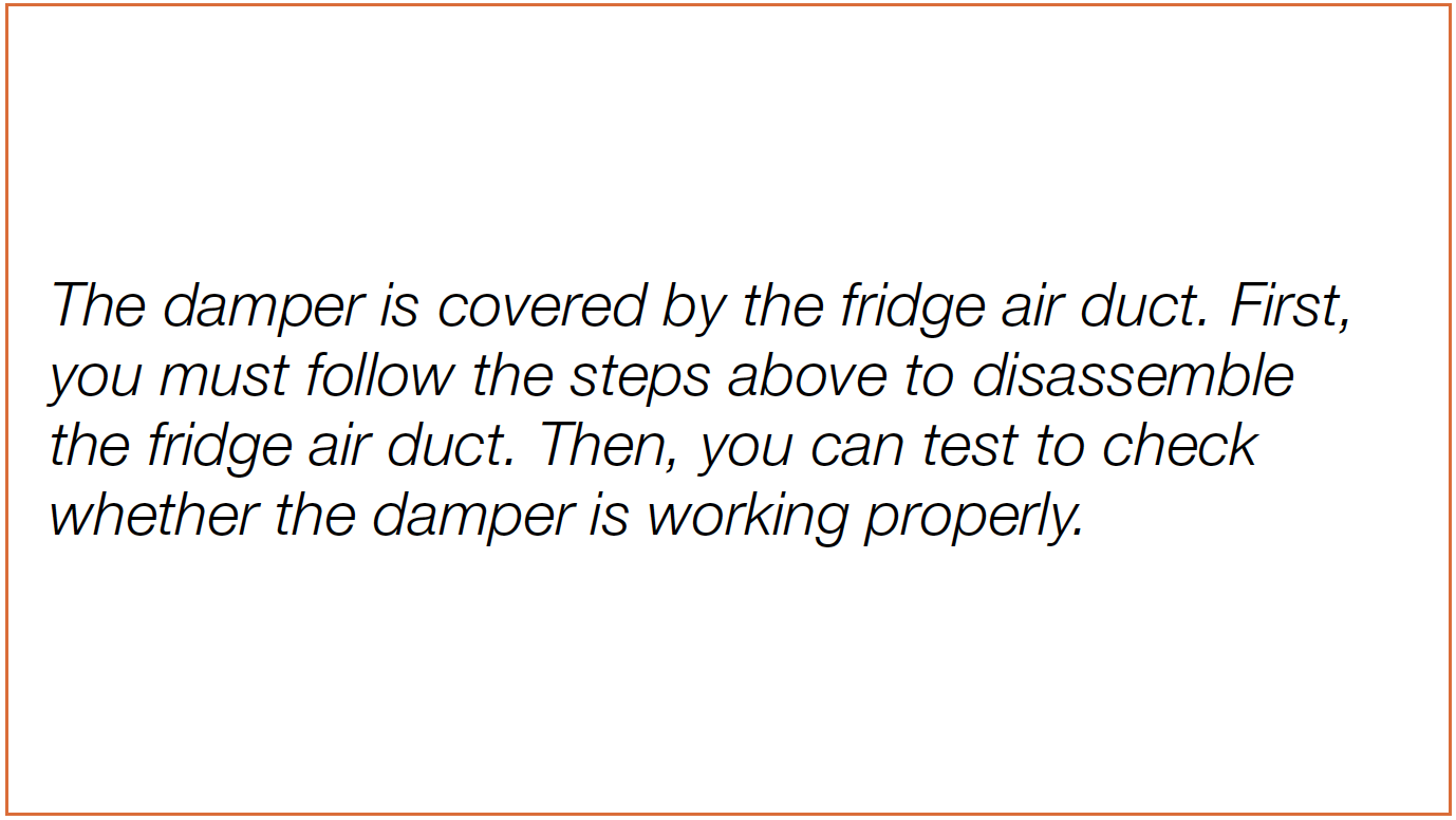

PROCEDURE 1

Step 1
Remove shelves.
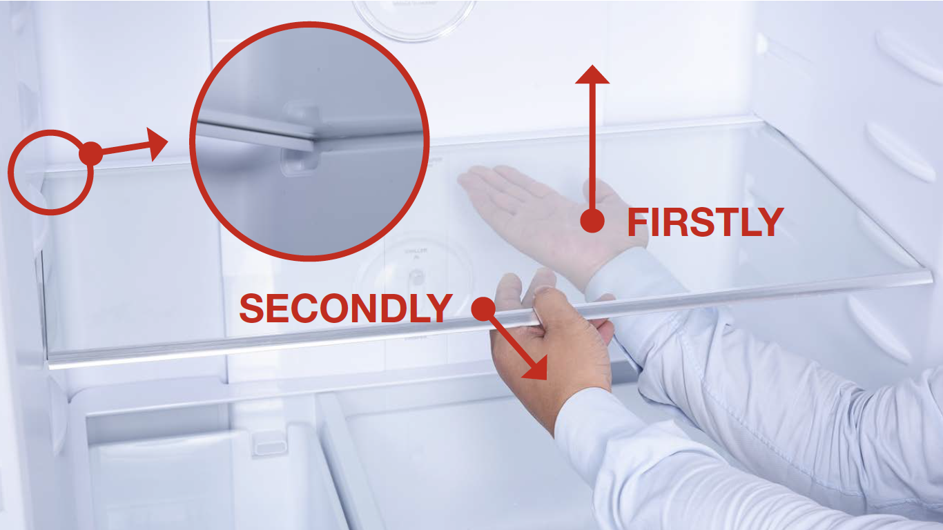
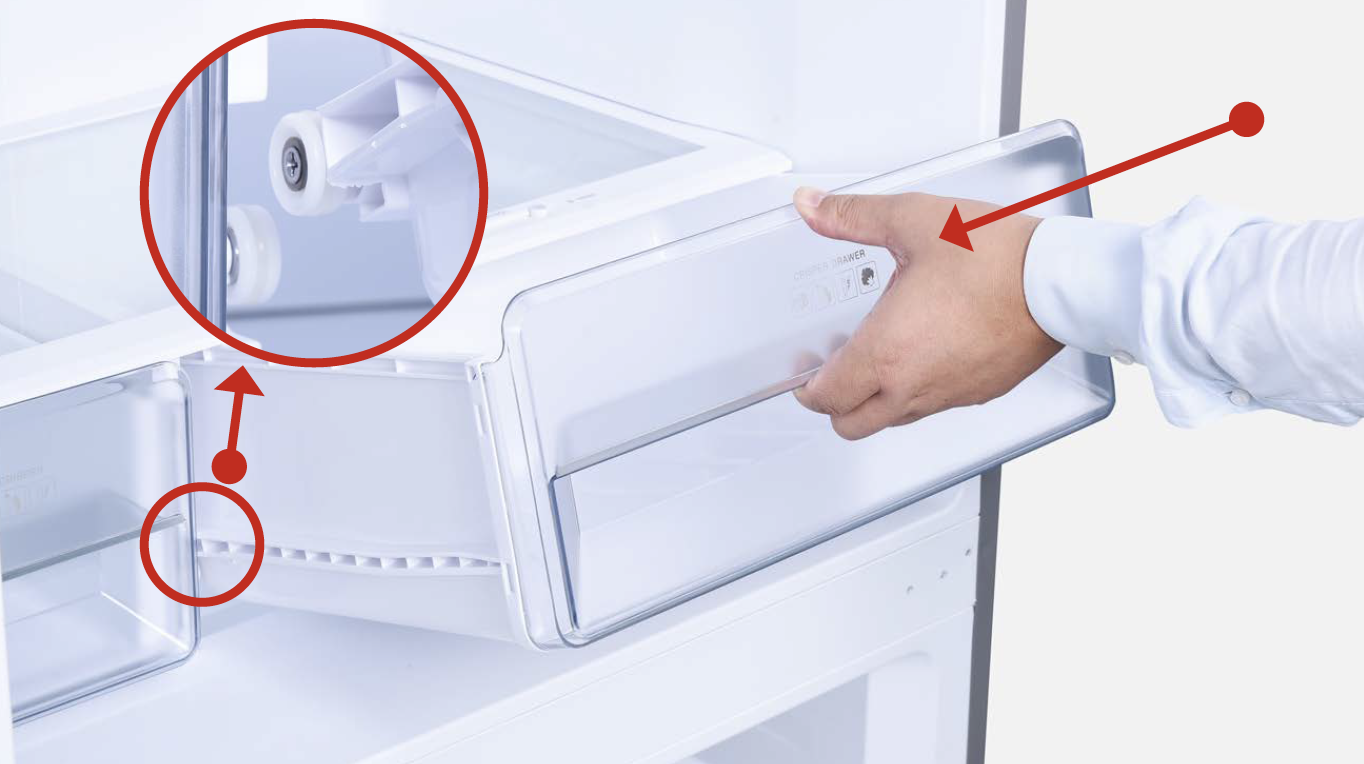
Step 2
Remove crispers.
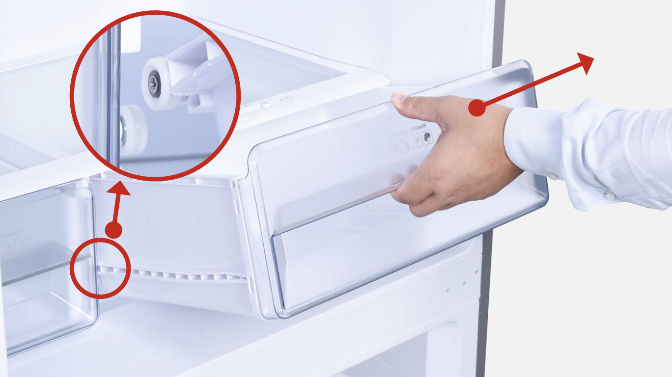
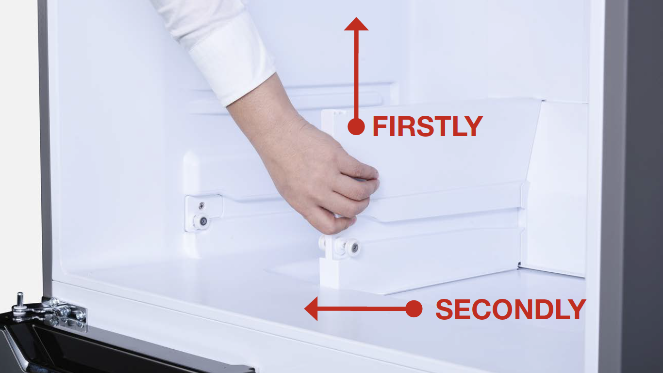
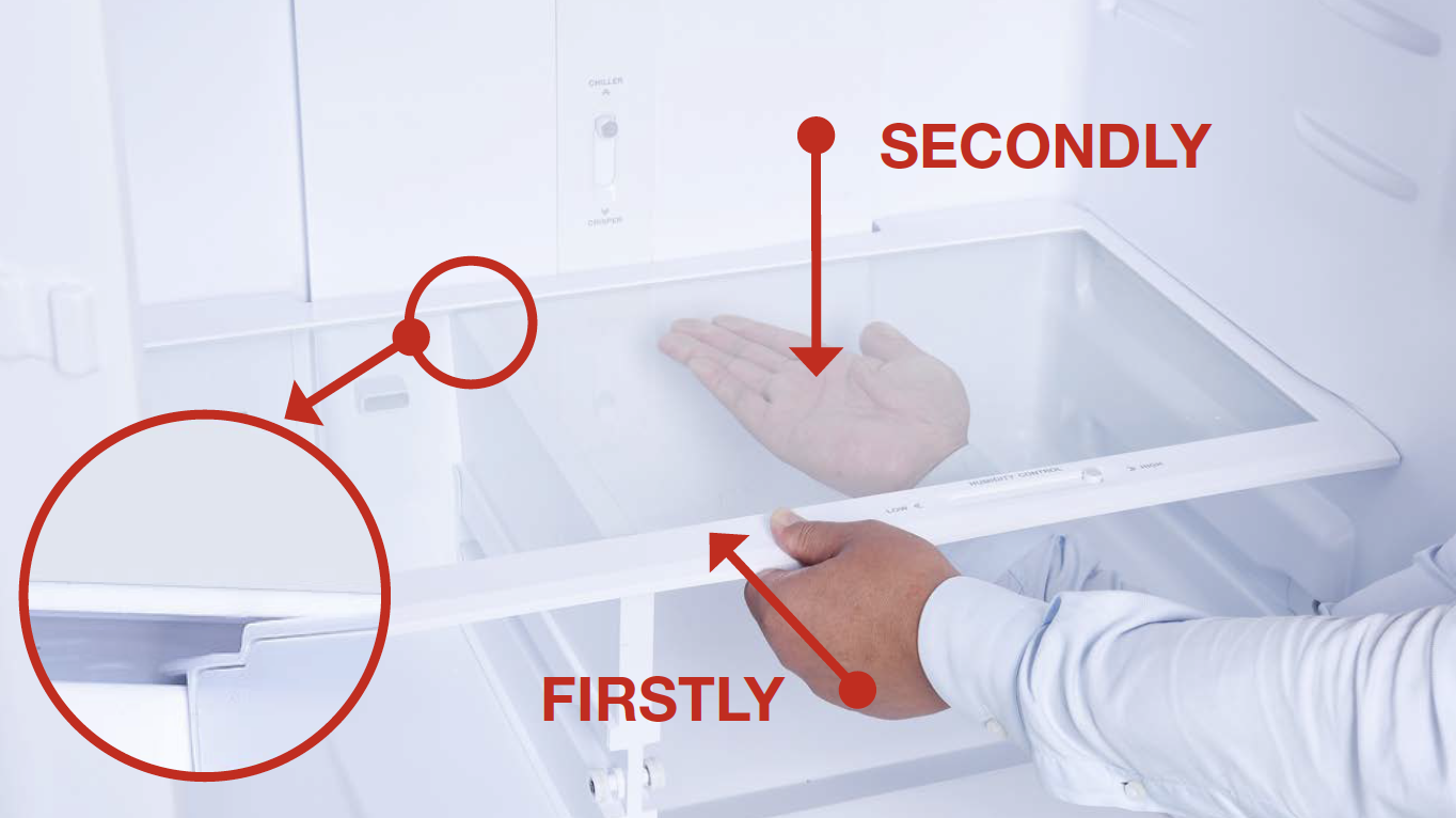
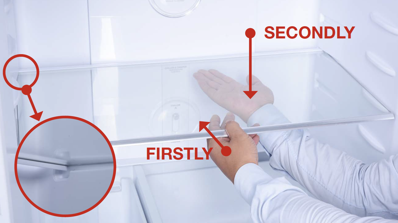
Step 3
Remove shelf cover.
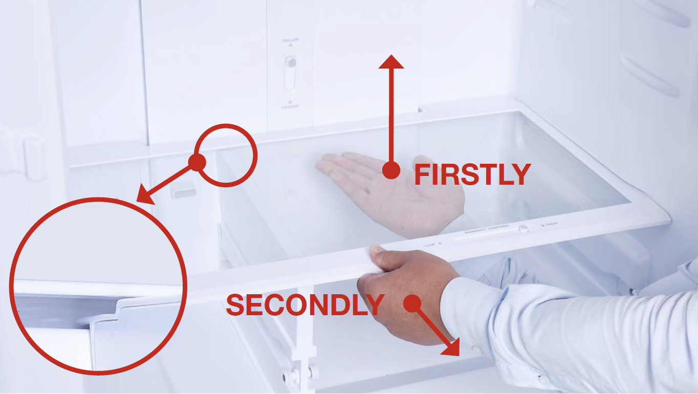
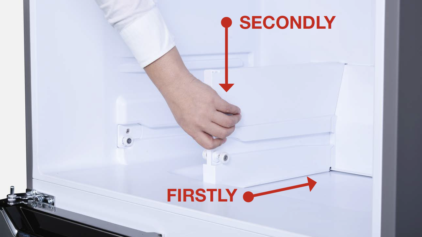
Step 4
Remove partition plate.
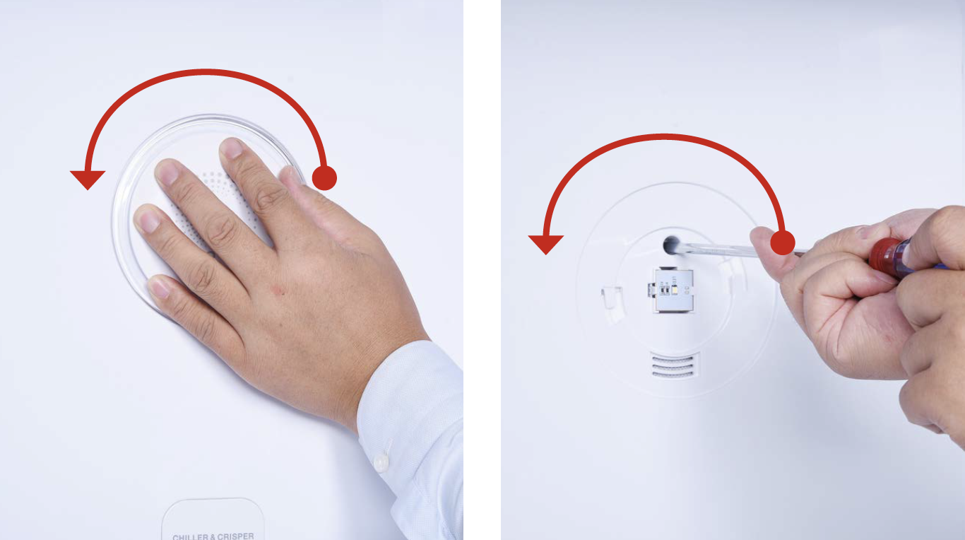
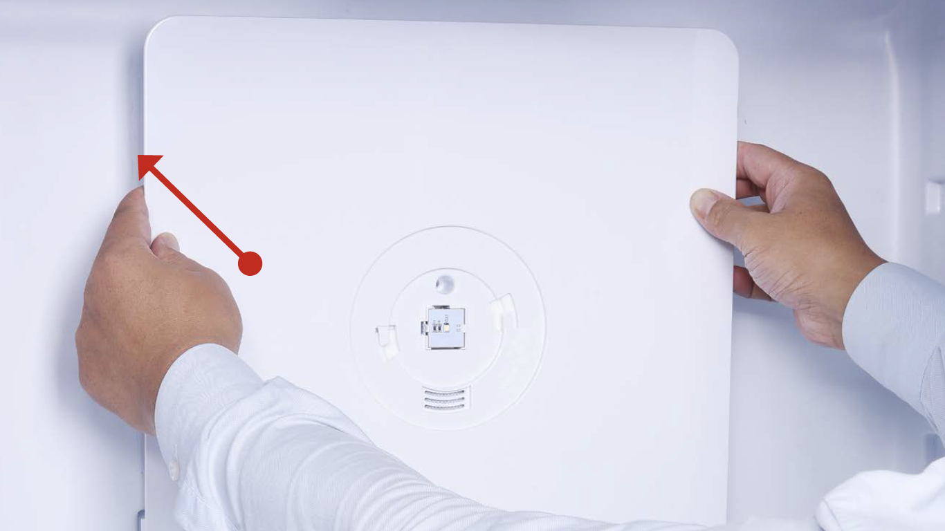
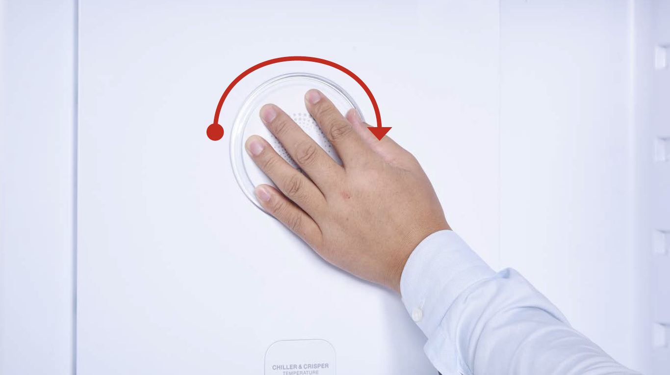
Step 5
Hold the cover and turn
in counter-clockwise
direction to loosen cover.
Then, remove cover.
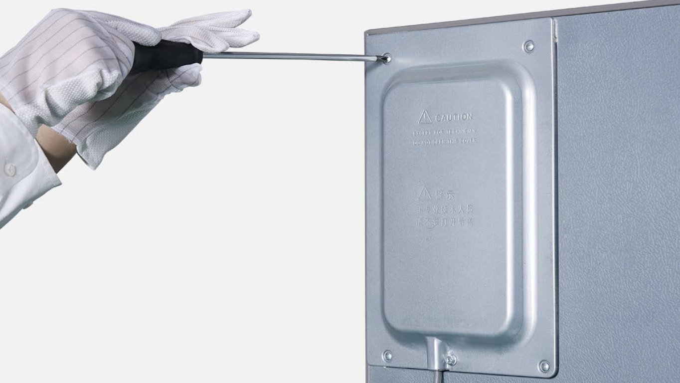
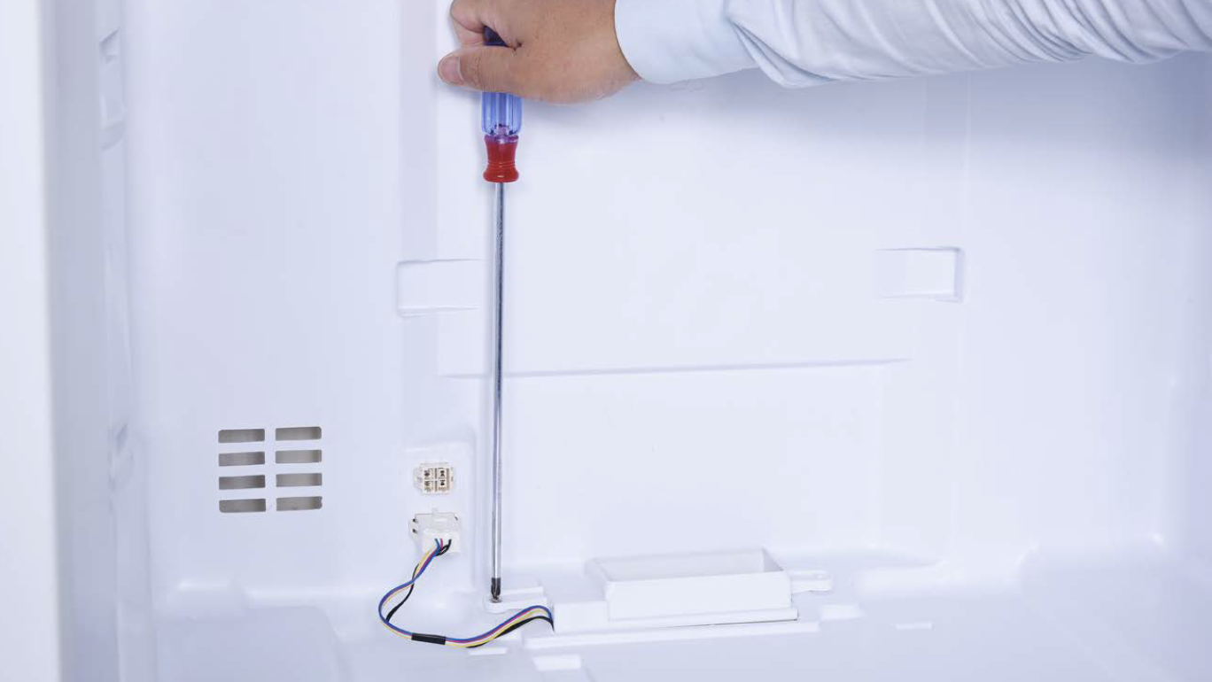
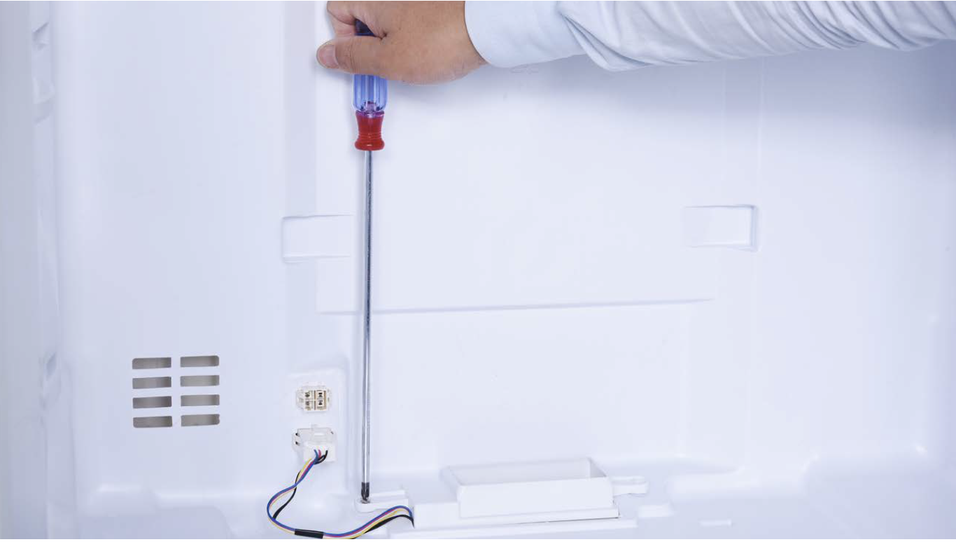
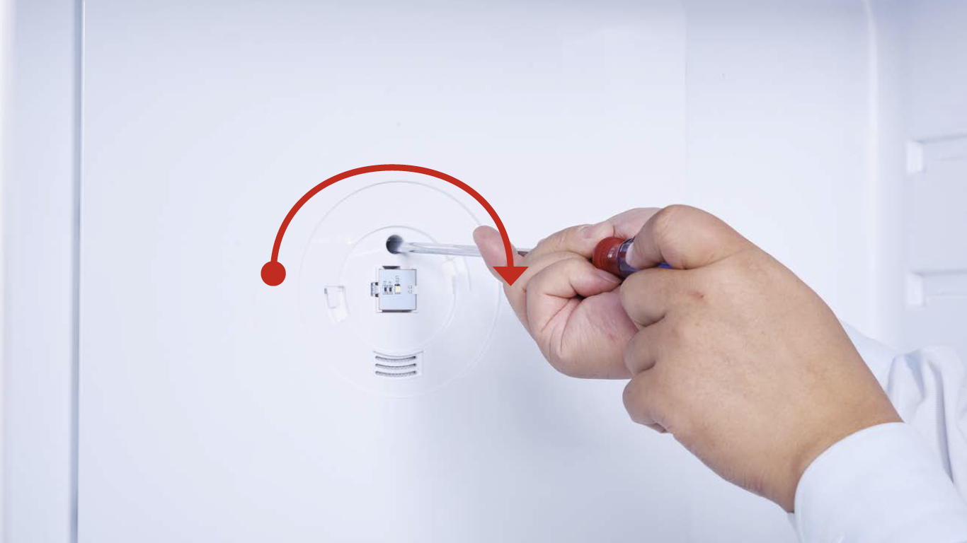
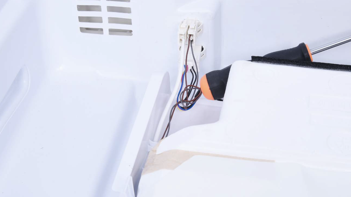
Step 6
Use 6mm cross-head screwdriver to loosen the screw in counter clockwise direction.
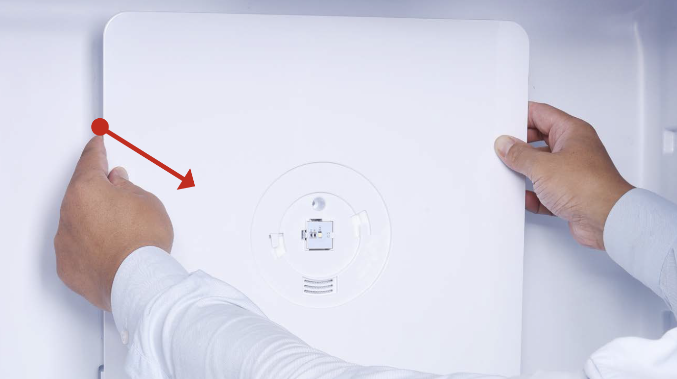
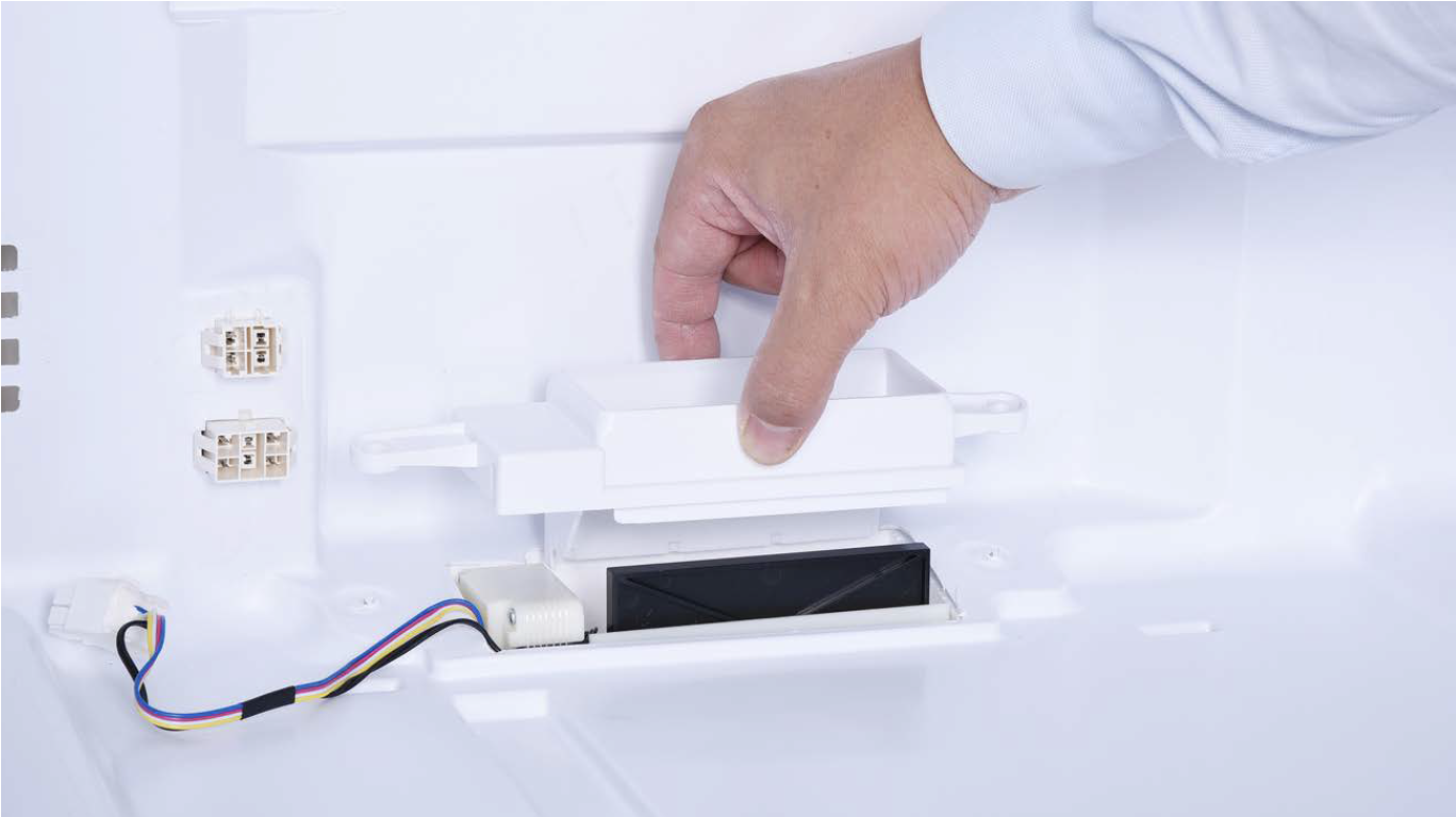
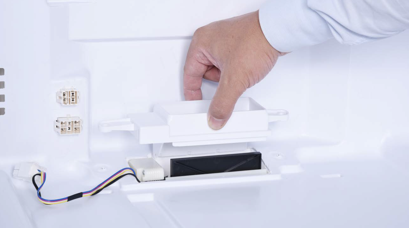
Step 7
Hold the edge of air duct to pull it out.
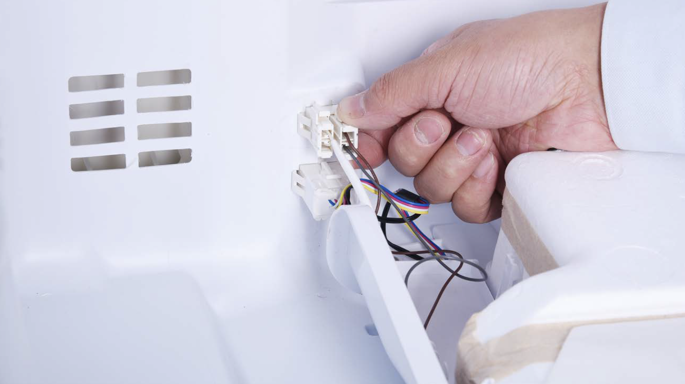
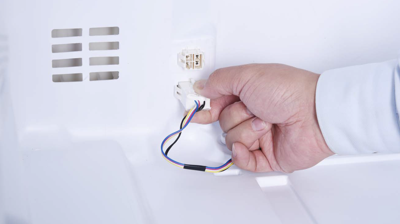
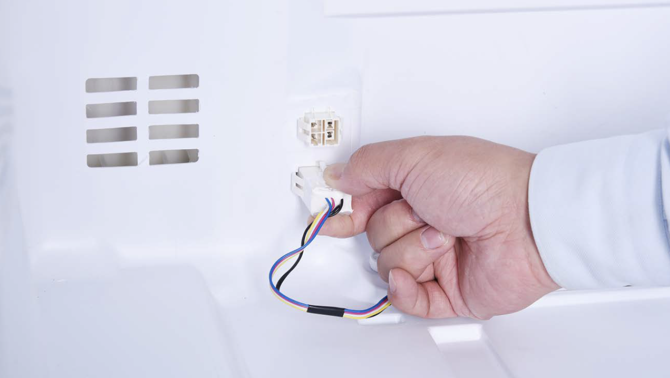
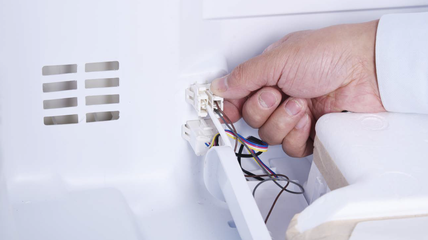
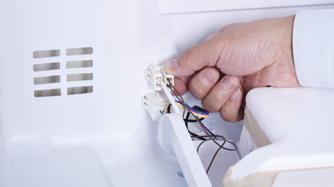
Step 8
Disconnect the terminal for fridge temp. sensor.

CHECK AND TEST 1
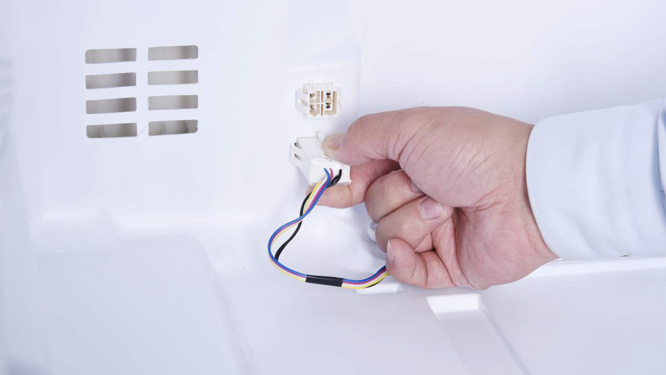
Step 1
Connect damper terminal to terminals inside fridge.

Step 2
Unscrew cover of mainboard with a cross- head screwdriver.
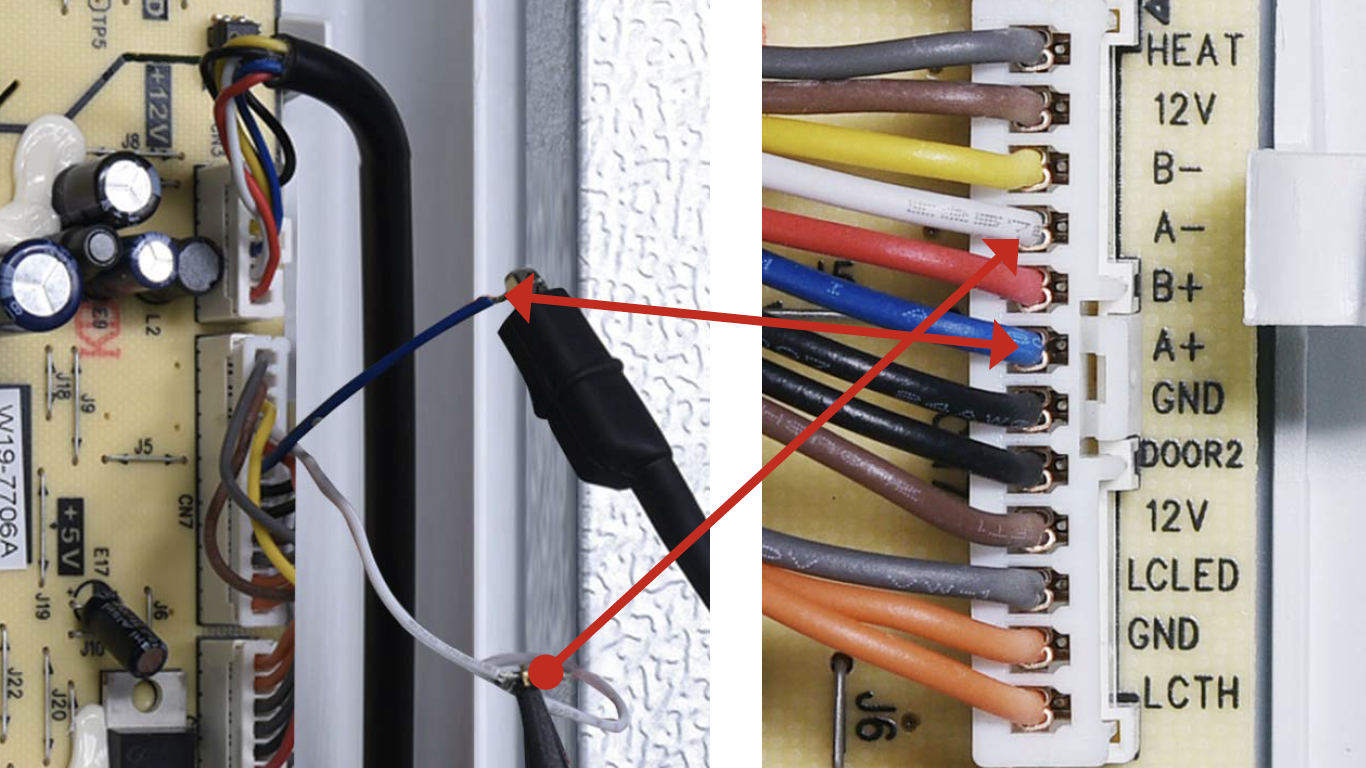
Step 3
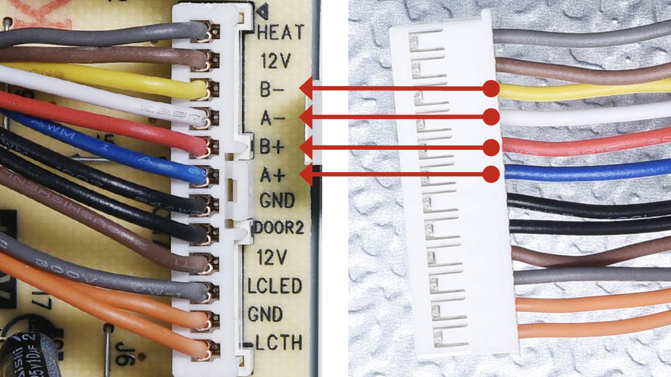
Strip off sleeves of wires in PCB area, and supply signal to damper from terminal in PCB area.

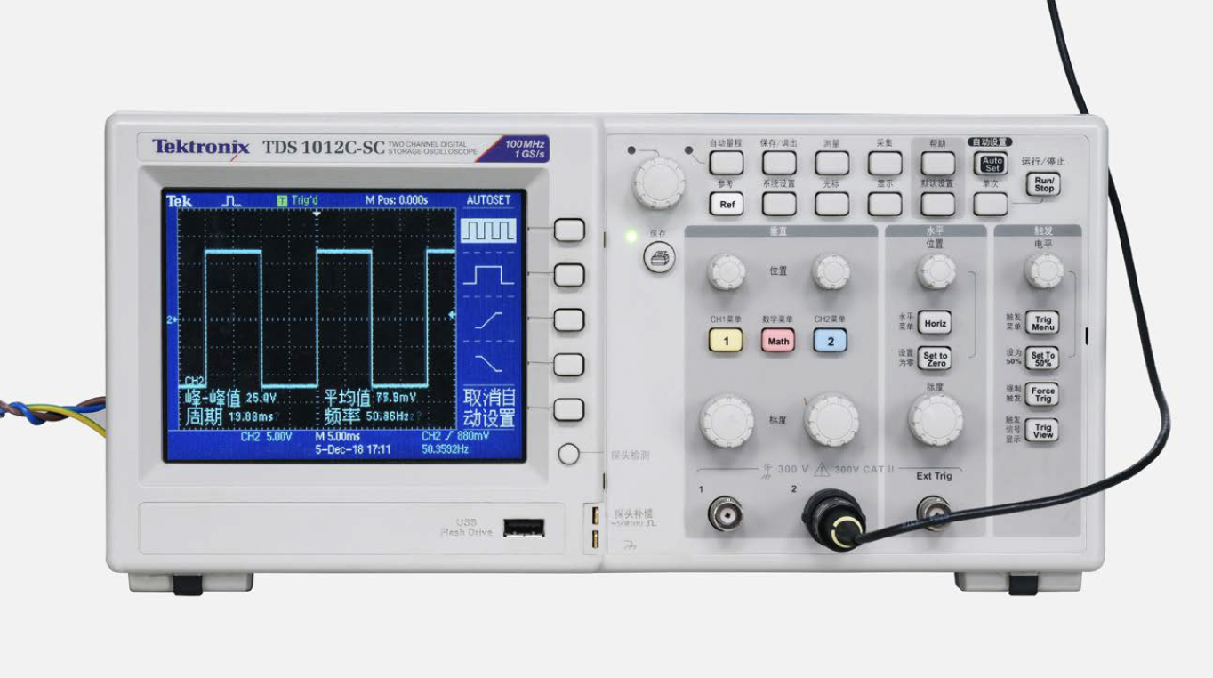
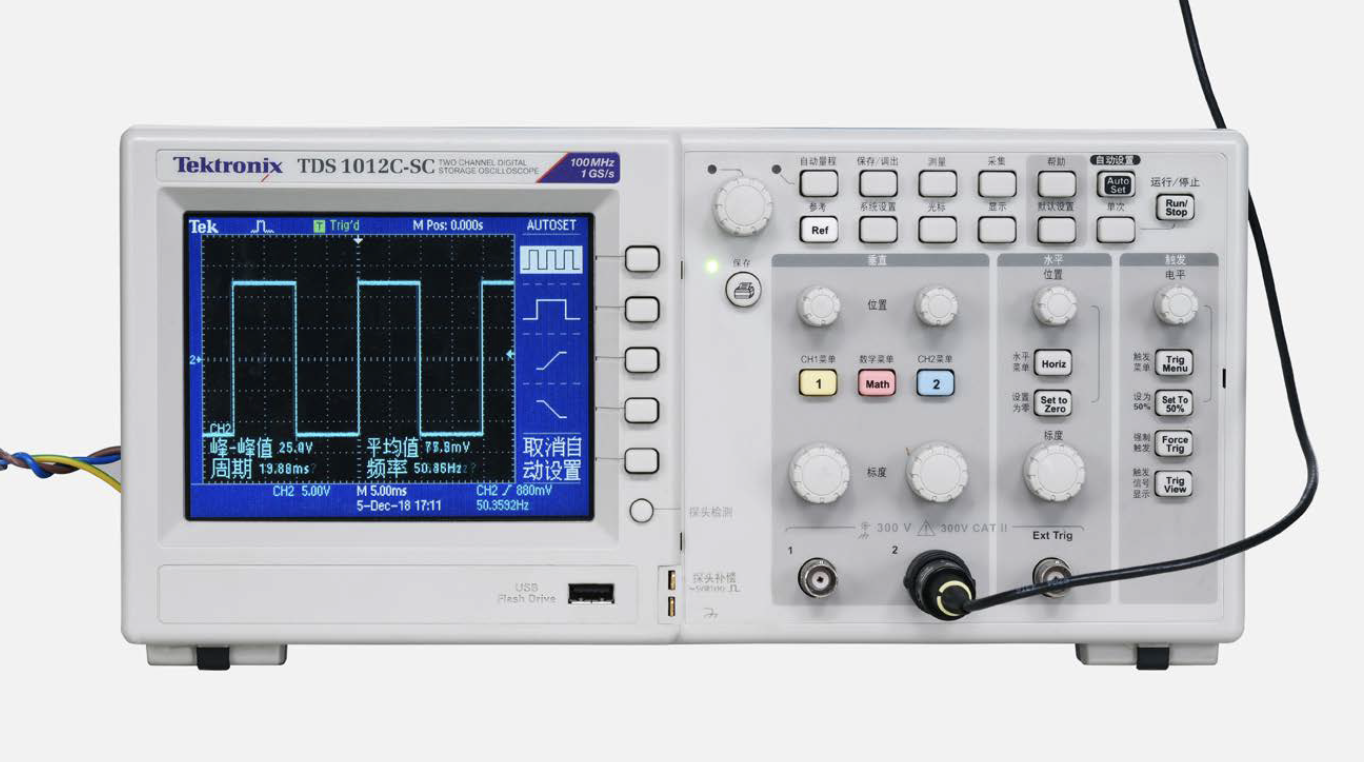
Step 4
An oscilloscope should display a square wave signal.
Step 5
See if damper door opens gradually.

DIAGNOSIS 1


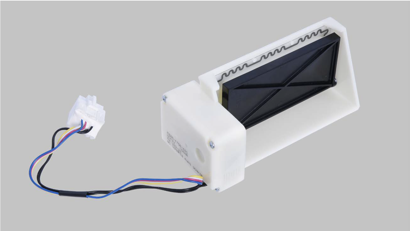
PROCEDURE 2

Step 1
Unscrew with 6mm cross-head screwdriver.
Step 2
Disconnect the terminal
Step 3
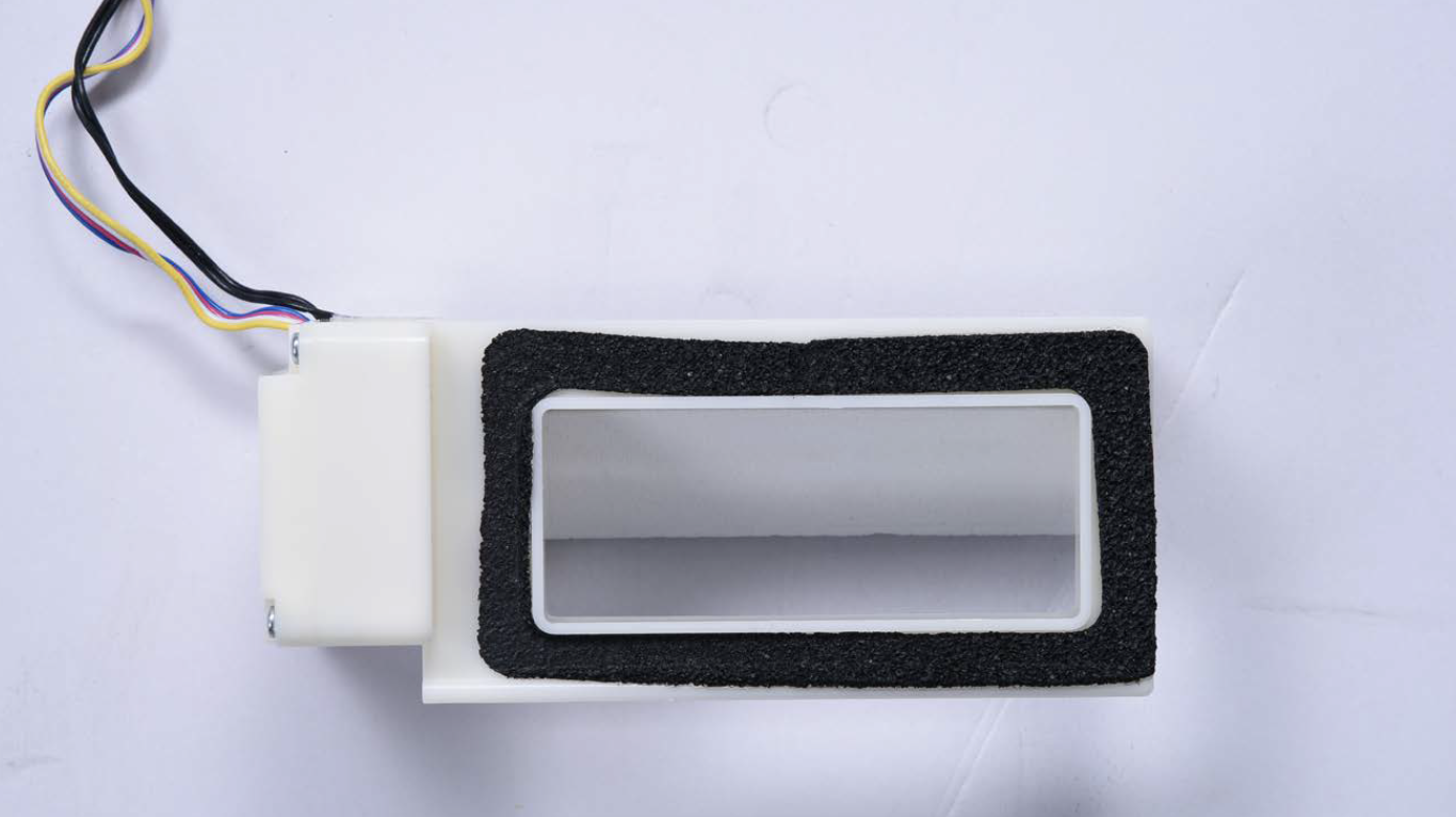
Lift the plastic cover off of the damper.
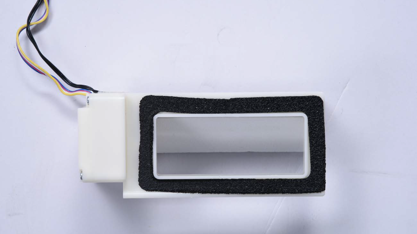
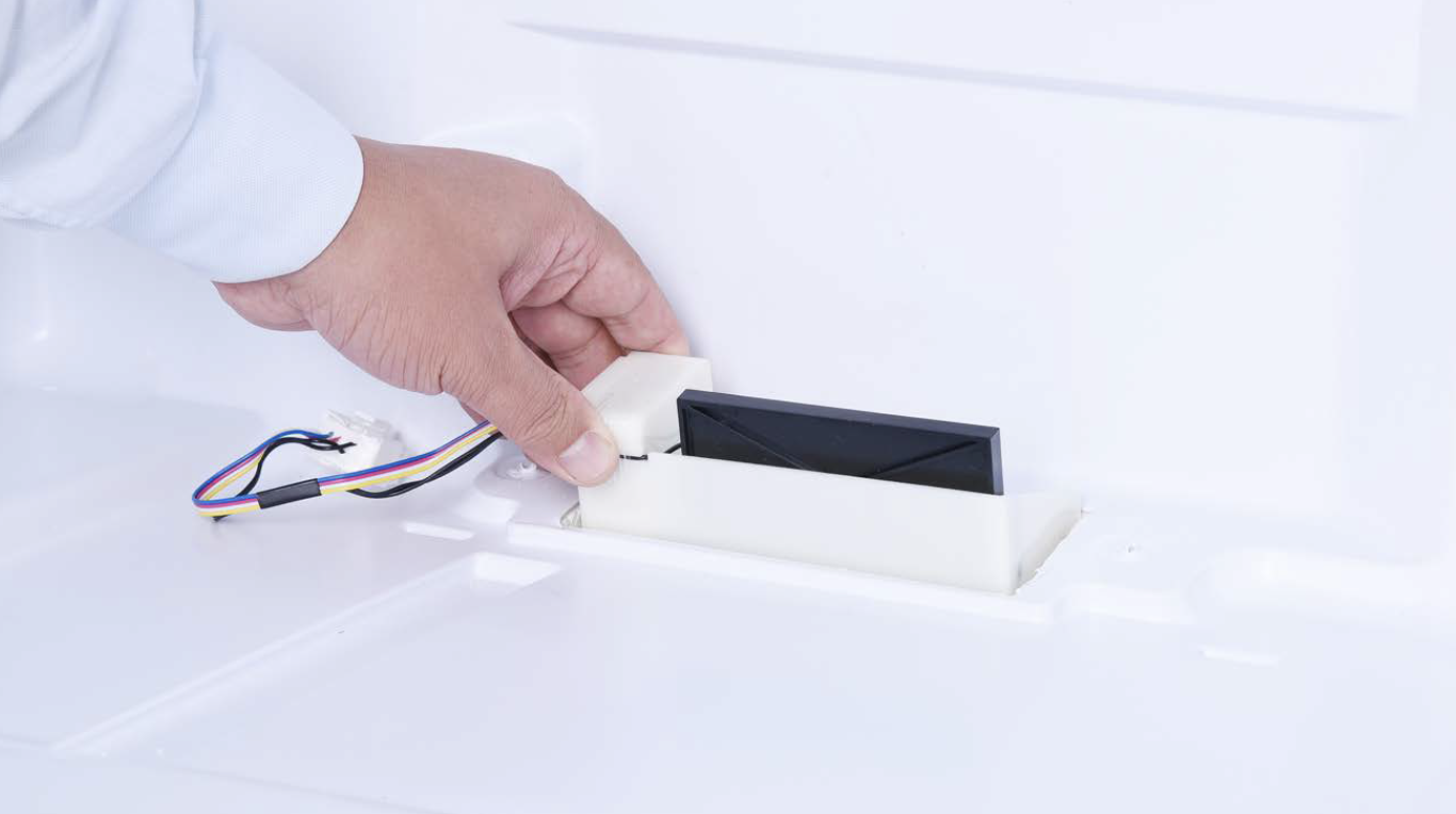
Step 4
Take damper out of air duct in foam.

CHECK AND TEST 2
Step 1
Use a standard signal producer to supply square wave to damper from terminal in fridge area.
DIAGNOSIS 2

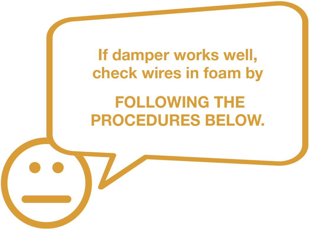

CHECK AND TEST 3
Step 1
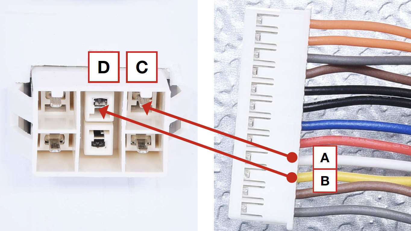
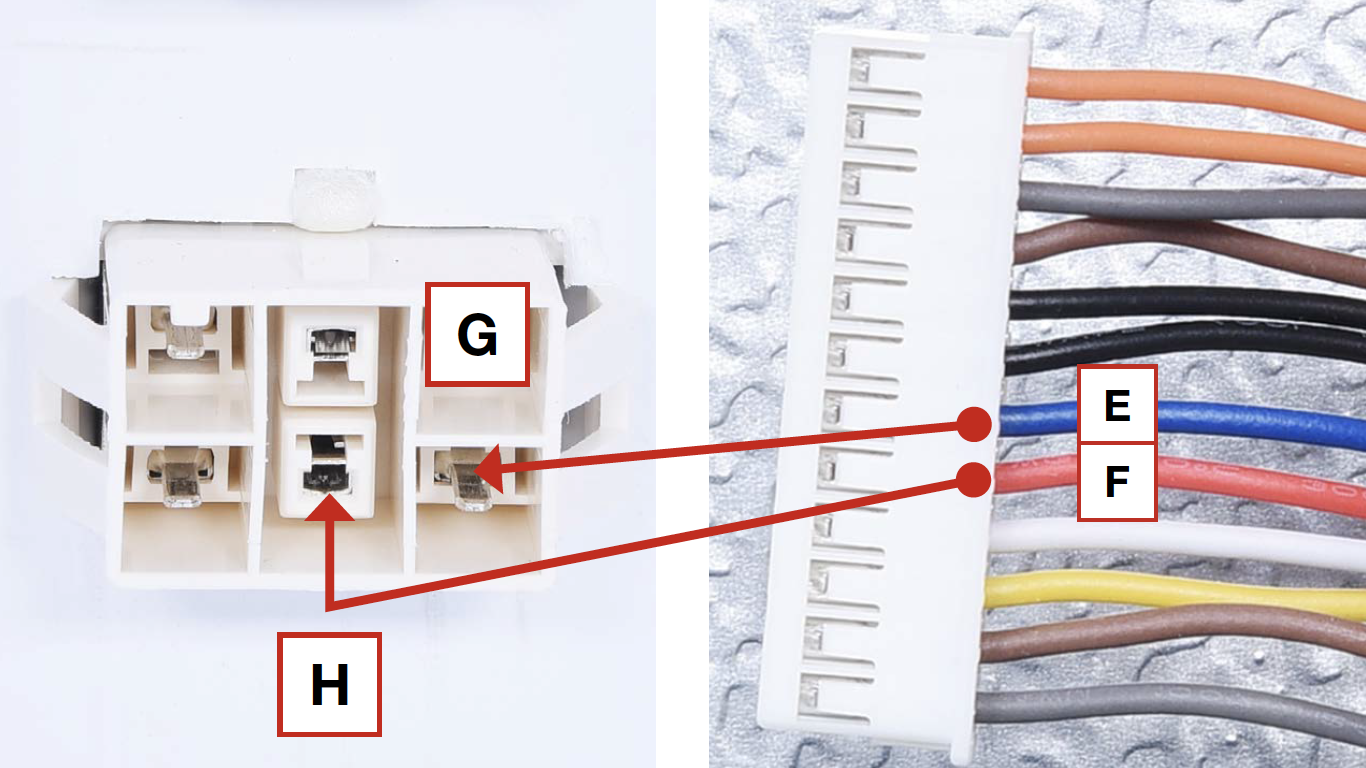
In duct area, check if terminal is pushed into final position.
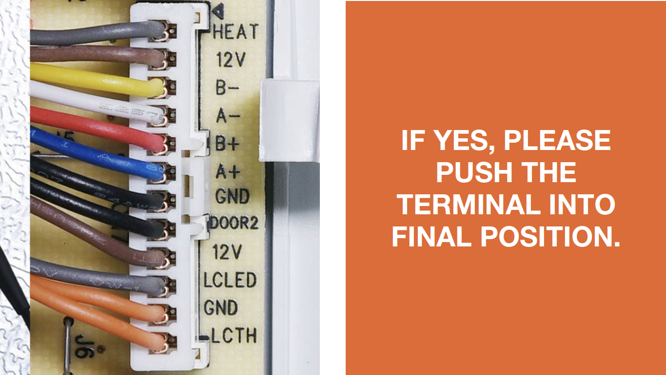
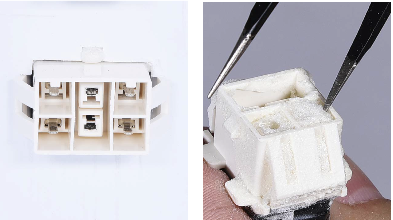
Step 2
Check if terminal is filled
with foam or not.
IF YES, please use
tweezers to clean and
remove the foam.
Step 3
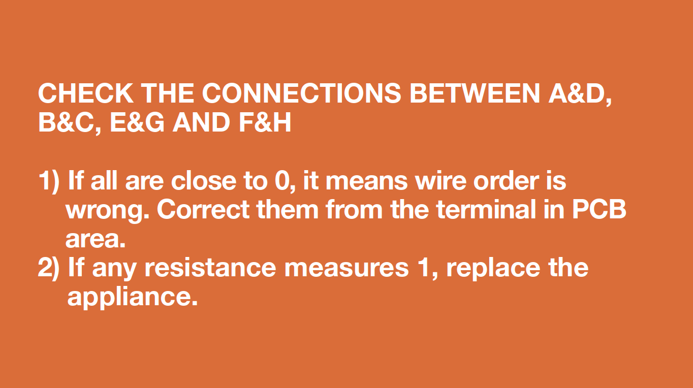
Check to ensure that wires are in proper order.
IF WIRE ORDER IS WRONG, PLEASE FOLLOW PROCEDURE 3 TO CORRECT THEM.
Step 4
Check to make sure wire
order in the foam is right
and/or see if it’s been cut H
off.
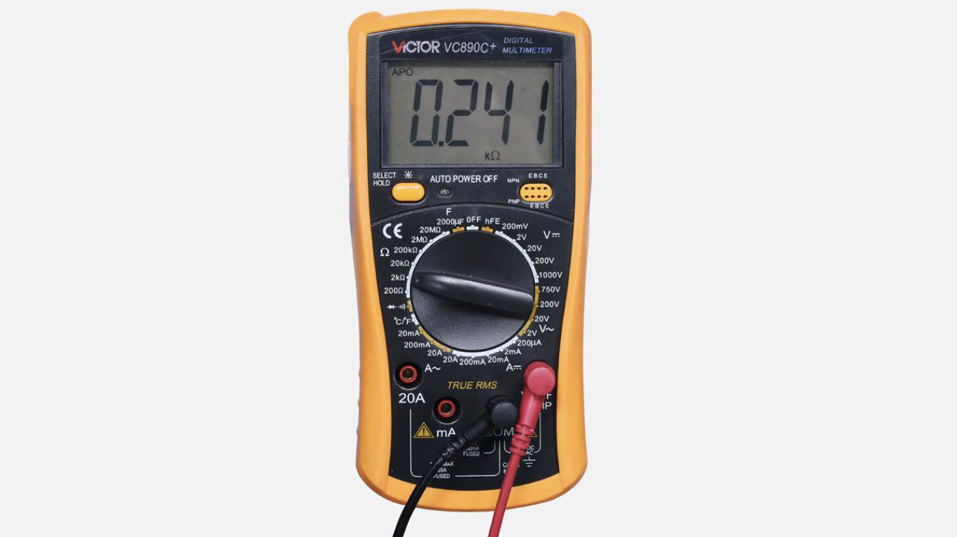
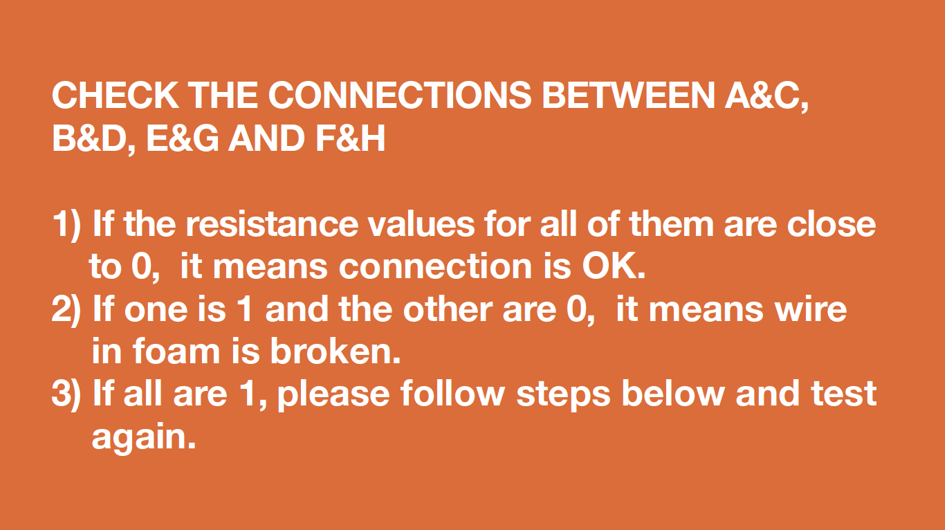
Step 5
Use multimeter to test
connections.
a. Put detector into one
end of wires in PCB
area;
b. Put another detector
into end of wires
behind air duct.
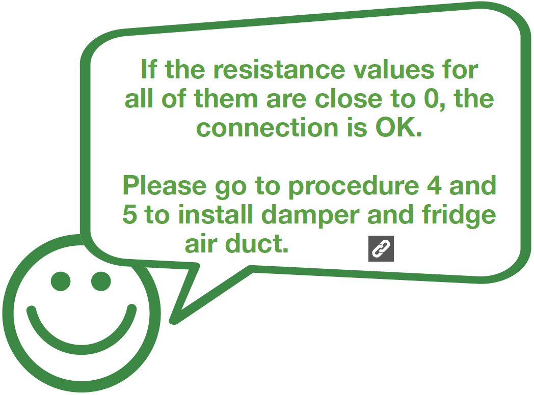
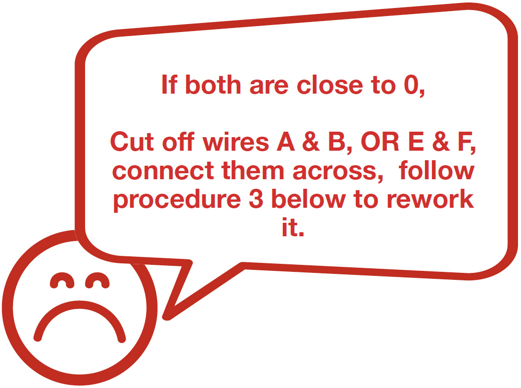
DIAGNOSIS 3
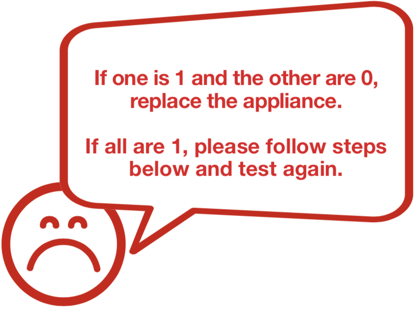
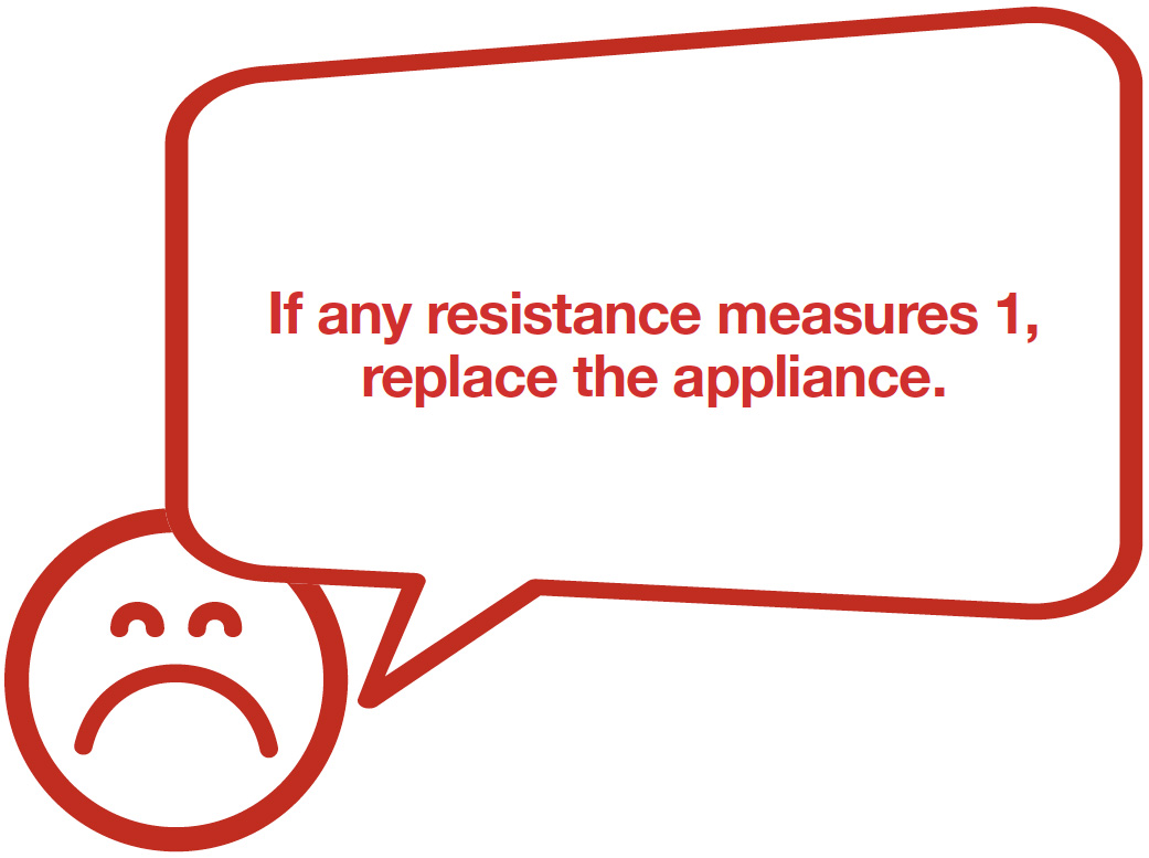
DIAGNOSIS 4
Note
PROCEDURE 3

Step 1
Cut the wire
Step 2
Peel off the sleeves.

Step 3
Check to ensure proper wire order and reconnect them.

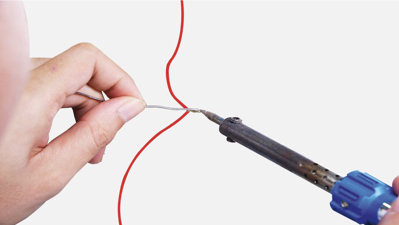
Step 4
Tin soldering.
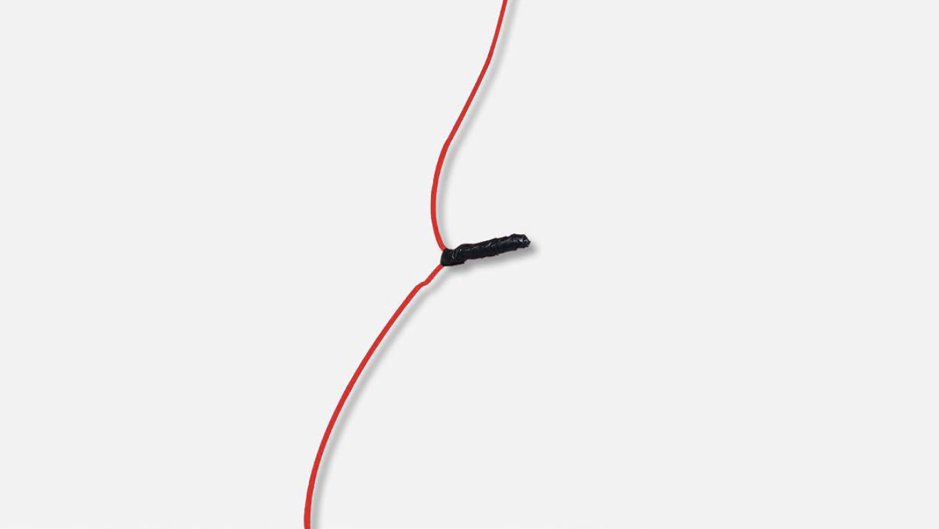
Step 5
Cover connecting point with electrical tape.
CHECK AND TEST 4
Step 1
Connect damper terminal to terminals inside fridge.
Step 2
Strip off sleeves of wires in PCB area, and supply signal to damper from terminal in PCB area.
Step 3
An oscilloscope should display a square wave signal.
Step 4
See if damper door opens gradually.
DIAGNOSIS 5


PROCEDURE 4

Step 1
Put damper into air duct in foam.

Step 2
Put the plastic cover on top of damper.
Step 3
Connect the terminal.
Step 4
Screw with 6mm cross-head screwdriver.
PROCEDURE 5
Step 1
Re-connect the terminals.
Step 2
Hold air duct by edges to put it back in place.
Step 3
Use a 6 mm cross-head screwdriver to tighten the screw clockwise.
Step 4
Hold the cover and turn it clockwise to tighten the lid, then move it backwards.
Step 5
Insert partition plate.
Step 6
Insert shelf cover.
Step 7
Insert crispers.
Step 8
Insert shelves.
TIPS DURING INSTALLATION PROCEDURES FOR FRIDGE AIR DUCT.
Tip 1
Connect the terminals.
Tip 2
Push terminals into place, then move wires to prevent crushing of wires with edge of air duct.
Tip 3
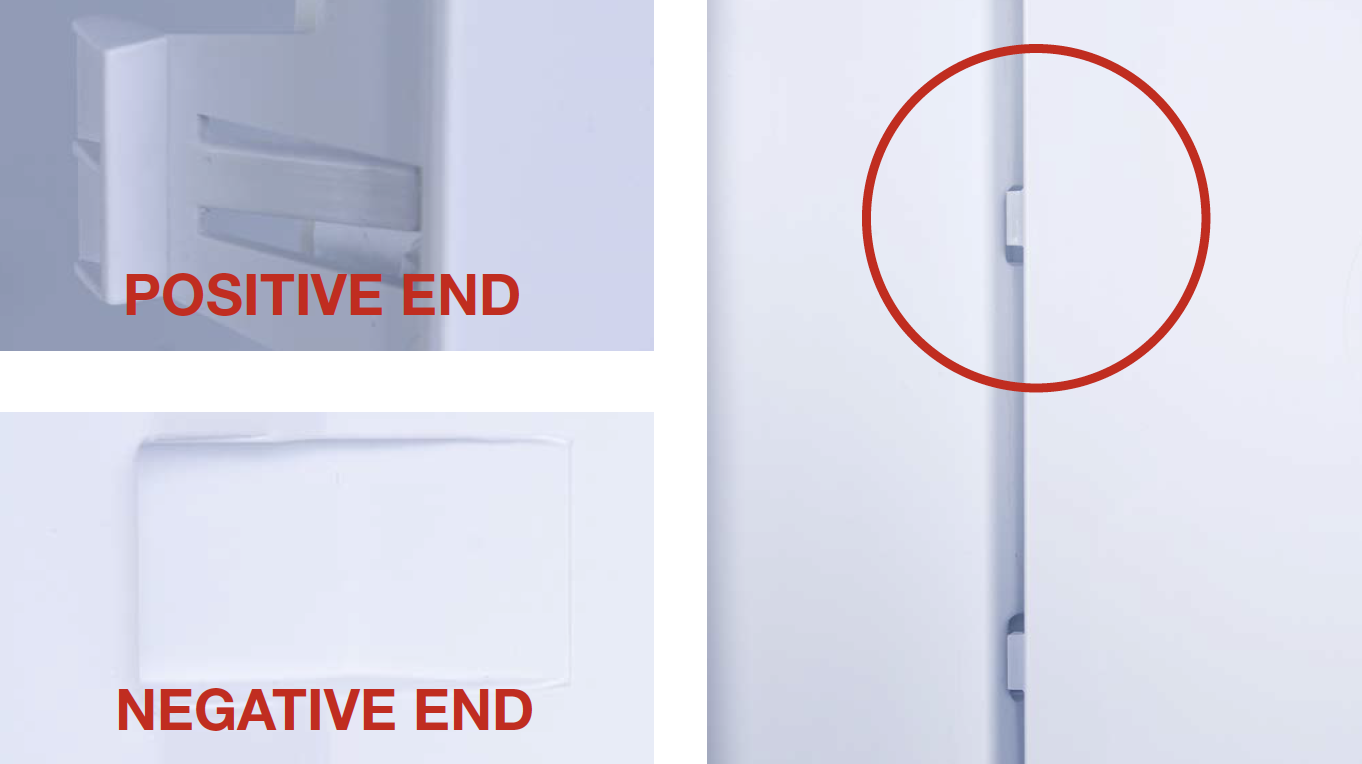
When reinstalling the air duct, first insert positive shaft into the negative hole.
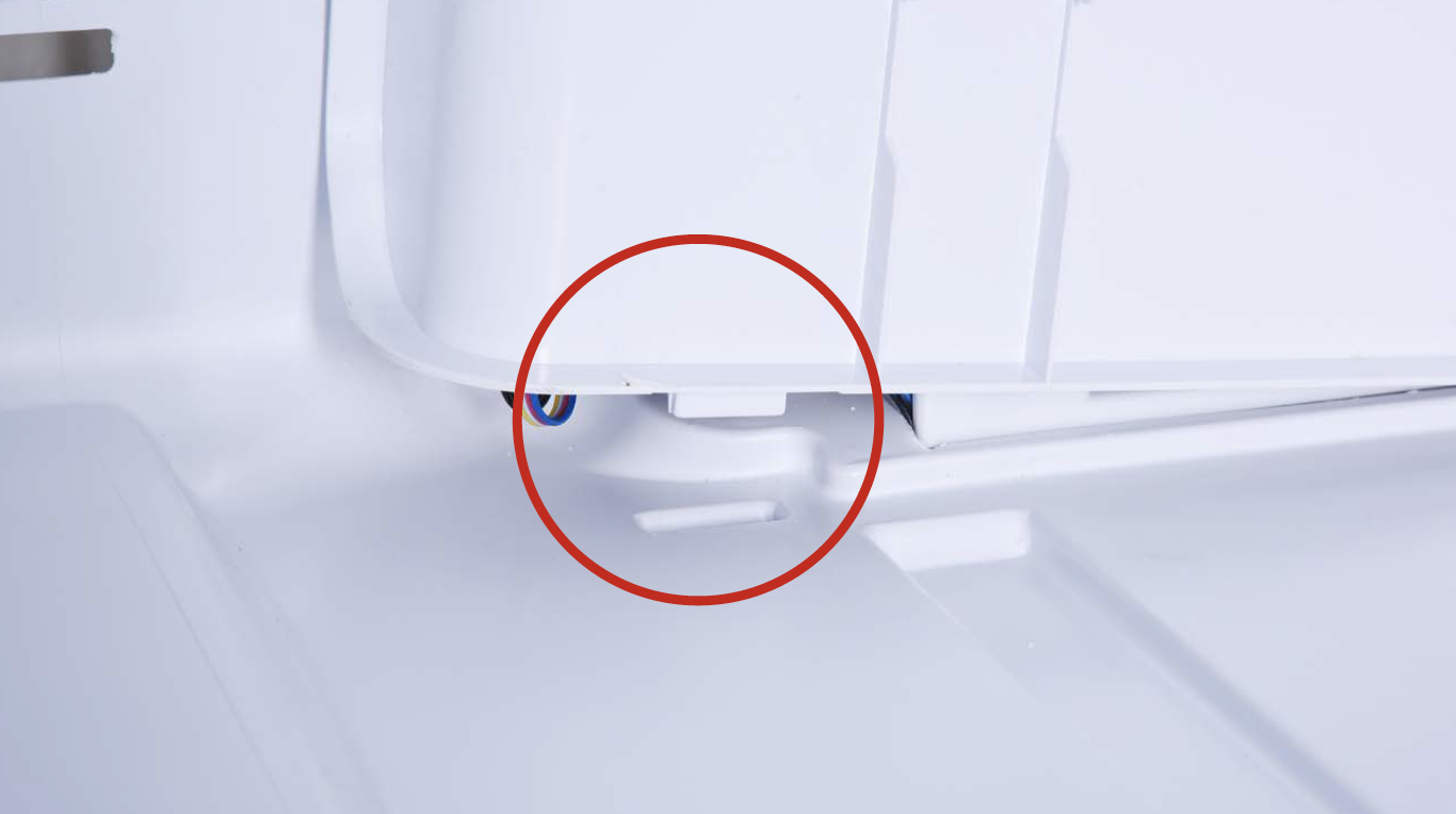
Tip 4
Then, fasten the clasp on top using the same method.

DIAGNOSIS 6
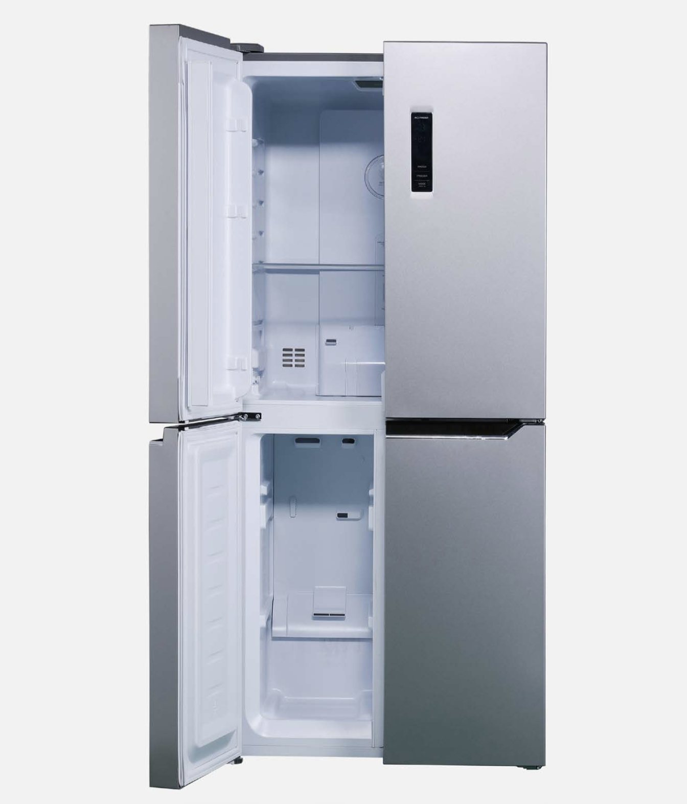
Step 1
Power on the appliance, then open the doors on the same side to the same degree, wait 5 seconds, and put your hand in front of fridge air duct outlet to verify.


GO BACK TO COMPONENT LIST