


CHECK AND TEST 1
Step 1
Unscrew cover of mainboard with a cross-head screwdriver.

Step 2
Disconnect terminals.

Step 3
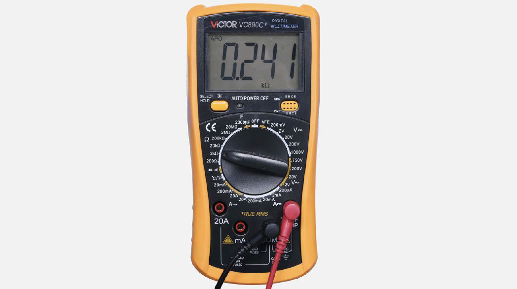
Measure resistance of heater from terminal in PCB area.

Step 4
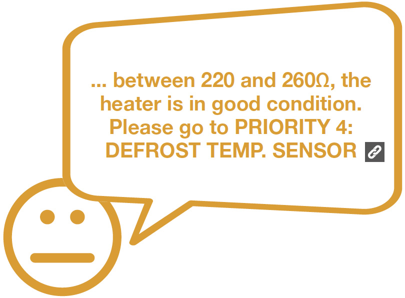
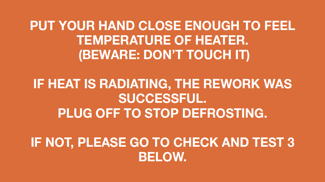
Check the result.

DIAGNOSIS 1


PROCEDURE 1
Step 1
Remove all drawers.

Step 2
Remove all shelves.

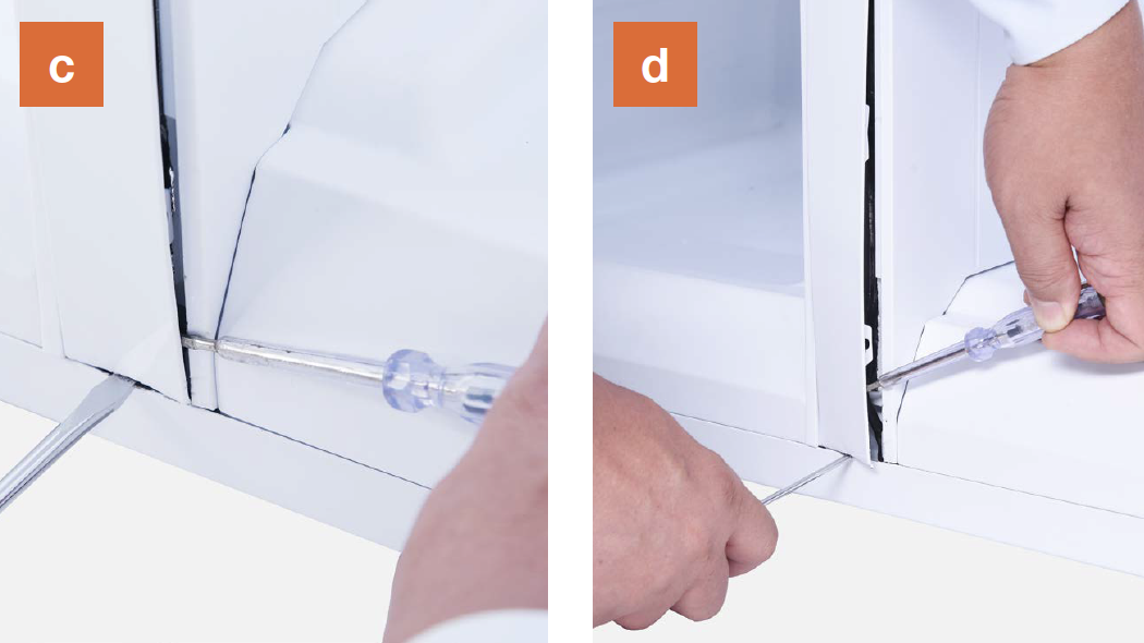
Step 3
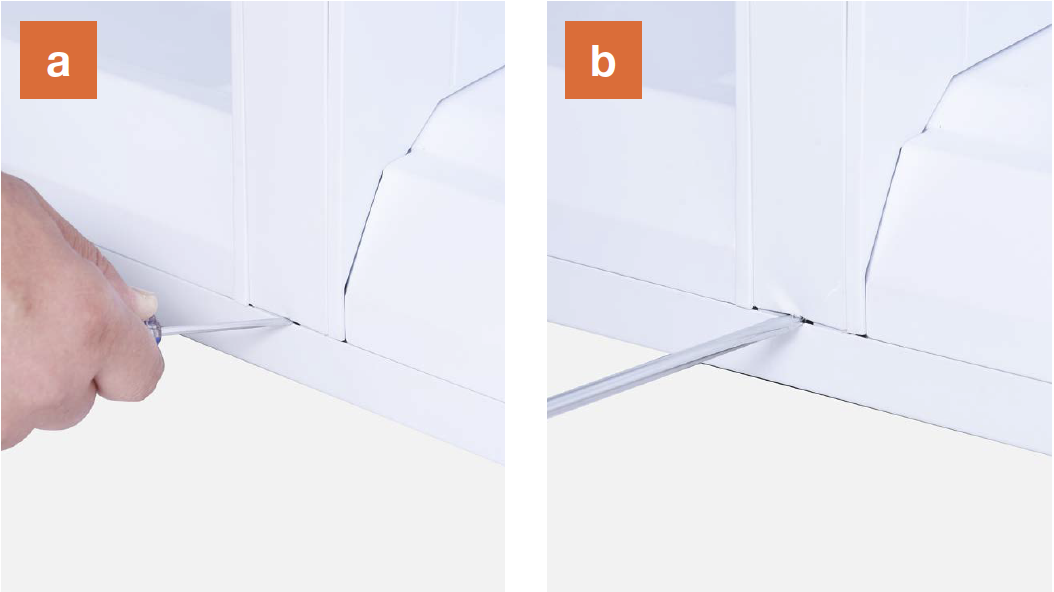
Remove the vertical
partition plate:
a. Insert 2mm slotted
screwdriver into
the gap;
b. Lever up the cover
plate from bottom;
c. Insert 2mm slotted
screwdriver into the
side gap;
d. Lever up the cover
plate from bottom;
e. Pull the bottom end of
cover out;
f. Pull the top of the
cover out;

g.Take pipes out and pull them into a
horizontal position;
h. Push the latch down
and lift top out of
cavity;

i. Push latch up and pull bottom out of cavity;

j. Pull partition outward and remove partition.

k. View of interior after partition has been removed.

Step 4
Dismantle the air duct.
a. Hold the bottom of air duct;
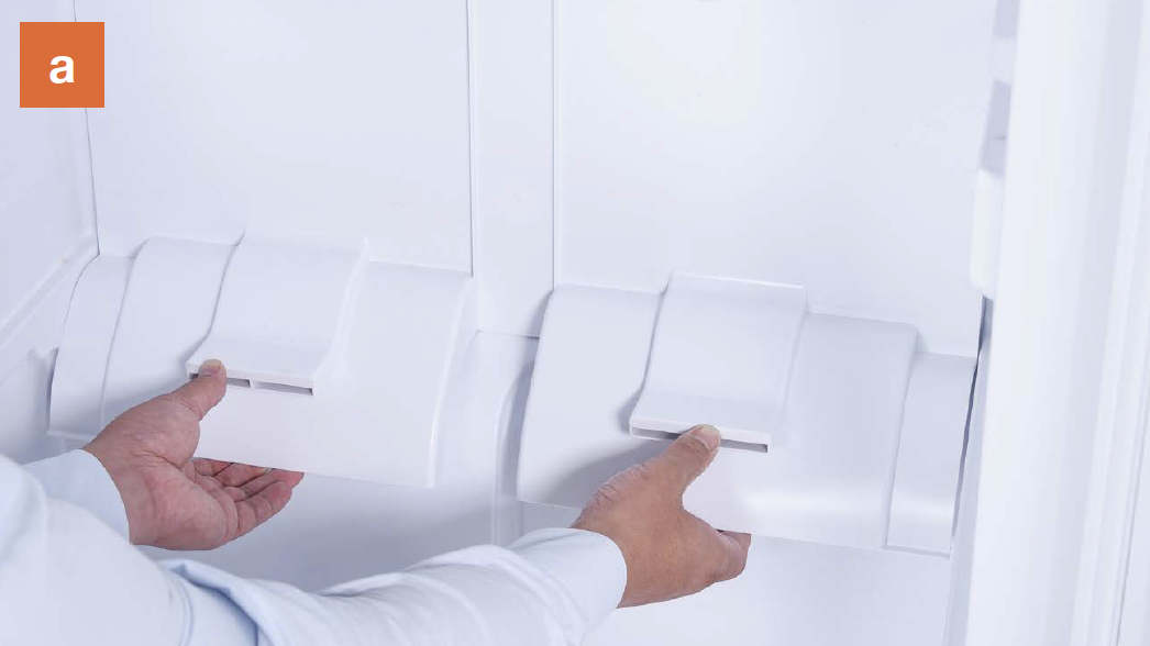
b. Pull air duct out from below;

d. Disconnect the
terminal of freezer
temp. sensor;

e. Remove air duct.

CHECK AND TEST 2
Step 1
testo testoIf yes, use tweezers to remove foam.

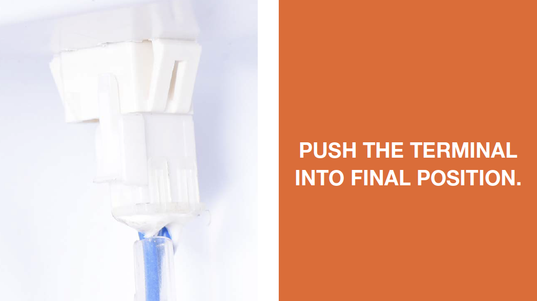
Step 2
Ensure terminals behind freezer air duct are properly inserted.
Step 3
Connect terminals with mainboard.

Step 4
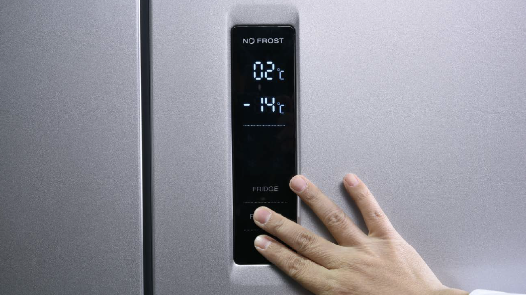
Press Freezer Temp. button along with Mode button for 5 sec, “0” flashes in freezer temperature area.

Step 5
Press Freezer
Temperature button,
1 and 3 will appear in
freezer temperature area.

Step 6
When 3 appears, remove finger and select manual defrost

DIAGNOSIS 2
CHECK AND TEST 3
Step 1
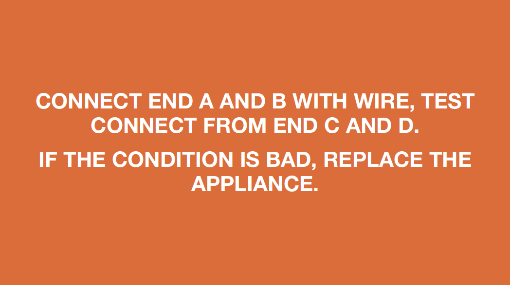
Use wire to connect the 2 ends of terminal behind freezer air duct.

Step 2
Use multimeter to check whether the connection of wires is good or not.

DIAGNOSIS 3

CHECK AND TEST 4
Step 1
Check if wires for defrost heater are broken or not.

DIAGNOSIS 4
PROCEDURE 2

Step 1
Cut off the wire.

Step 2
Peel off the sleeves.
Step 3
Ensure proper wire order and connect.

Step 4
Tin soldering.

Step 5
Cover point of connection with electrical tape.

CHECK AND TEST 5
Step 1
Measure the resistance of heater from terminal in freezer.

DIAGNOSIS 5


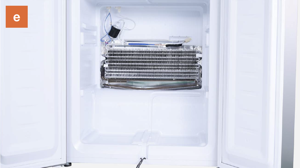
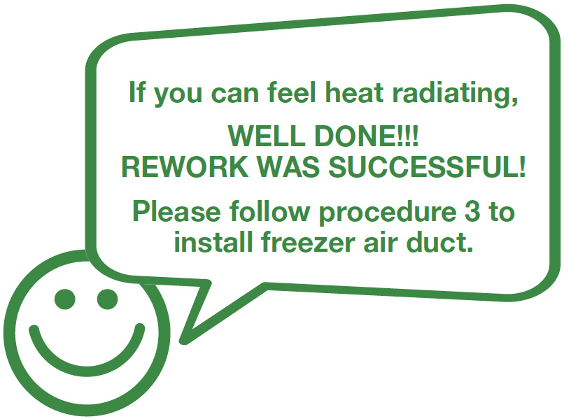
PROCEDURE 3

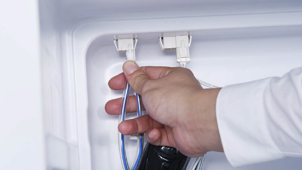
Step 1
Disconnect the terminals of heater.
Step 2
Use screwdriver to remove the heat conductor.

Step 3
Use 6mm cross-head screwdriver to unscrew on the right and left sides.

Step 4
Lift evaporator and heater up 20mm. The bottom of refrigerator must be higher than the edge of water trough.

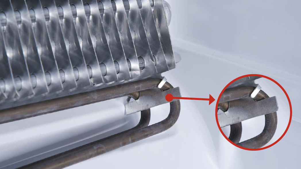
WARNING!
Be careful not to deform pipes in red square during step 4.

Step 5
Loosen the clips for fastening heater. There are 8 clips in total.
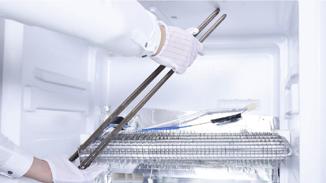
Step 6
Remove the heater.
REVERSE THE ABOVE PROCESS TO REINSTALL THE HEATER
CHECK AND TEST 6
Step 1
Reconnect all terminals behind freezer air duct.

Step 2
Connect terminals with mainboard.

Step 3
Press Freezer Temp. button along with Mode button for 5 sec, “0” flashes in freezer temperature area.
Step 4
Press Freezer
Temperature button,
1 and 3 will appear in
freezer temperature area.

Step 5
When 3 appears, remove finger and select manual defrost.

DIAGNOSIS 6

PROCEDURE 4
Tip 1
When re-installing the air duct, move the wires out of the way so that they won’t be crushed by air duct.

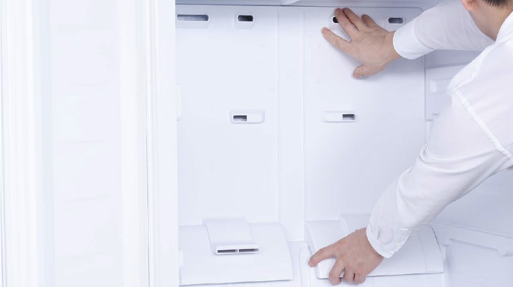
Tip 2
After pushing the air duct into its position, there should be a sound of click. If no, redo it again.
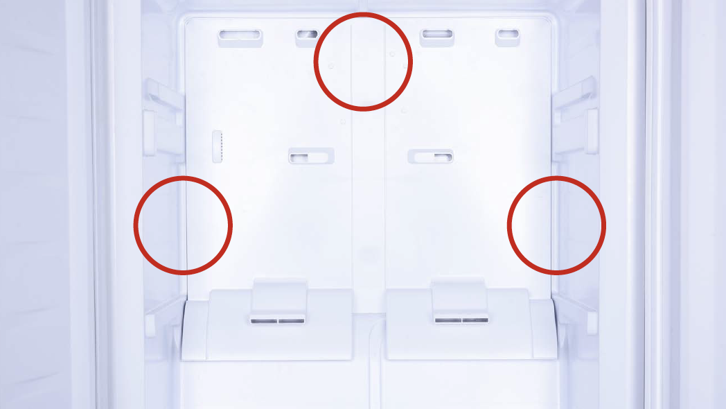
Tip 3
Check to see if there is
a wide gap between air
duct and cabinet.
IF SO, install air duct
again.
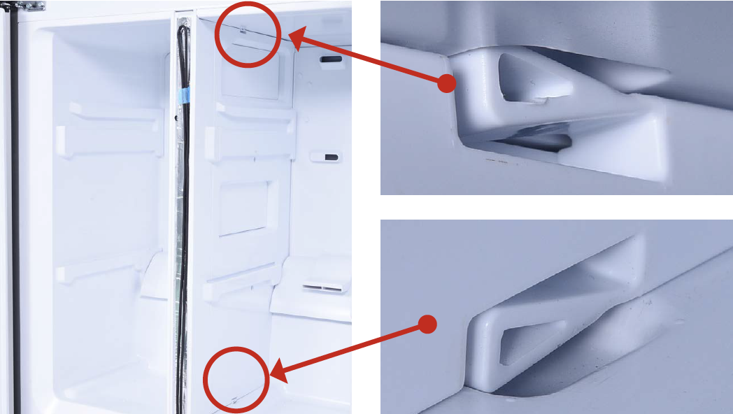
Tip 4
Ensure that latches are properly inserted into cavities.
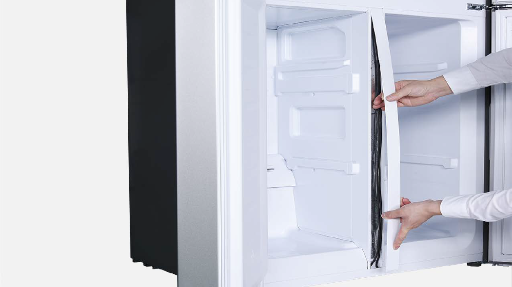
Tip 5
First, insert top of cover plate into the gap. Then, bend plate to insert the bottom. Lastly, snap middle into place.

GO BACK TO COMPONENT LIST