

CHECK AND TEST 1
Step 1
Unscrew cover of mainboard with a cross-head screwdriver.

Step 2
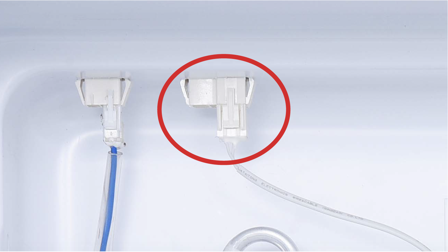
In PCB area, check if terminal is pushed into final position.
IF NOT, PUSH IT INTO FINAL POSITION.

Step 3
In PCB, check to see if terminal is full of foam.

IF SO, USE TWEEZERS TO REMOVE FOAM.

Step 4
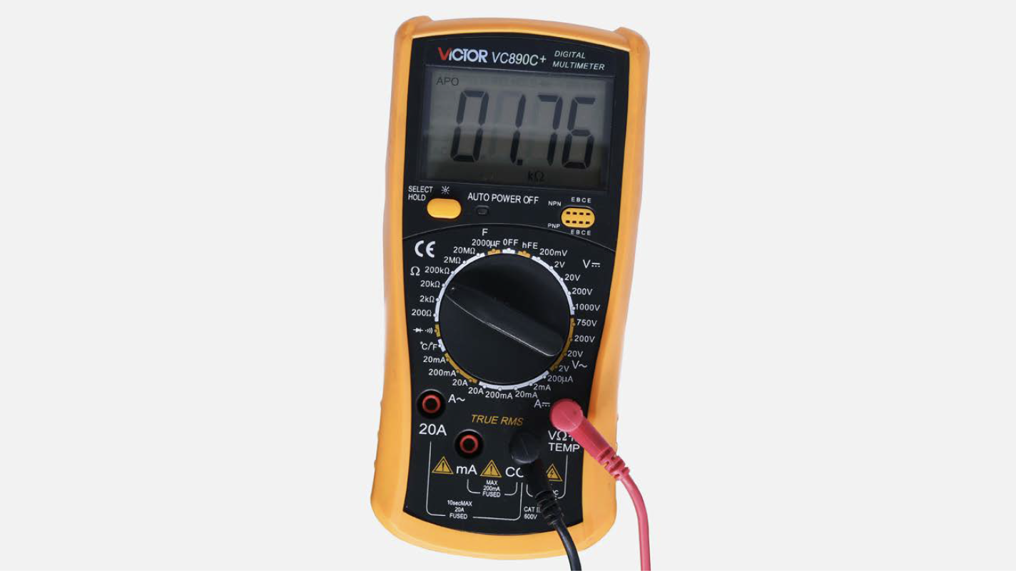
In PCB area, use multimeter to measure resistance value.

Step 5
Take note of the test result

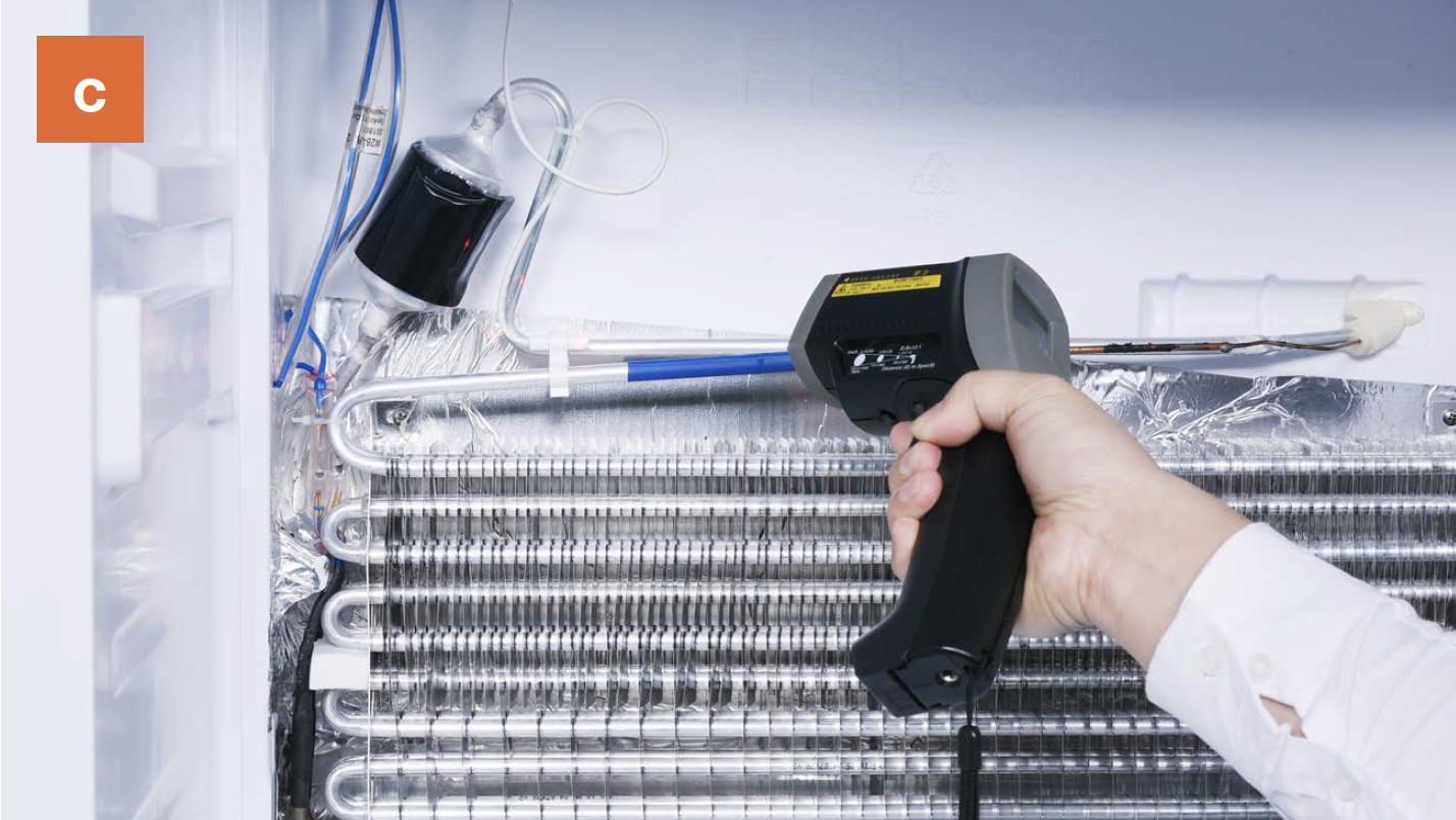
Step 6
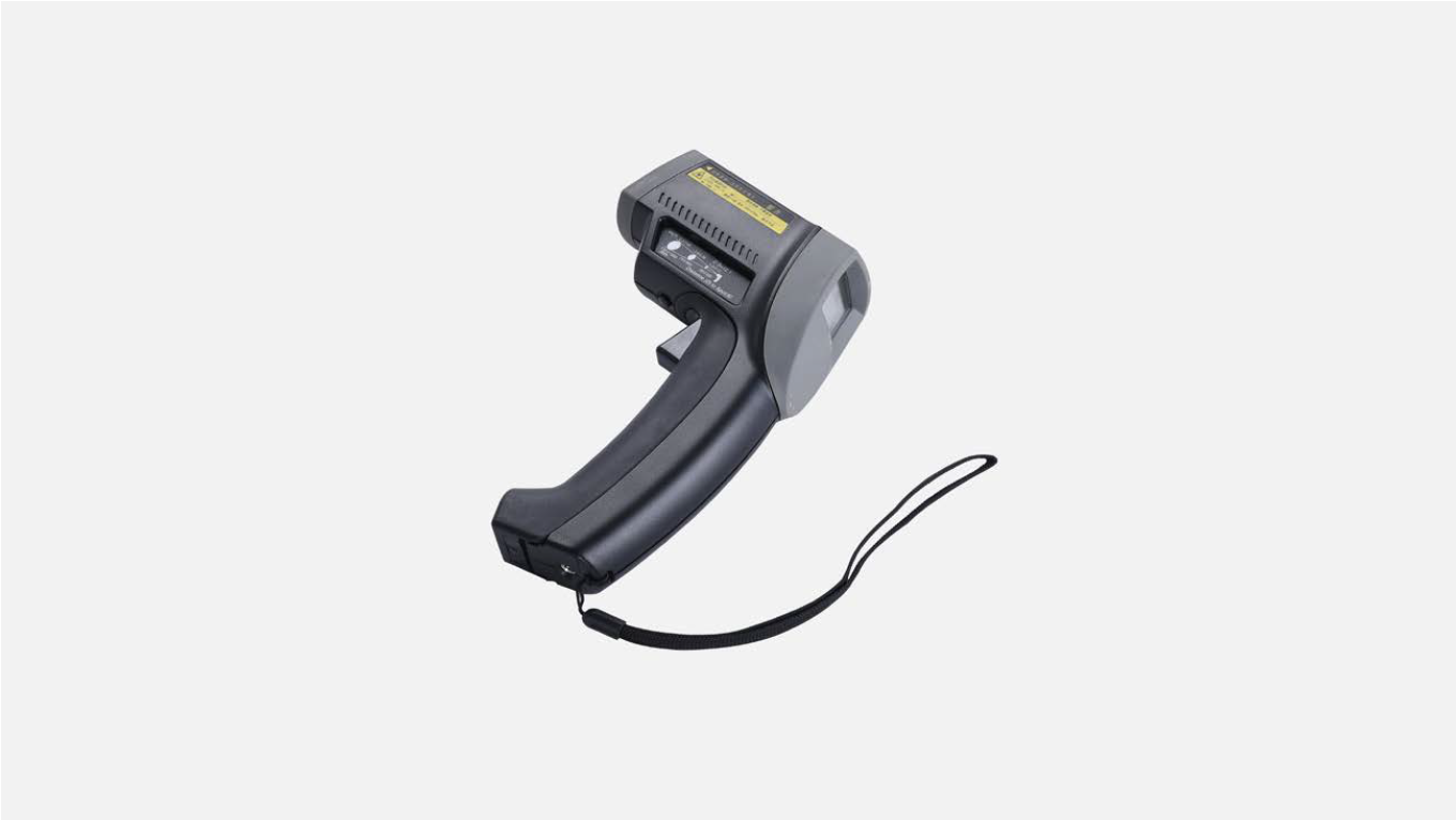
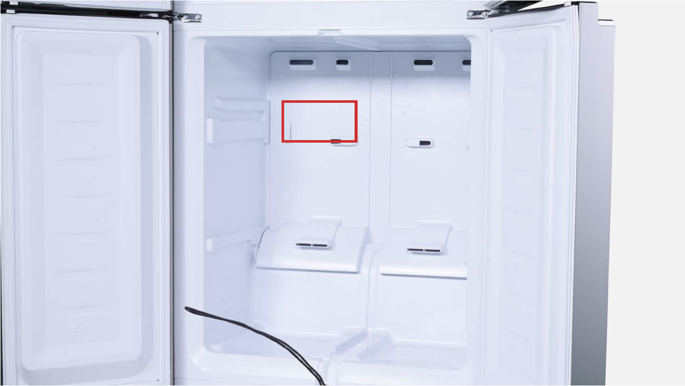
Use infrared detector to measure the temperature of freezer air duct (see red square in picture) for reference temperature for defrost temp. sensor.
Note
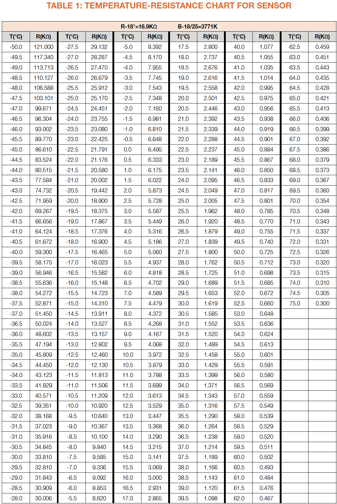
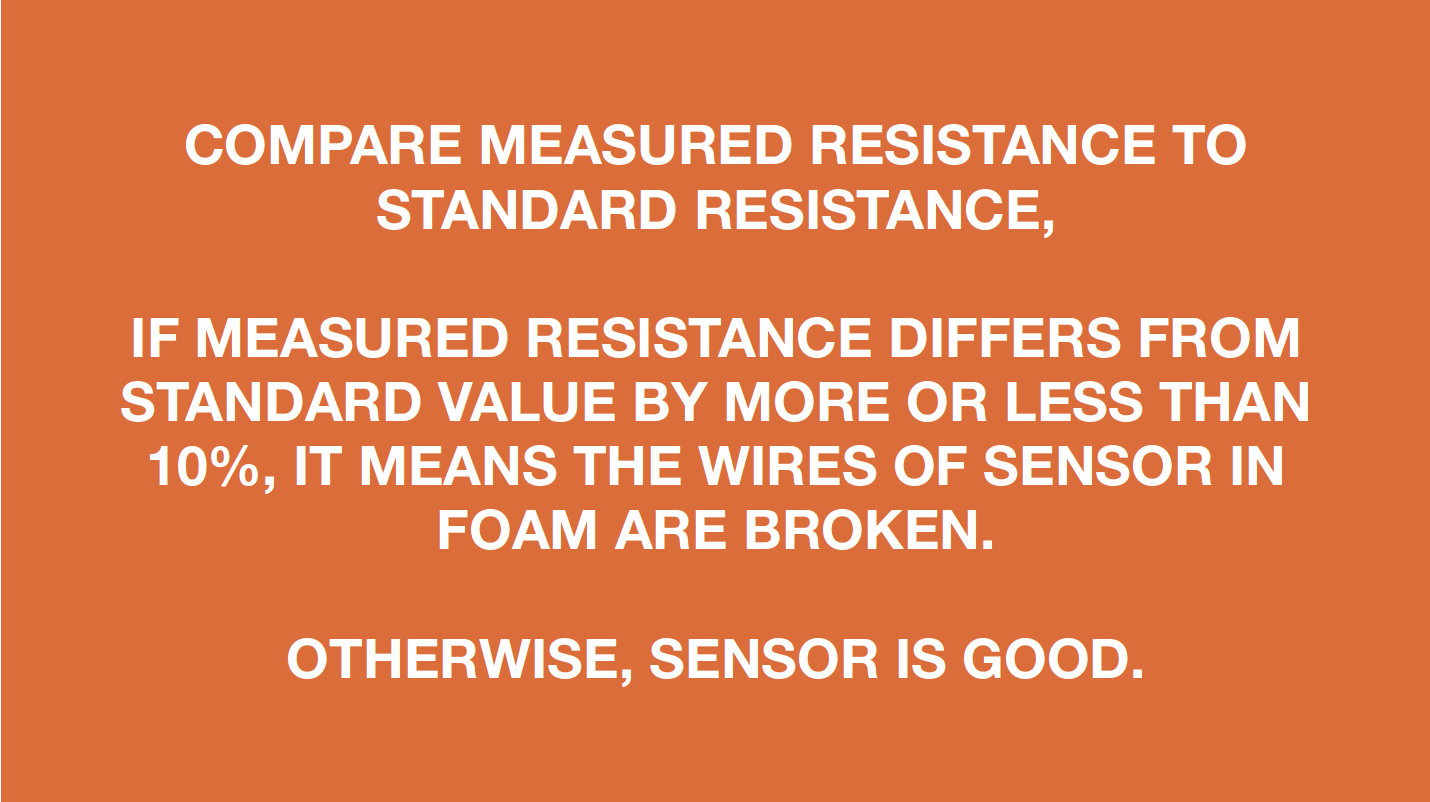
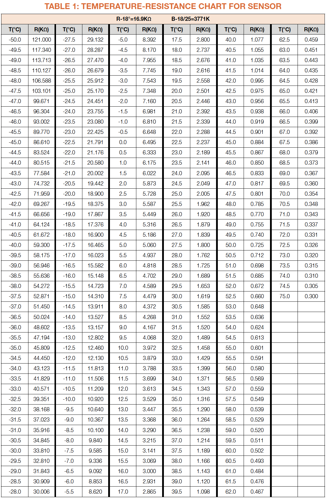
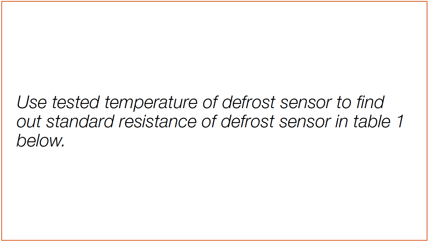
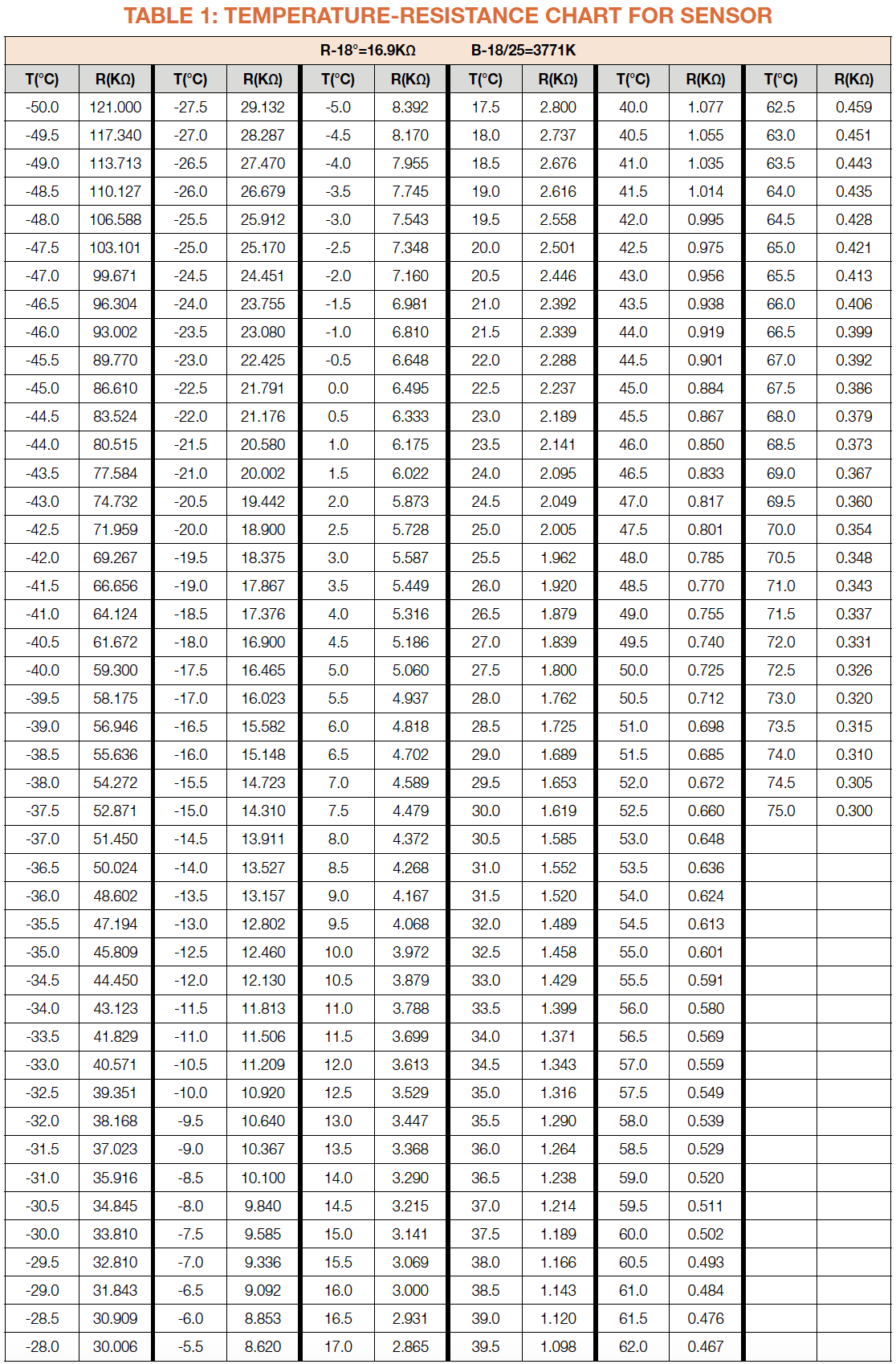
Use tested reference temperature to find out standard resistance value in table 1 below.
DIAGNOSIS 1


PROCEDURE 1
Step 1
Remove all the drawers.

Step 2
Remove all shelves.

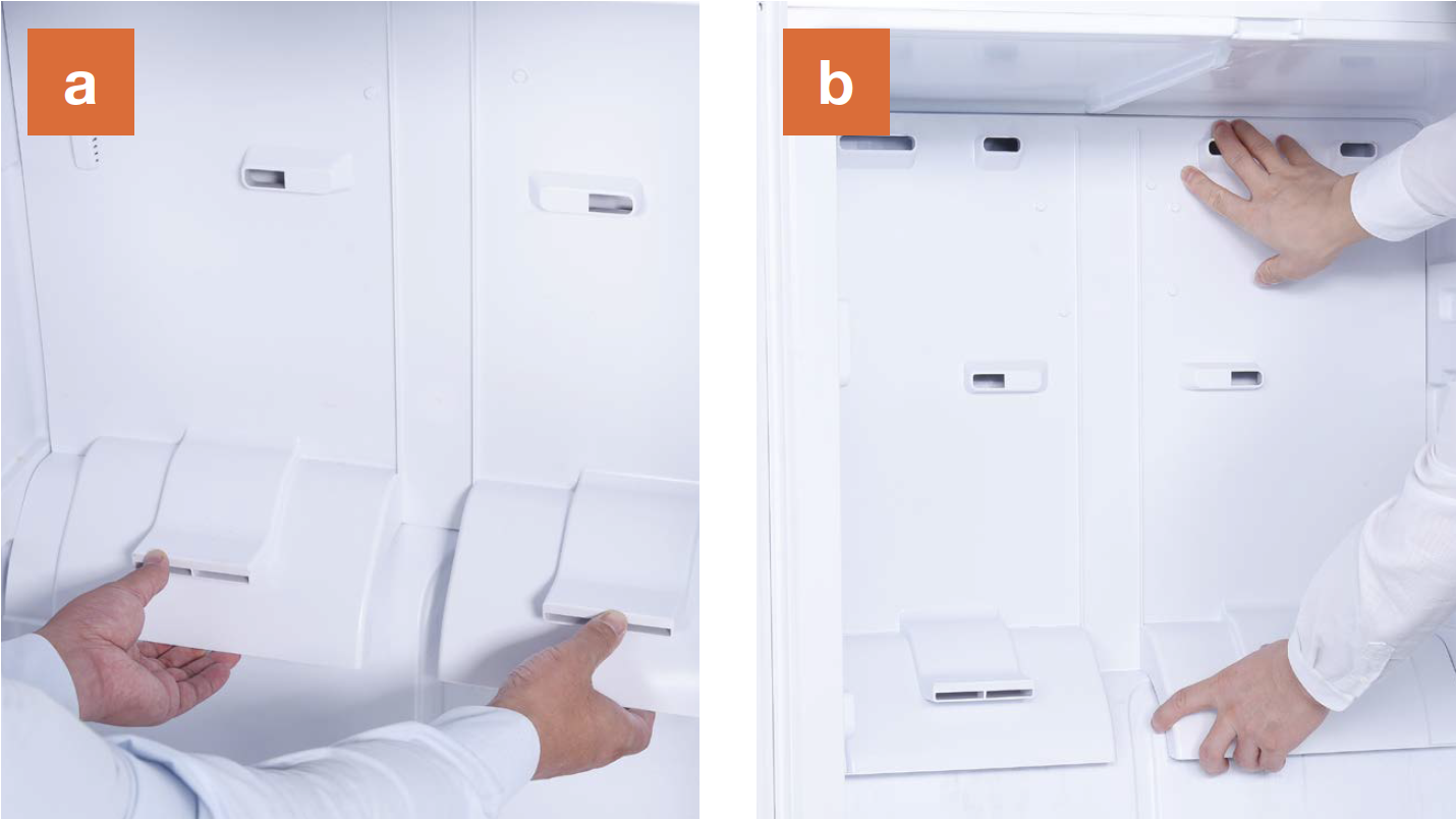
Step 3
Remove the vertical
partition plate:
a. Insert 2mm slotted
screwdriver into
the gap;
b. Lever up the cover
plate from bottom;
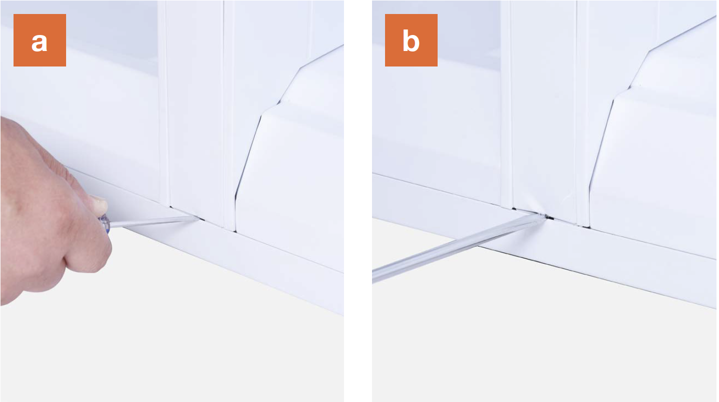
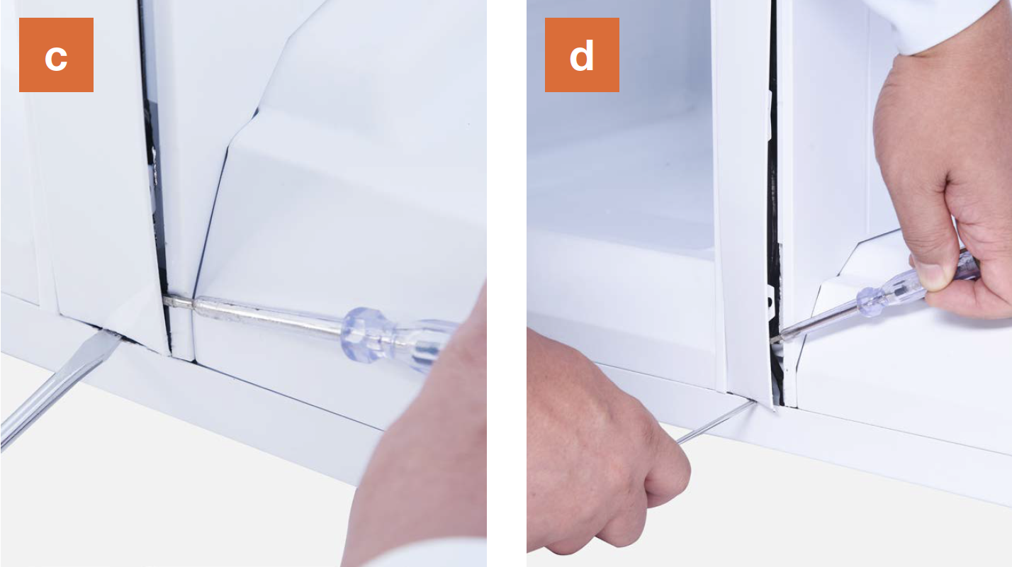
c. Insert 2mm slotted
screwdriver into the
side gap;
d. Lever up the cover
plate from bottom;
e. Pull the bottom end of
cover out;
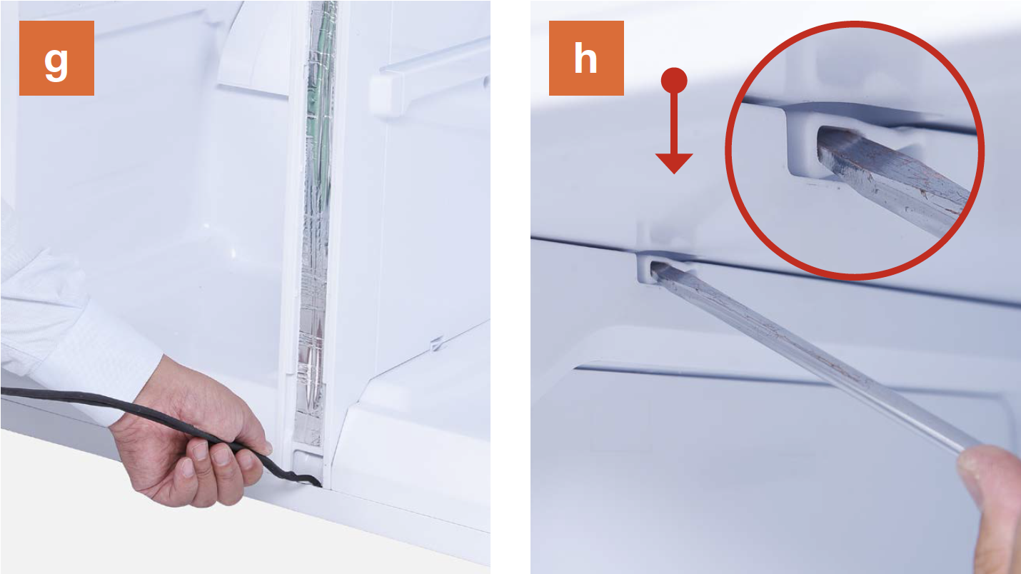
f. Pull the top of the
cover out;

g. Take pipes out and
place in horizontal
position;
h. Push latch down and
lift top out of cavity;
i. Push latch up and
pull bottom out of the
cavity;
j. Pull partition outward
and remove partition.
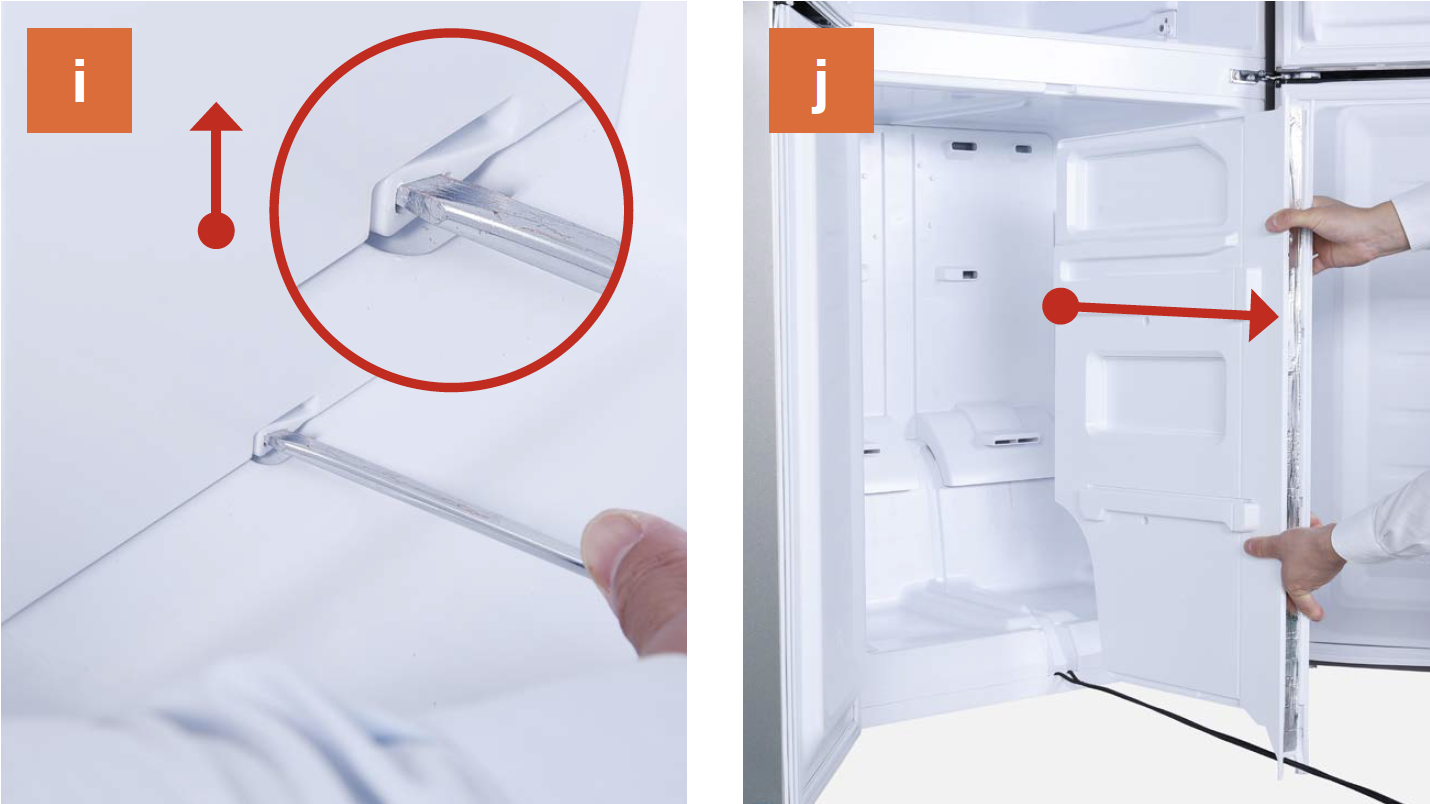
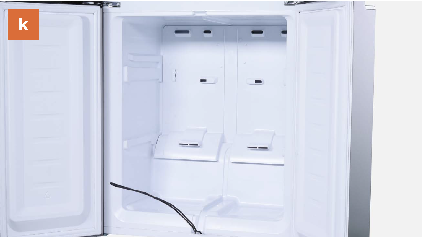
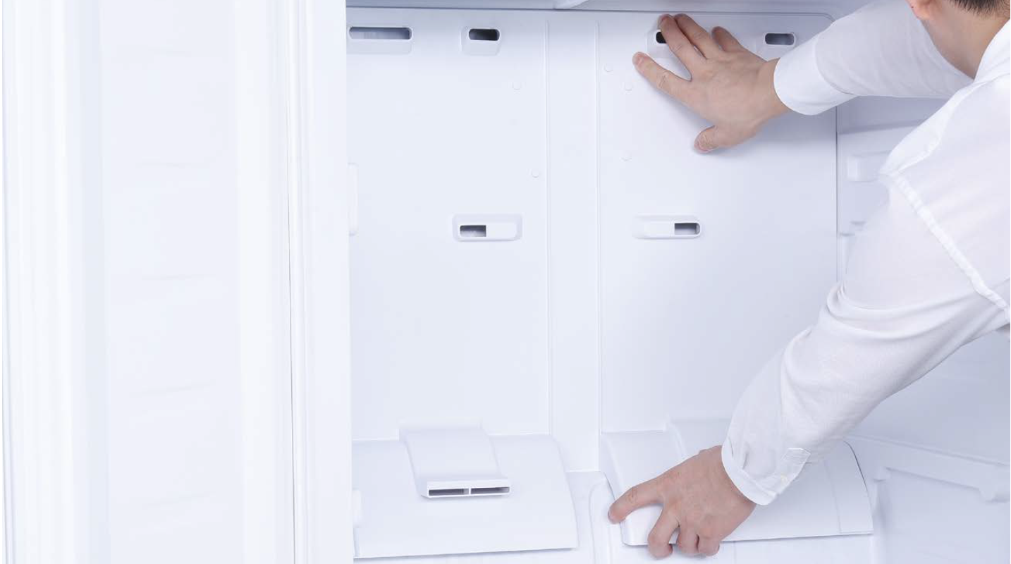
k. Internal view after partition has been removed.
Step 4
Dismantle the air duct.
a. Hold the bottom of
air duct;
b. Pull air duct out from
below;
c. Disconnect the terminal for fan motor;

d. Disconnect the terminal of freezer temp. sensor;
e. Remove air duct.

CHECK AND TEST 2
Step 1
Use a multimeter to measure the resistance value of defrost temp. sensor from terminal located in freezer.

a. Insert the detectors
into terminal and
make sure connection
is good;
b. Read the value;
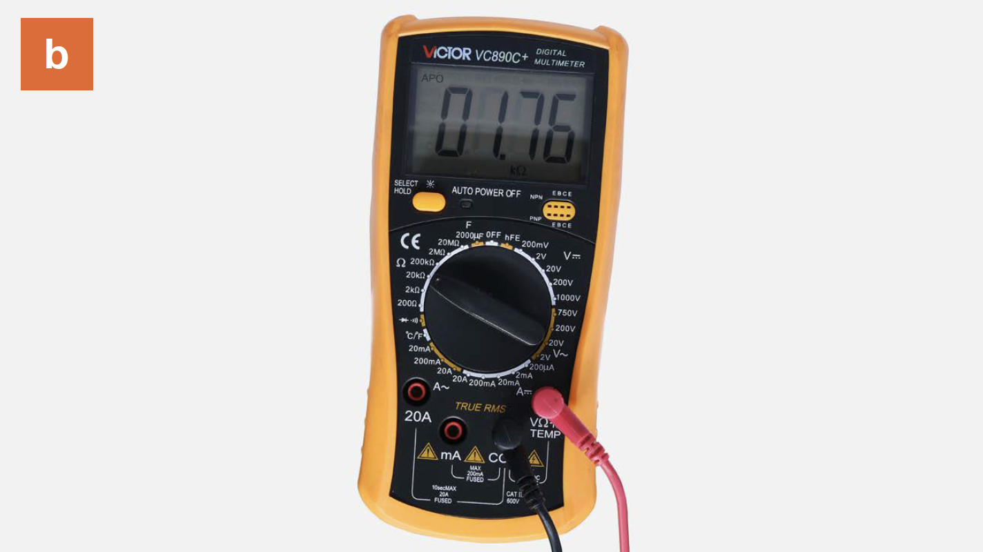
Step 2
Measure the temperature of defrost temp. sensor.
Note
DIAGNOSIS 2
PROCEDURE 2
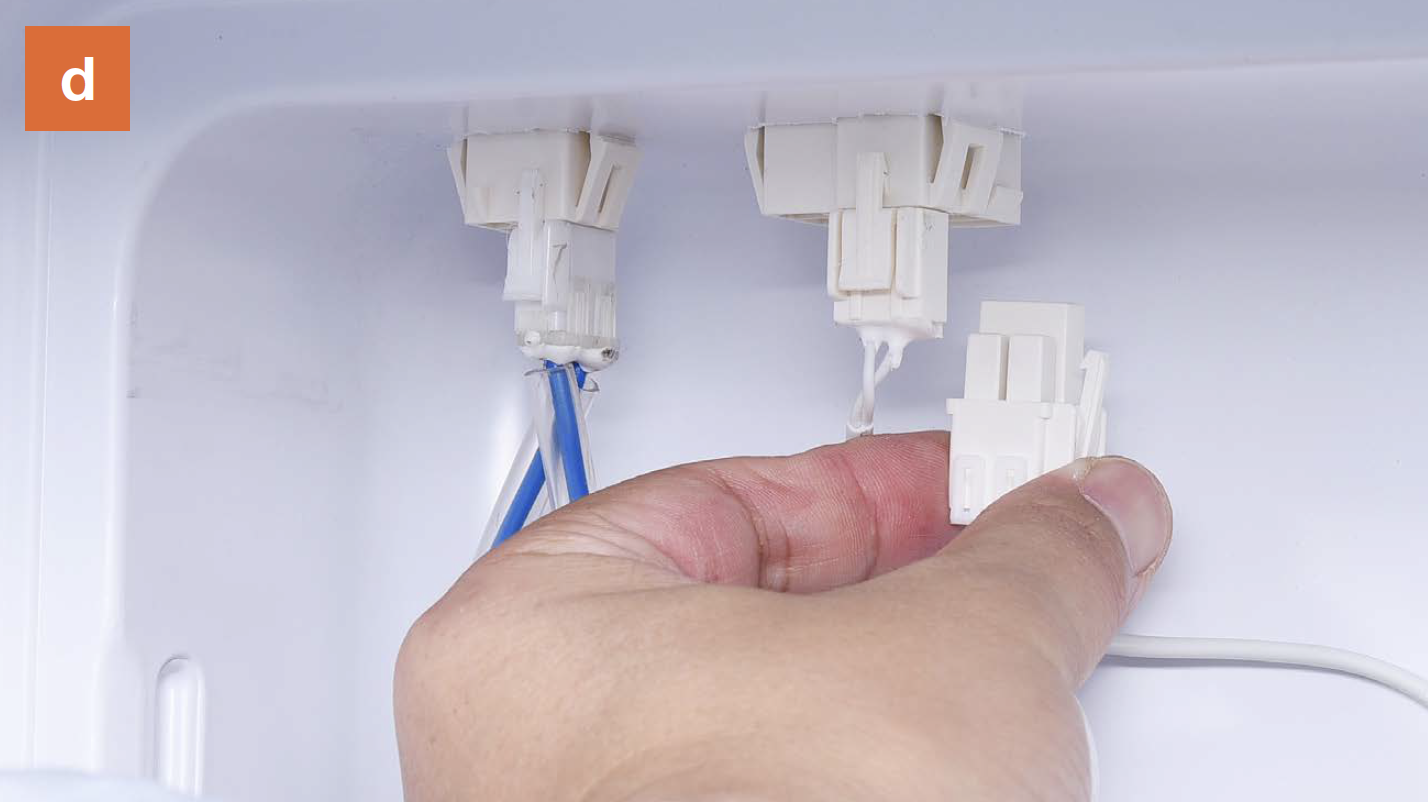
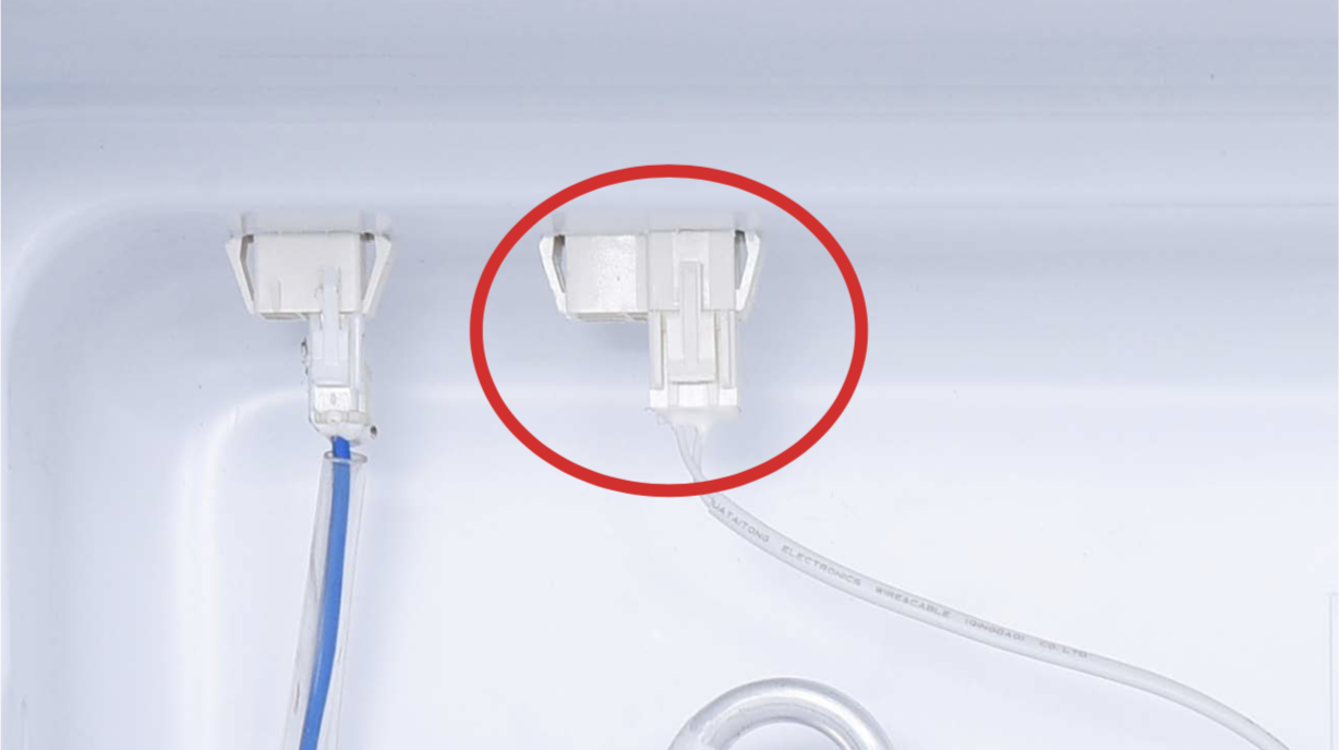
Step 1
Disconnect the terminal.
Step 2
Cut off plastic tie.
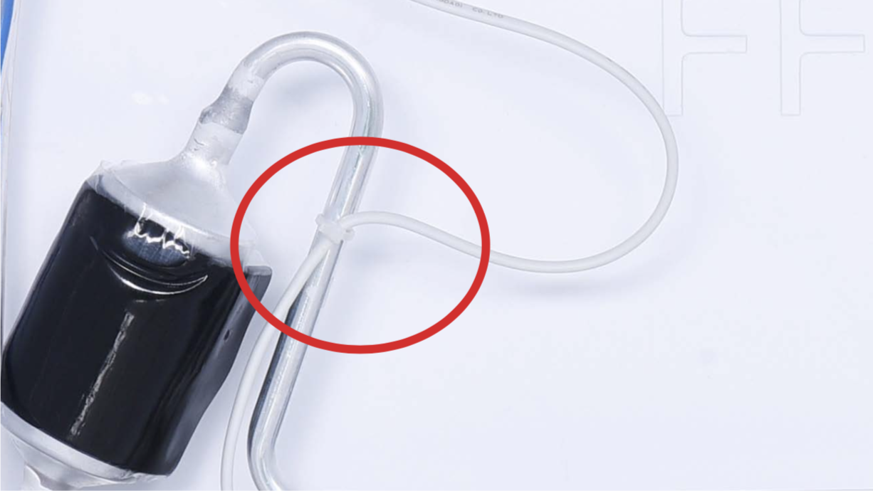
Step 3
Take sensor out of the
plastic buckle.
REVERSE STEPS
ABOVE TO INSTALL
DEFROST SENSOR.

CHECK AND TEST 3
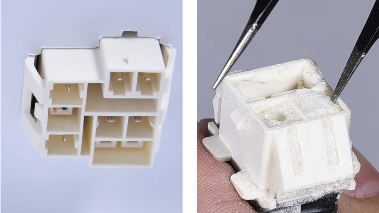
Step 1
Check to see if the
terminal is full of foam.
IF SO, USE TWEEZERS
TO CRUSH AND
REMOVE FOAM.
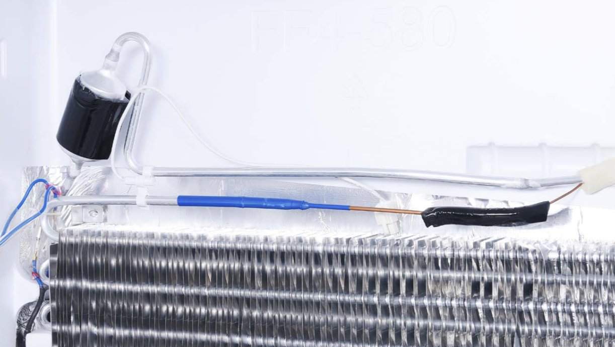
Step 2
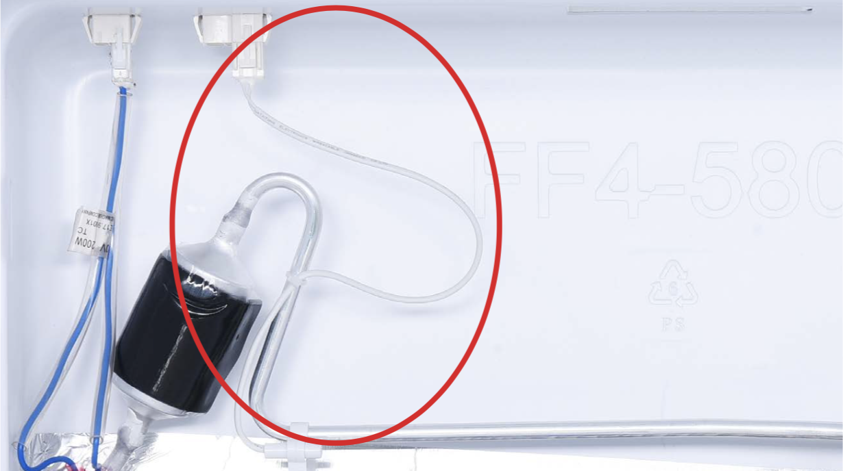
Make sure sensor is
properly located by
comparing with photo
on right.
IF SENSOR IS NOT IN
SAME POSITION AS
PHOTO, FIX IT.
Step 3
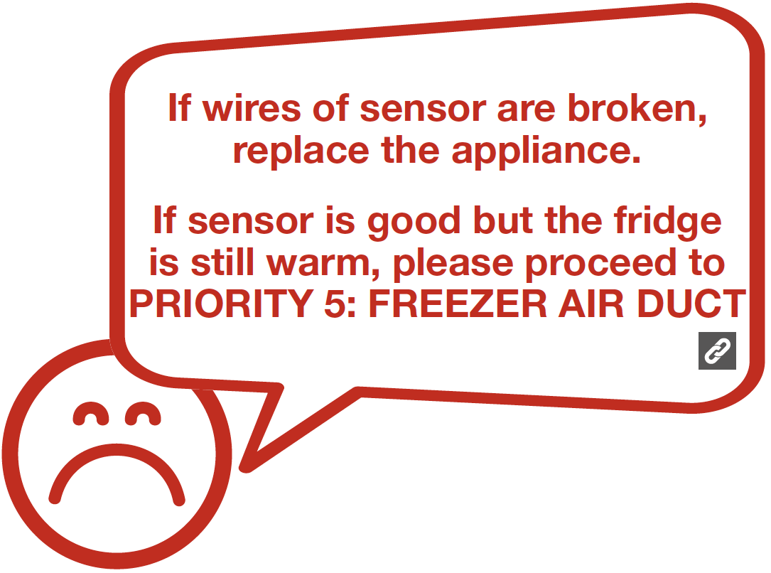
Check to see if sensor wires have been cut off; if so, follow procedures below to rework.
DIAGNOSIS 3
PROCEDURE 3

Step 1
Cut off the wire.

Step 2
Peel off the sleeves
Step 3
Check for proper wire order, then connect them.

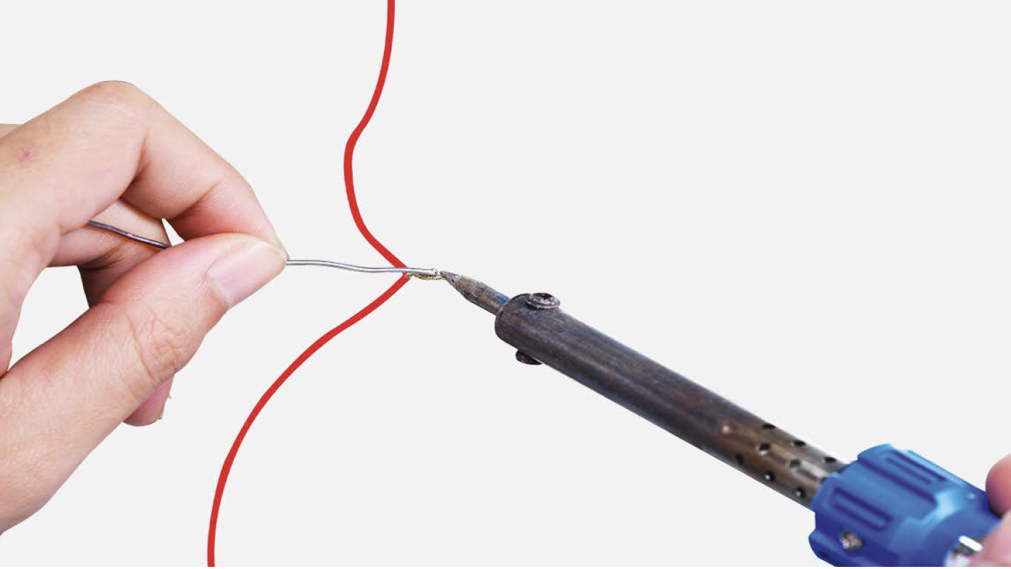
Step 4
Tin soldering.
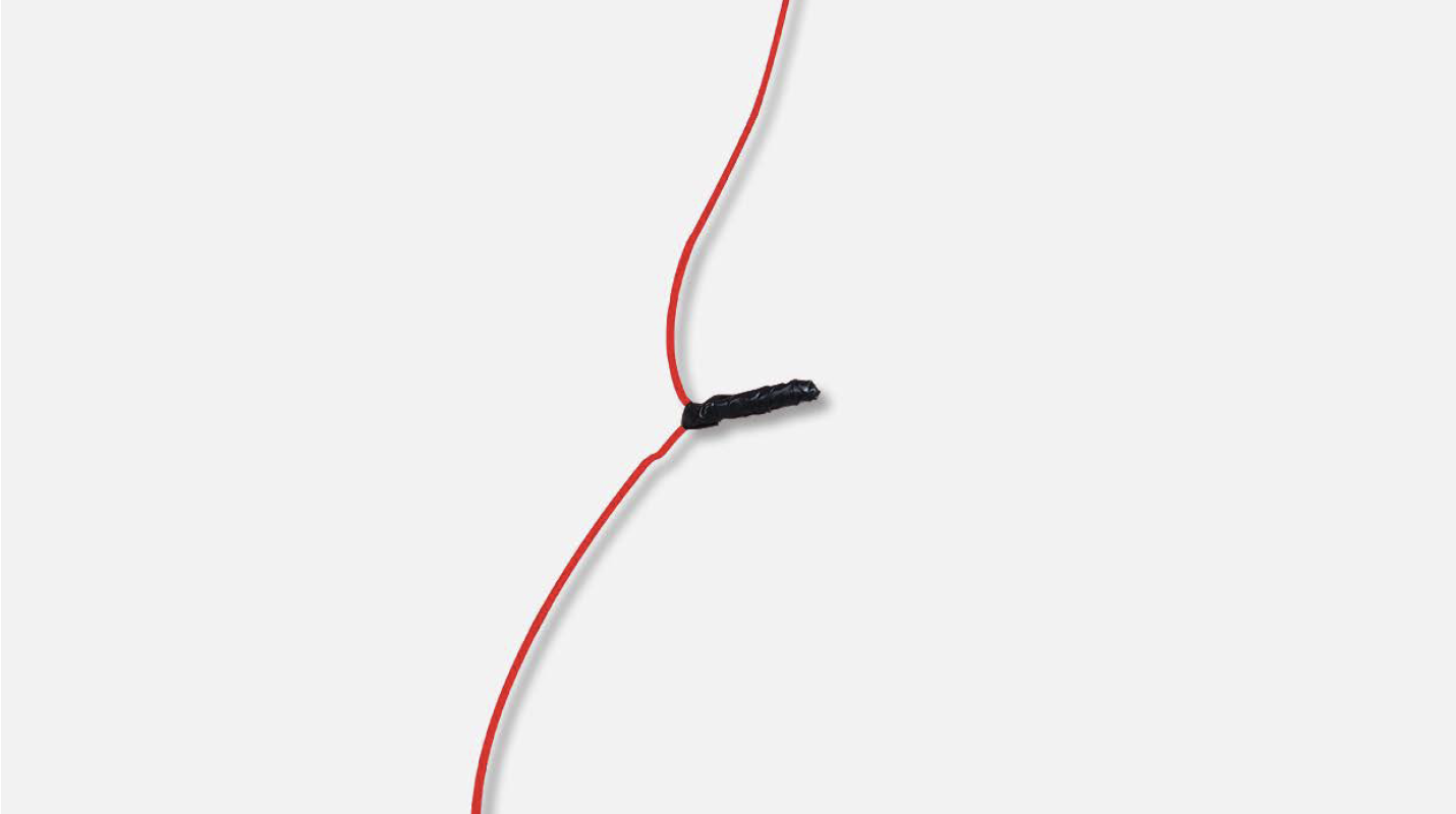
Step 5
Cover point of connection with electrical tape.
CHECK AND TEST 4
Step 1
After confirming the sensor and terminals are OK, or replace the sensor, reconnect the terminal.
Step 2
Use a multimeter to measure the resistance value of defrost temp. sensor from terminal located in mainboard area.
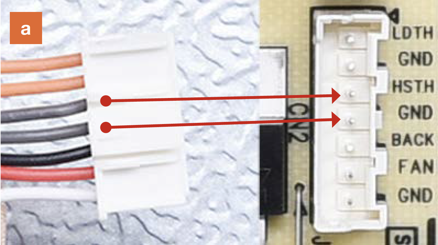
a. Insert the detectors
into terminal and
make sure connection
is good;
b. Read the value;
Step 3
Measure the temperature of defrost temp. sensor.

Note
DIAGNOSIS 4
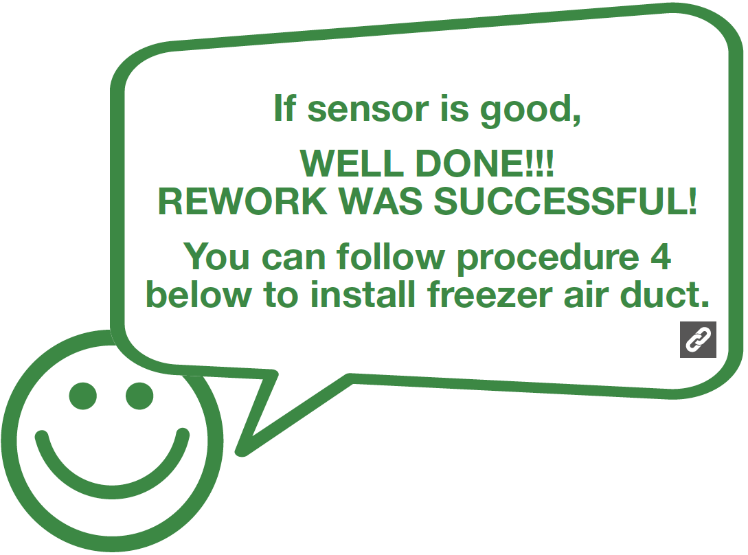

PROCEDURE 4
Tip 1
When installing the air duct, make sure to move wires out of the way to prevent crushing by air duct.

Tip 2
After pushing air duct back into position, you should hear a clicking sound. If not, repeat again.
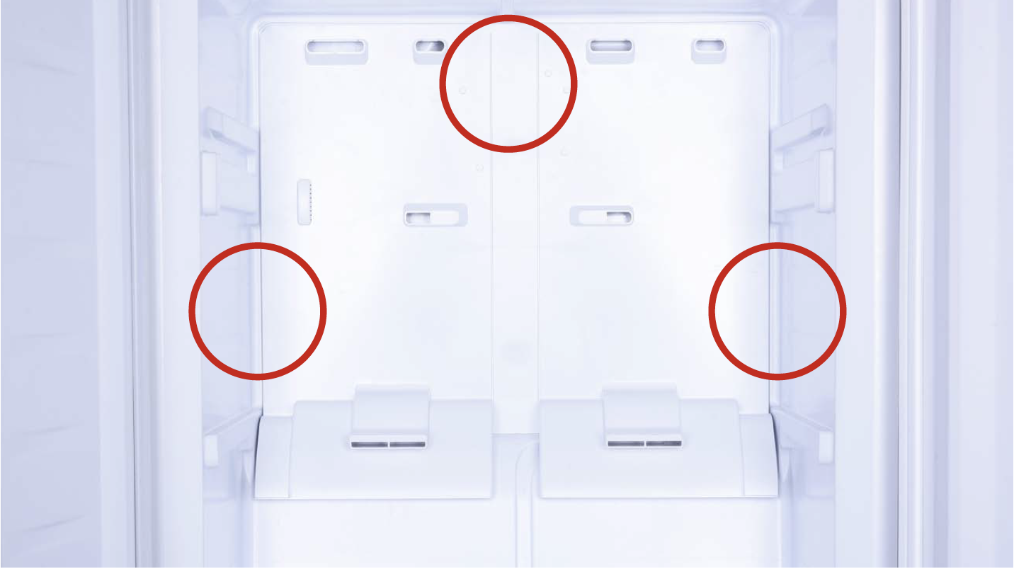
Tip 3
Check to see whether there is a wide gap between air duct and cabinet. If so, reinstall air duct again.
Tip 4
Check to ensure latches are properly inserted into cavities.

Tip 5
First, insert top of cover plate into the gap, then bend plate to insert the bottom. Lastly, snap middle into slot.


GO BACK TO COMPONENT LIST