CHECK AND TEST 1
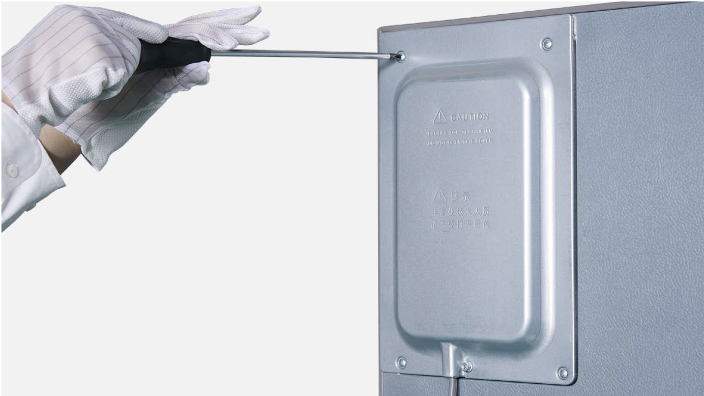
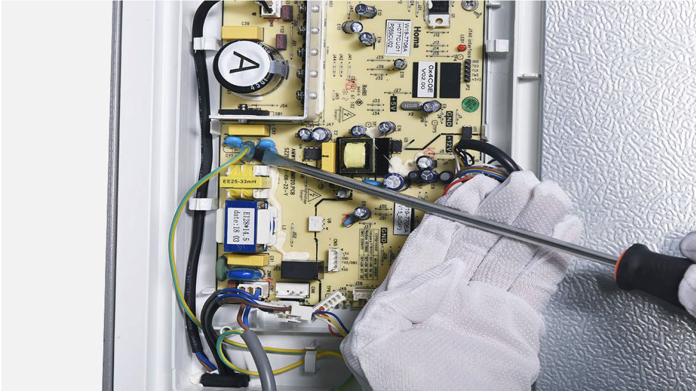
Step 1
Unscrew cover of mainboard with a cross- head screwdriver.

Step 2
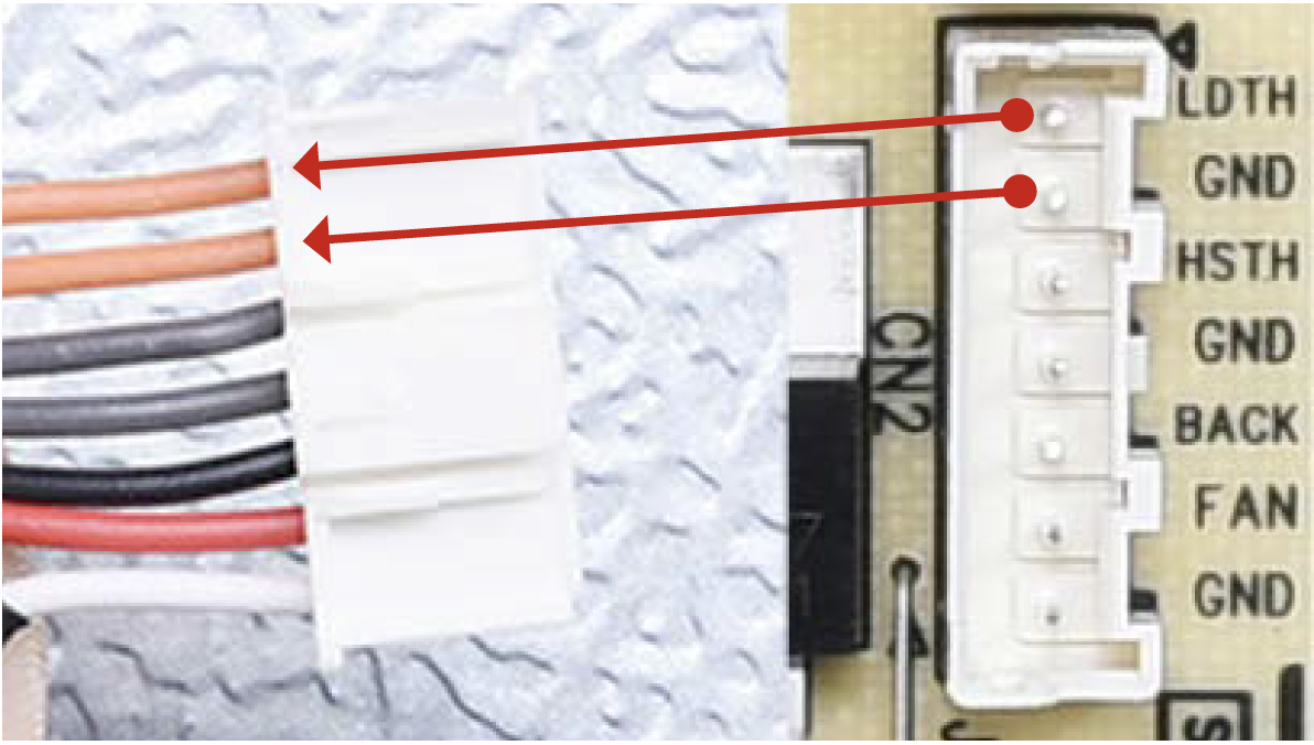
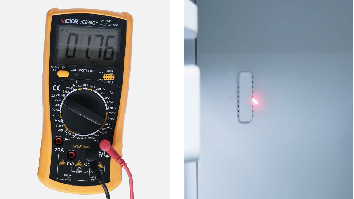
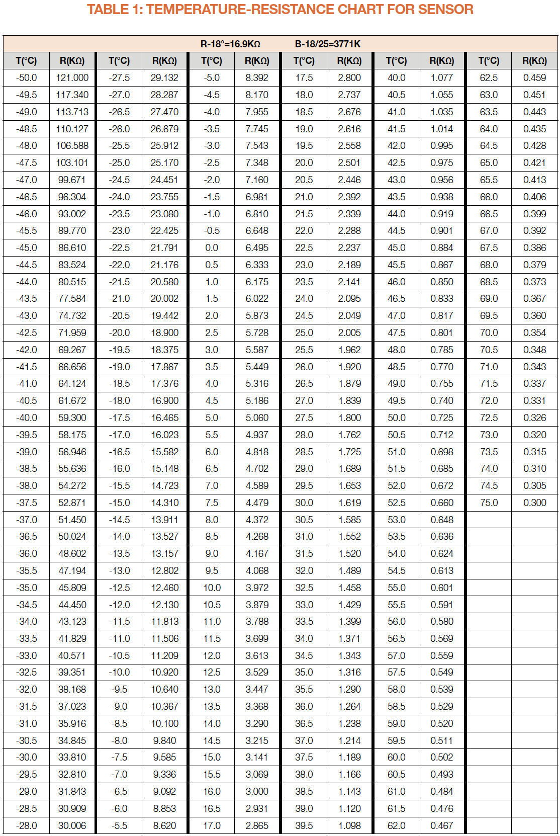
Measure resistance of sensor from terminal in PCB area.
Step 3
Take note of resistance value.
Step 4
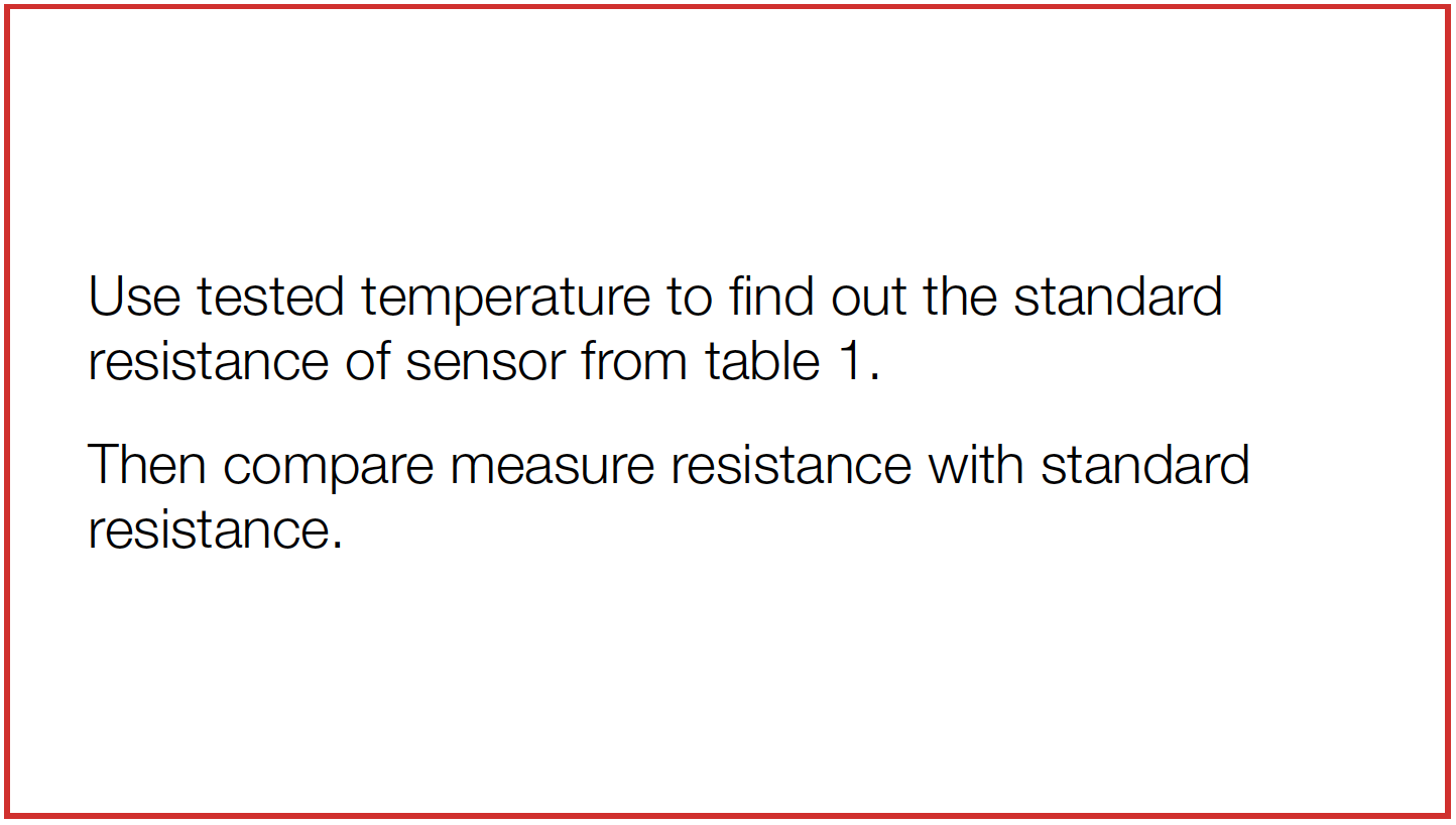
Measure the temperature of sensor.
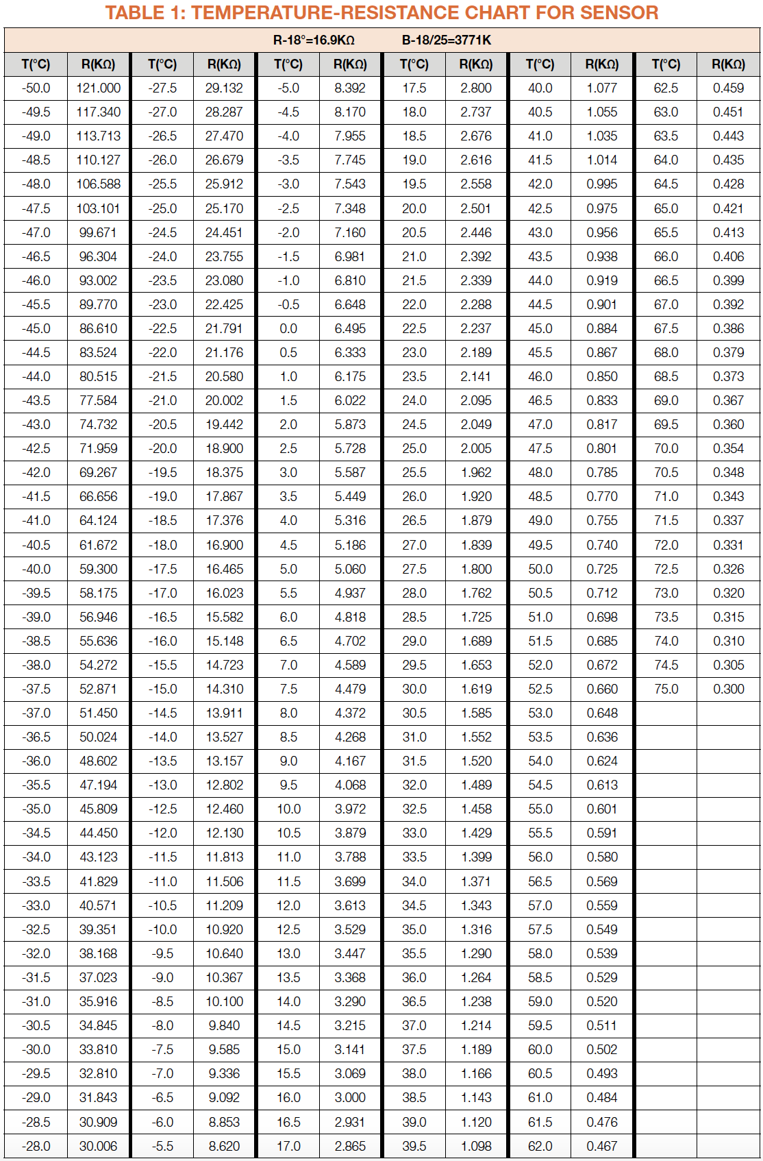
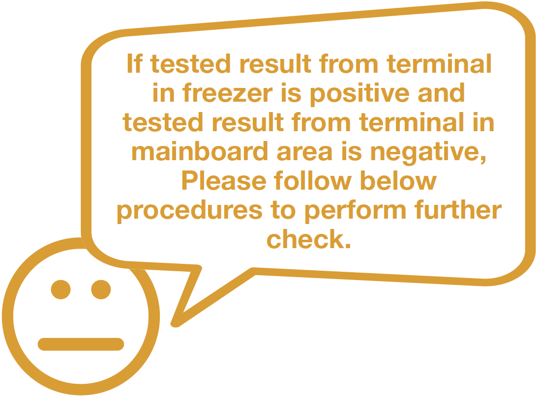
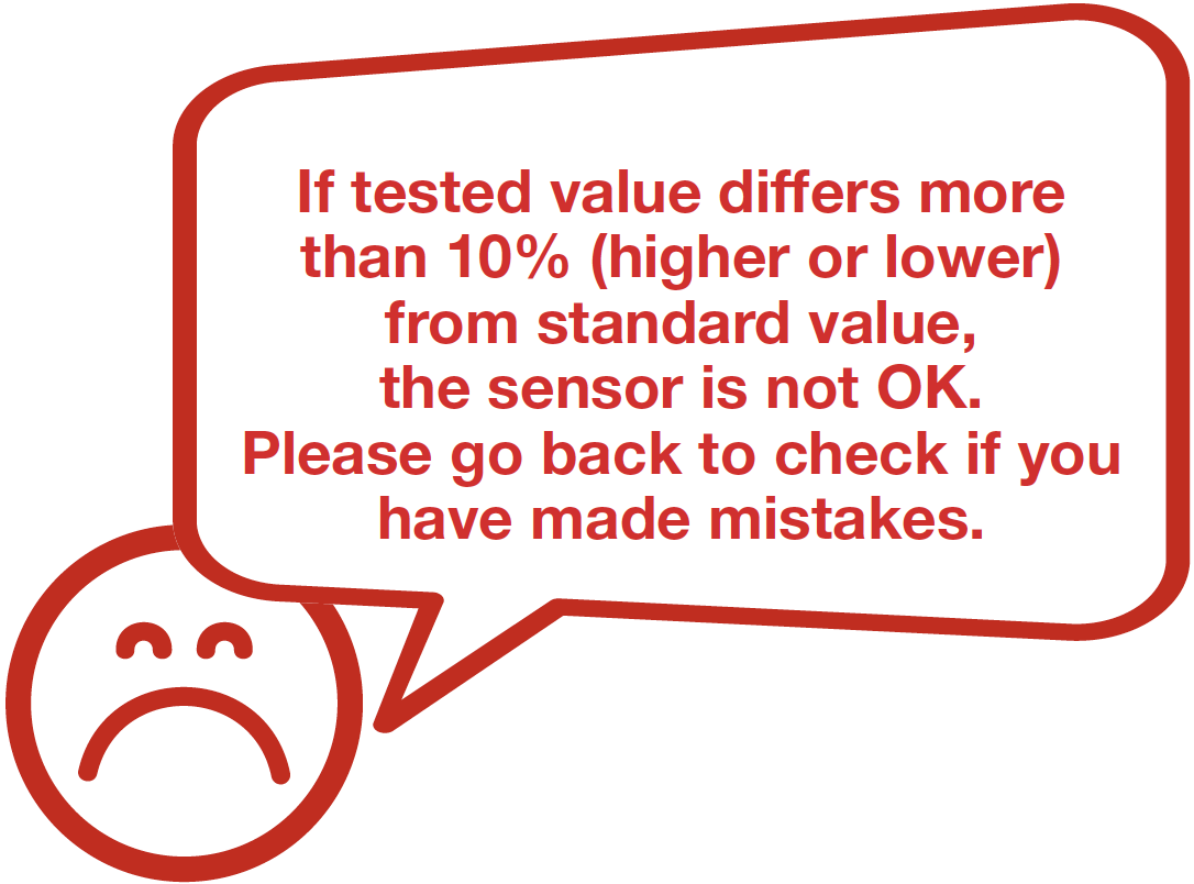
NOTE


PROCEDURE 1
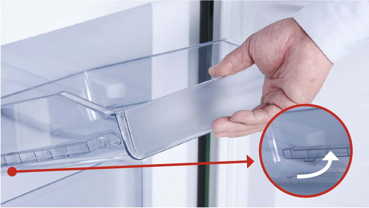
Step 1
Remove all the drawers.
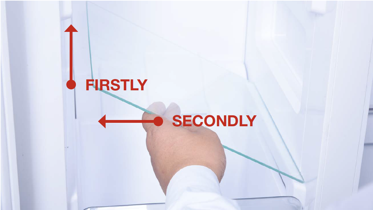
Step 2
Remove all shelves.
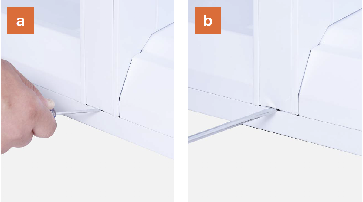
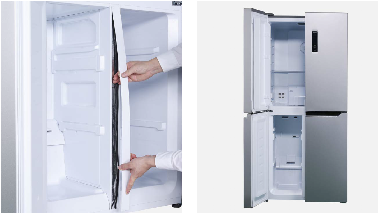
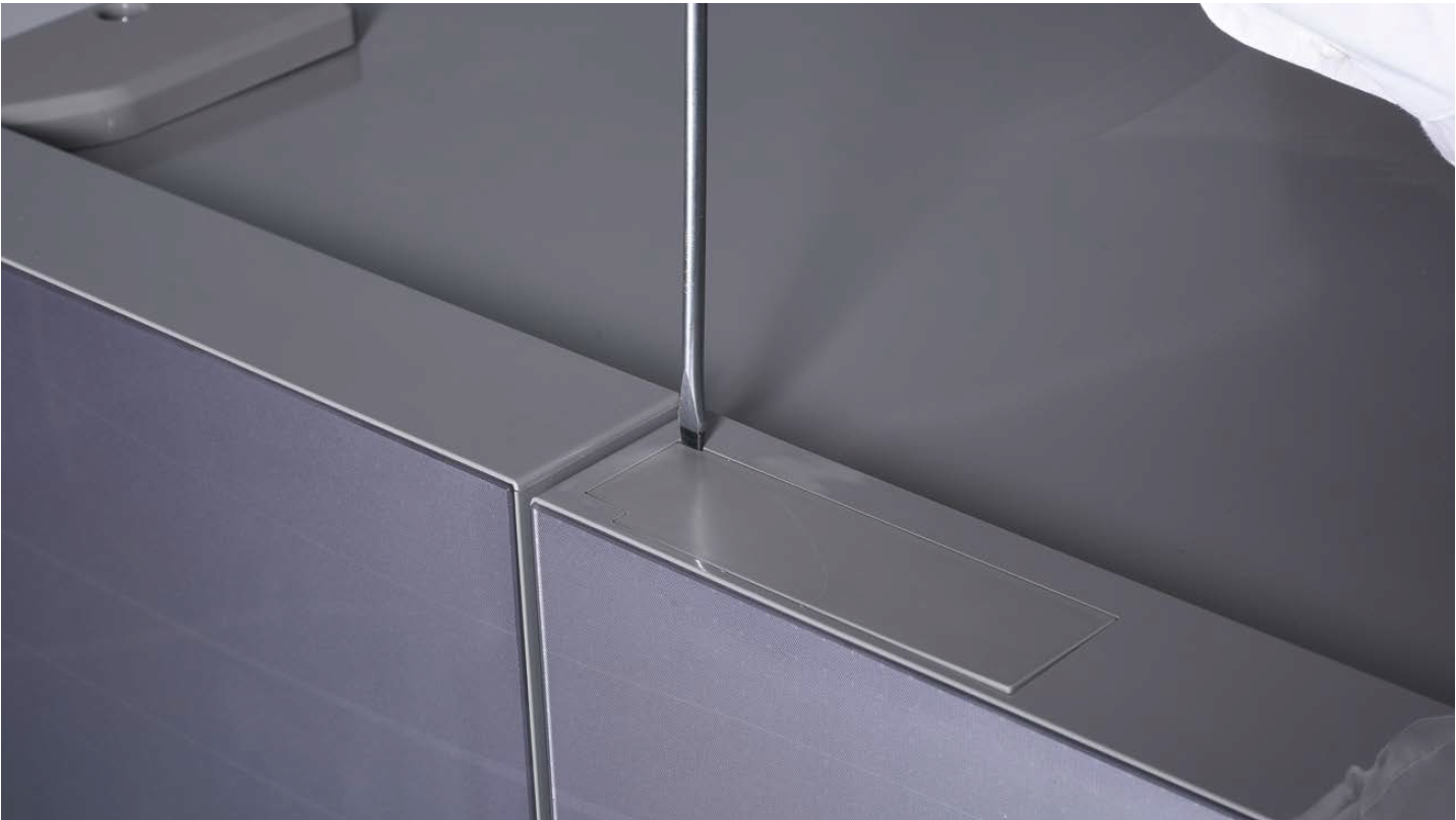
Step 3
Remove the vertical
partition plate:
a. Insert 2mm slotted
screwdriver into
the gap;
b. Lever up the cover
plate from bottom;
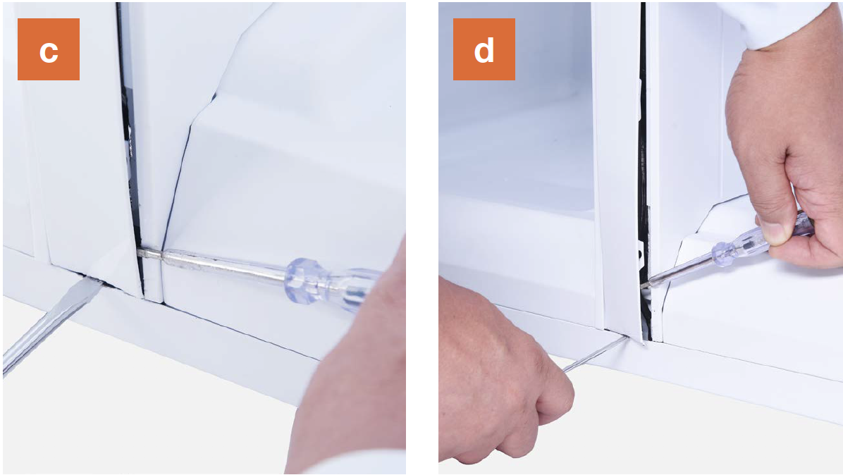
c. Insert 2mm slotted
screwdriver into the
side gap;
d. Lever up the cover
plate from bottom;
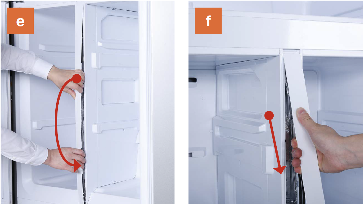
e. Pull the bottom end of
cover out;
f. Pull the top of the
cover out;
g. Take pipes out and
pull them into
horizontal position.
h. Push the latch down
and lift top out of the
cavity.

i. Push latch up and pull
bottom out of cavity;
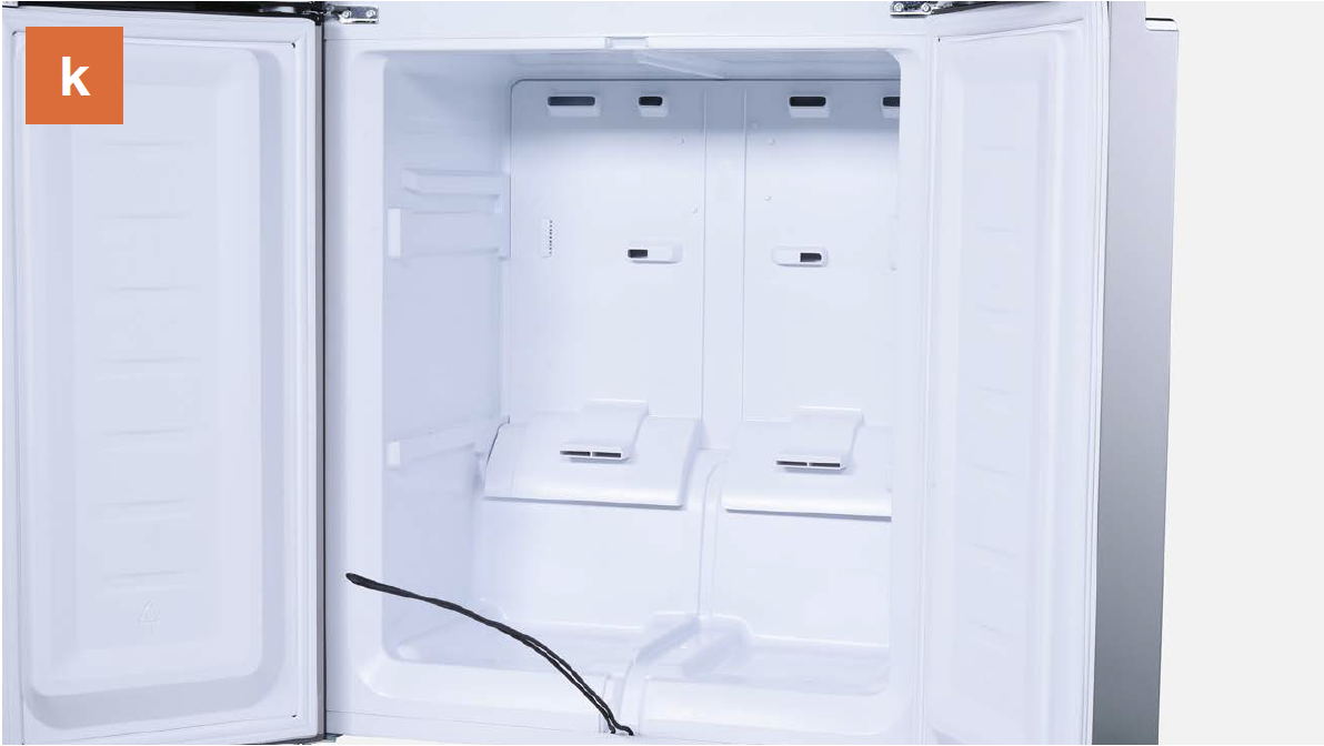
j. Pull the partition
outward and remove
the partition;

k. View of interior after partition has been removed.
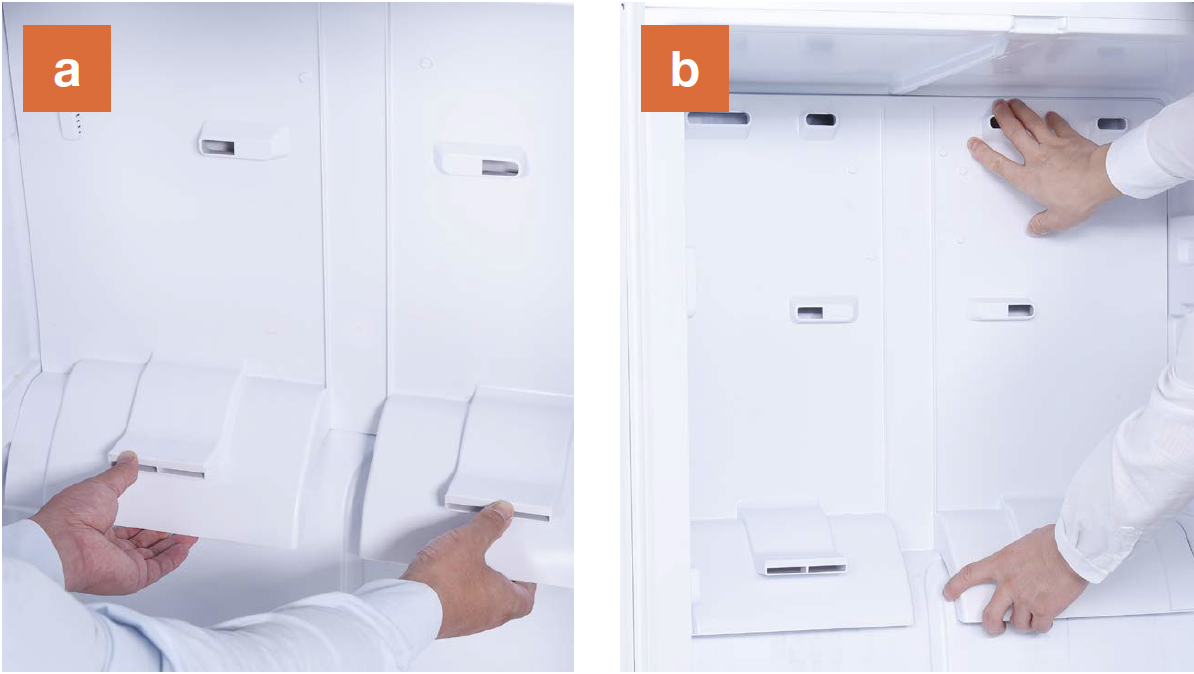
Step 4
Dismantle the air duct.
a. Hold the bottom of
air duct;
b. Pull air duct out from
below;
c. Disconnect the
terminal for fan motor;
d. Disconnect the
terminal of freezer temp. sensor;
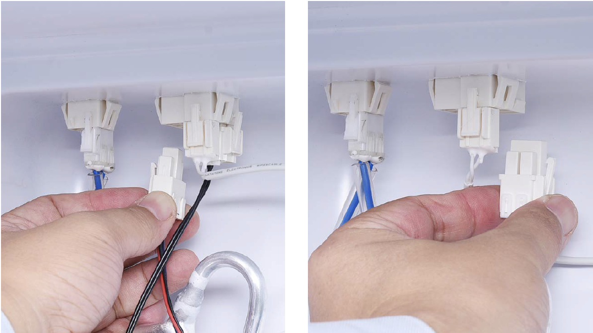
e. Move air duct away.

CHECK AND TEST 2
Step 1
Measure resistance of sensor from terminal in freezer.

Step 2
Take note of resistance value.
Step 3
Measure the temperature of sensor.

NOTE
DIAGNOSIS 2

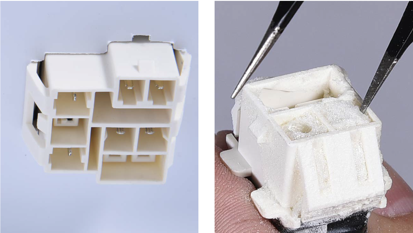
CHECK AND TEST 3
Step 1
Check to see if the
terminal is full of foam.
IF SO, USE TWEEZERS
TO CRUSH AND
REMOVE FOAM.
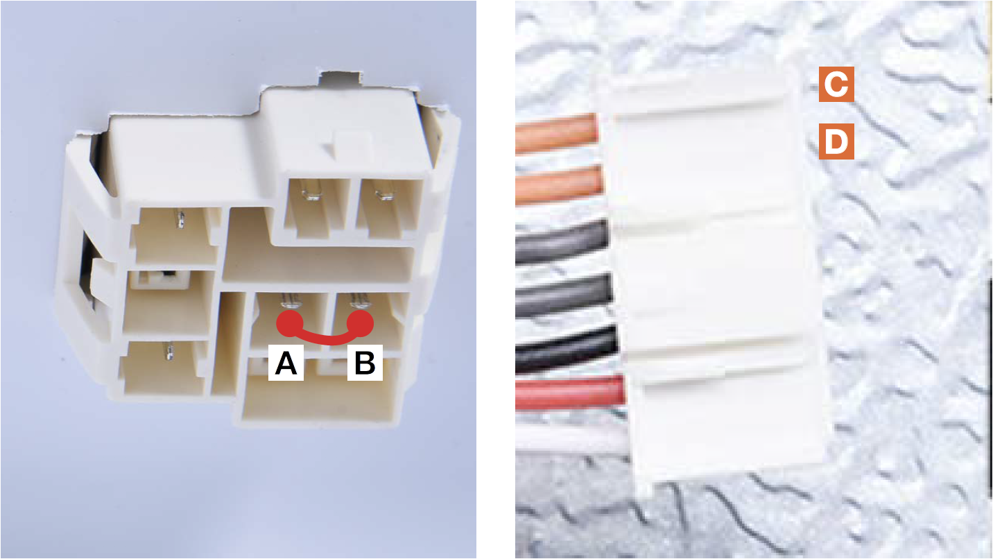
Step 1
Connect A to B with
metal wire.
Use multimeter to
measure the connection
from D and D.
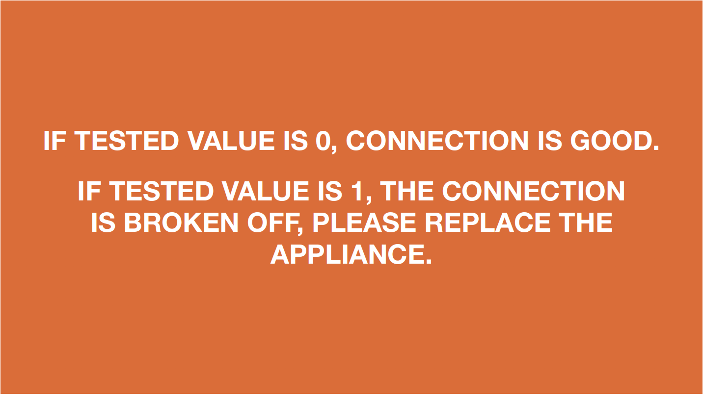
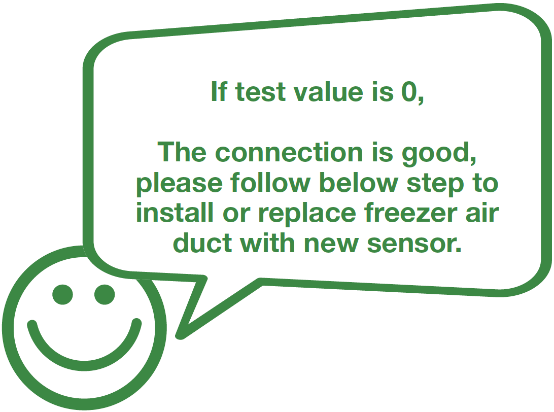
DIAGNOSIS 3
Step 1
Check to see if the
terminal is pushed into
final position.
If not, push it to final
position.

Note


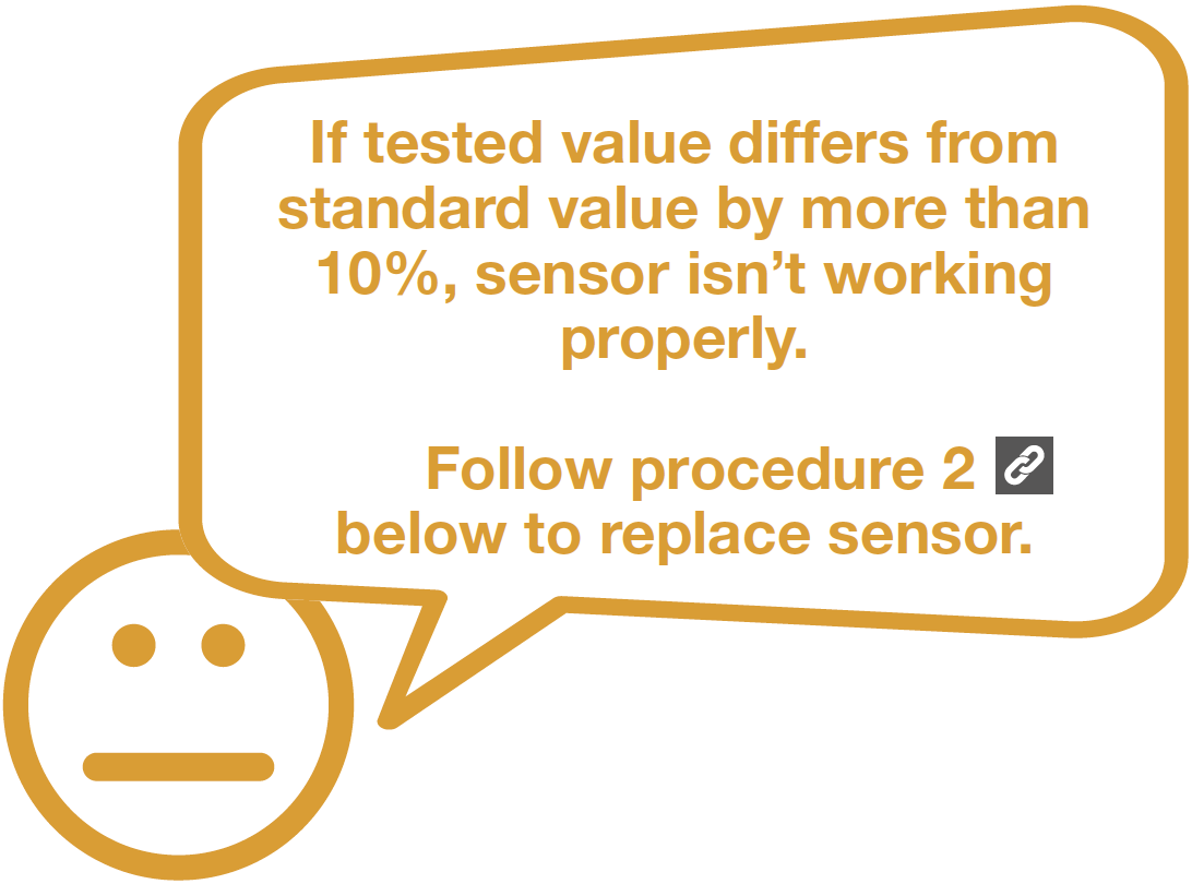
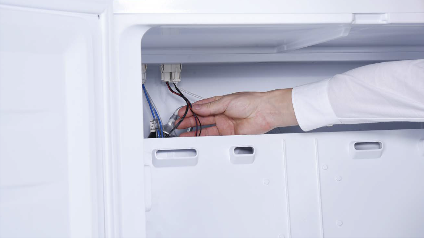
PROCEDURE 2
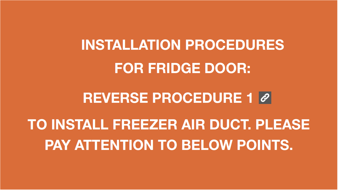
Tip 1
When remounting air duct, move wires out of the way to avoid crushing them with air duct.
Tip 2
After pushing air duct into place, you should hear a clicking sound. If not, repeat again.

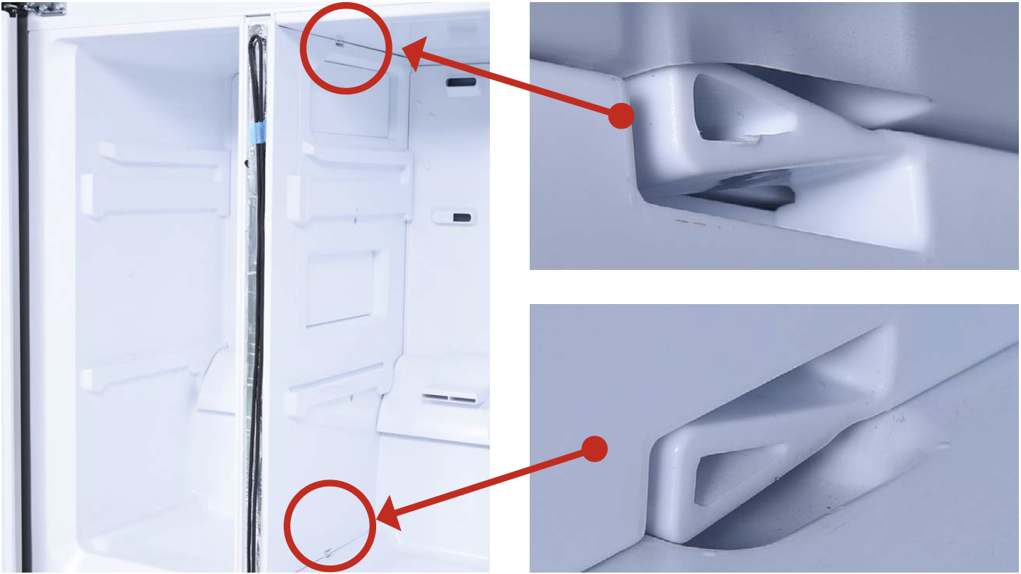
Tip 3
Check to see if there is
a wide gap between air
duct and cabinet.
IF SO, install air duct
again.

Tip 4
Check to make sure
the latches are inserted
properly into the cavities.
Tip 5
First, insert top of cover plate into gap, then bend plate to insert the bottom. Lastly, push the middle into the slit.
CHECK AND TEST 4
Step 1
Measure resistance of sensor from terminal in PCB area.

Step 2
Take note of resistance
value.
Step 3
Measure the temperature of sensor.

NOTE

DIAGNOSIS 4


PROCEDURE 3

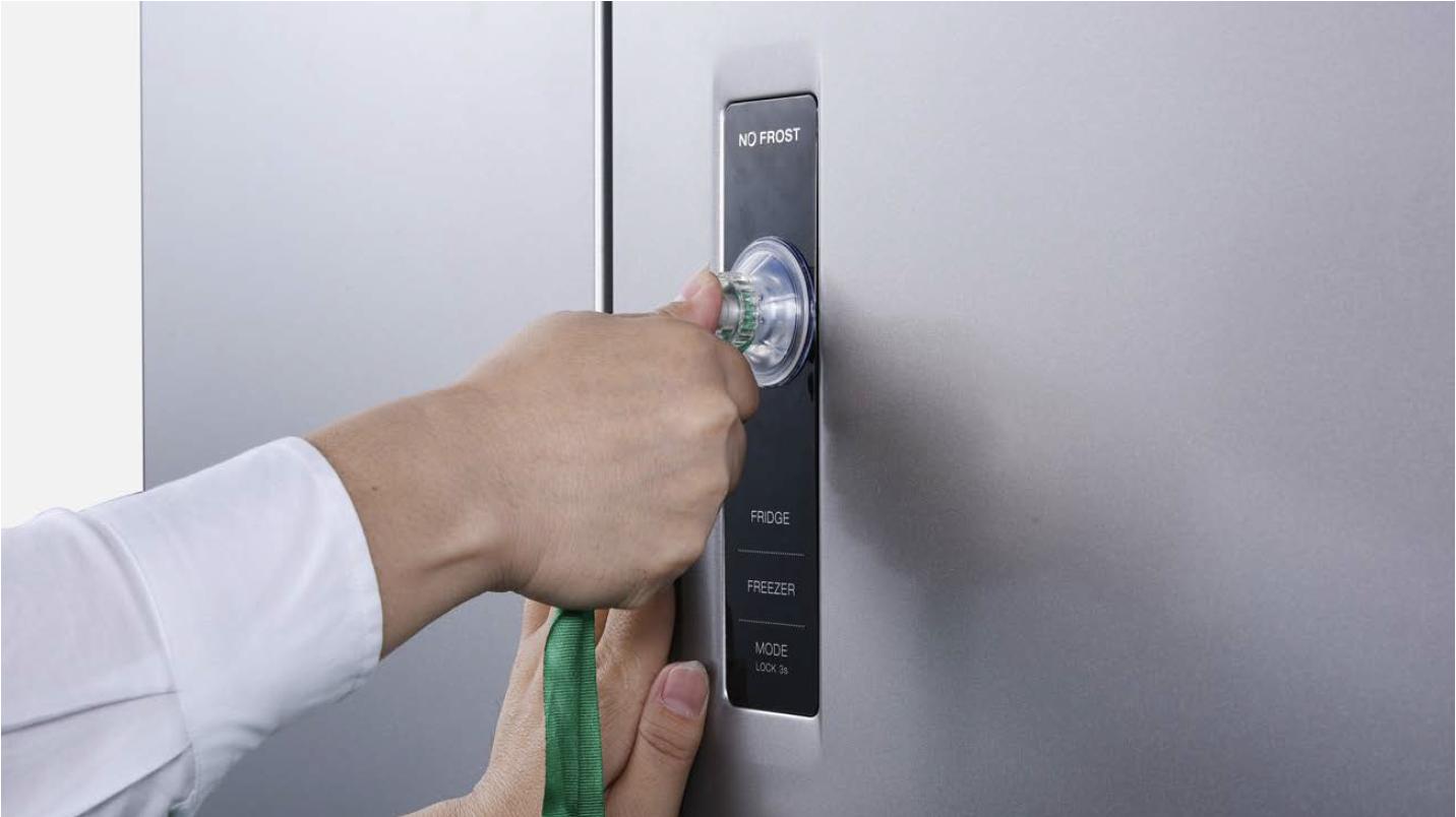
Step 1
Push a 6mm sucker onto display and turn the knob to strengthen suction force.

Step 2
Attach strap to knob to facilitate pulling out display board.
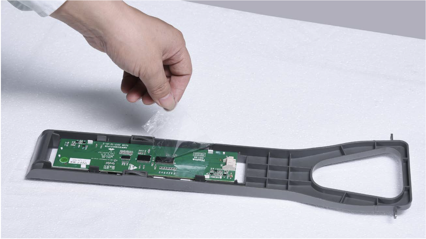
Tips for proper installation of display:
Tip 1
After connecting terminal, please tape wires in place to prevent crushing by the cover.
Tip 2
After inserting display into cavity, press edge until you hear a clicking sound, this means the board is pushed properly into final position.
Please press all buttons on display board to make sure display functions properly.

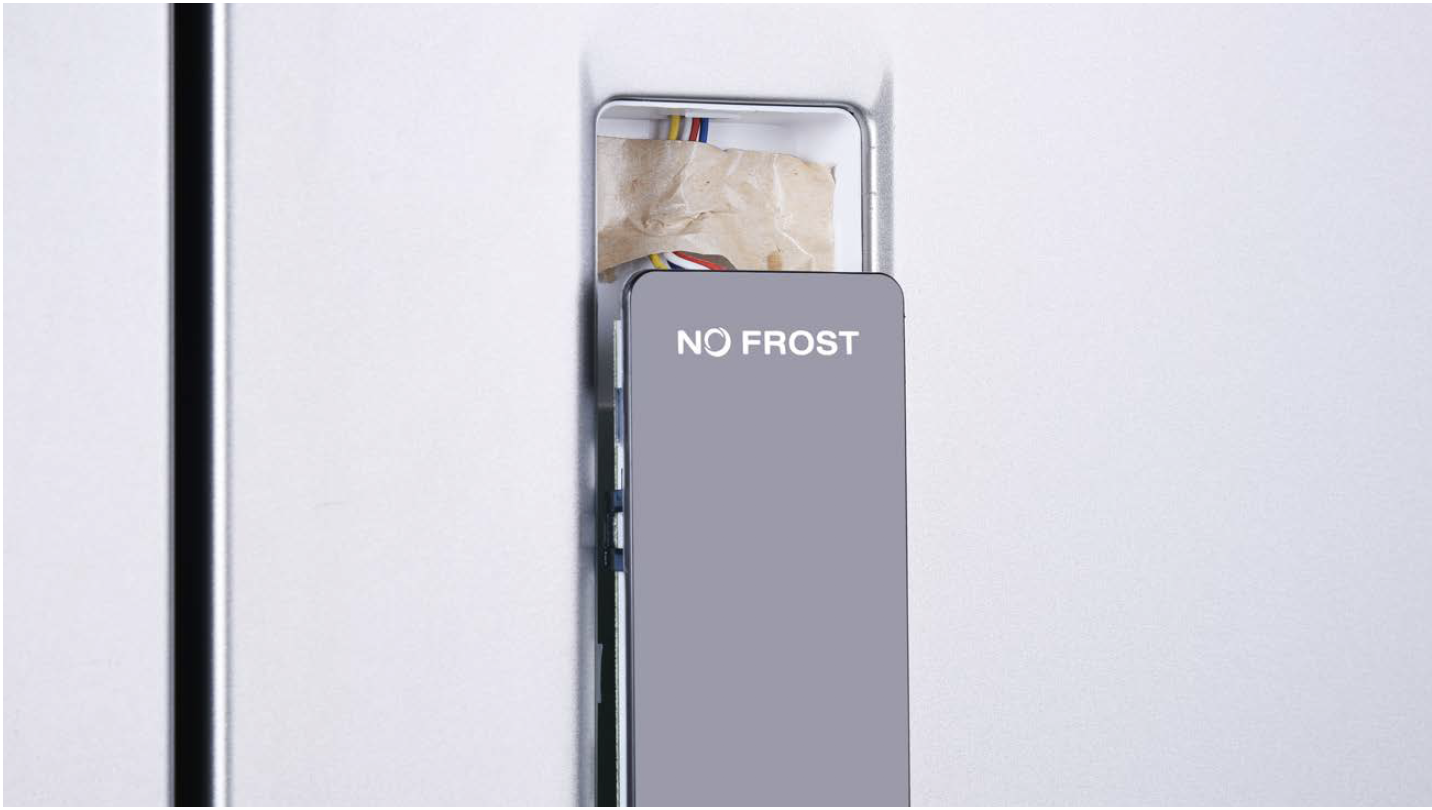
PROCEDURE 4

Step 1
Lever off the cover on door cap.
Step 2
Remove the screws (in total 2).

Step 3
Pull out the plastic;

Step 4
Disconnect the terminal for display panel.

Step 5
Remove tape.
Step 6
Push display out by the corner.

Reverse above steps
to install display
board.
Follow tips carefully:
Tip 1
Please press all buttons on display board to verify if it is working properly. Make sure all words and icons are clear.

PROCEDURE 5

Step 1
Unscrew cover of mainboard with a Cross-head screwdriver.
Step 2
Disconnect terminals.
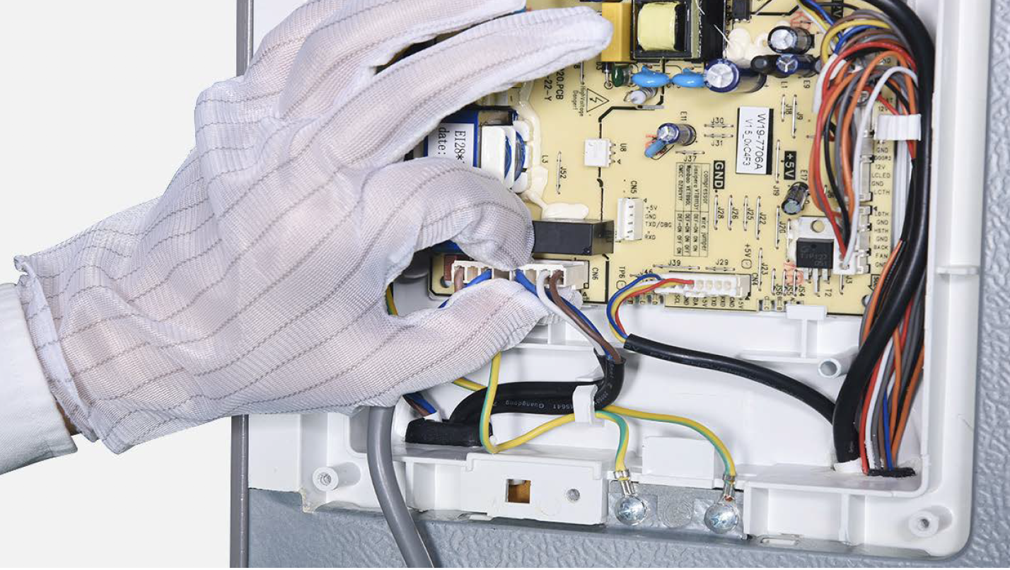
Step 3
Pull out earthing wires.
Step 4
Unscrew the mainboard.
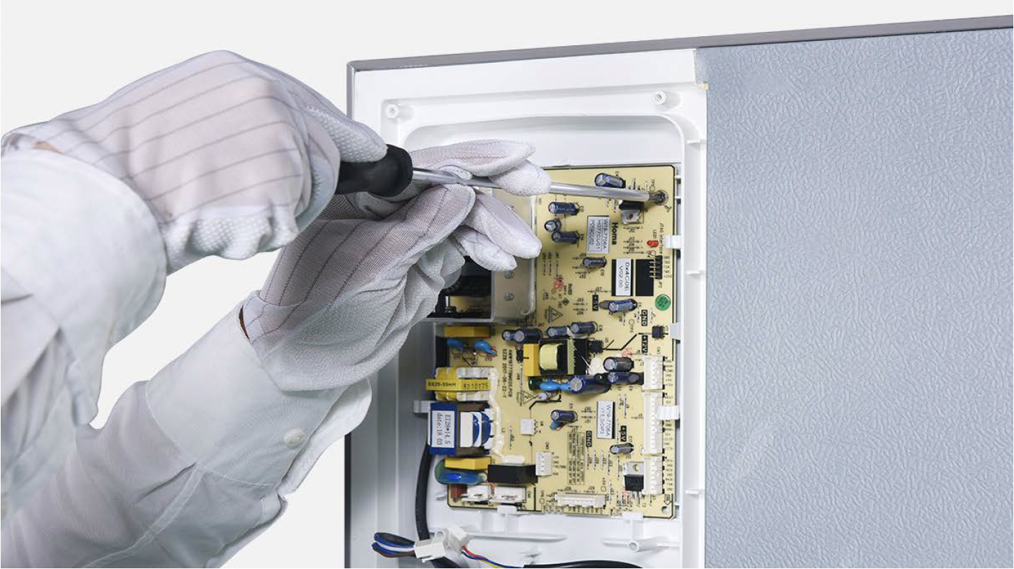
Step 5
Unfasten and remove mainboard.

DIAGNOSIS 5