

CHECK AND TEST 1
Step 1
Unscrew cover of mainboard with a cross-head screwdriver.
Step 2
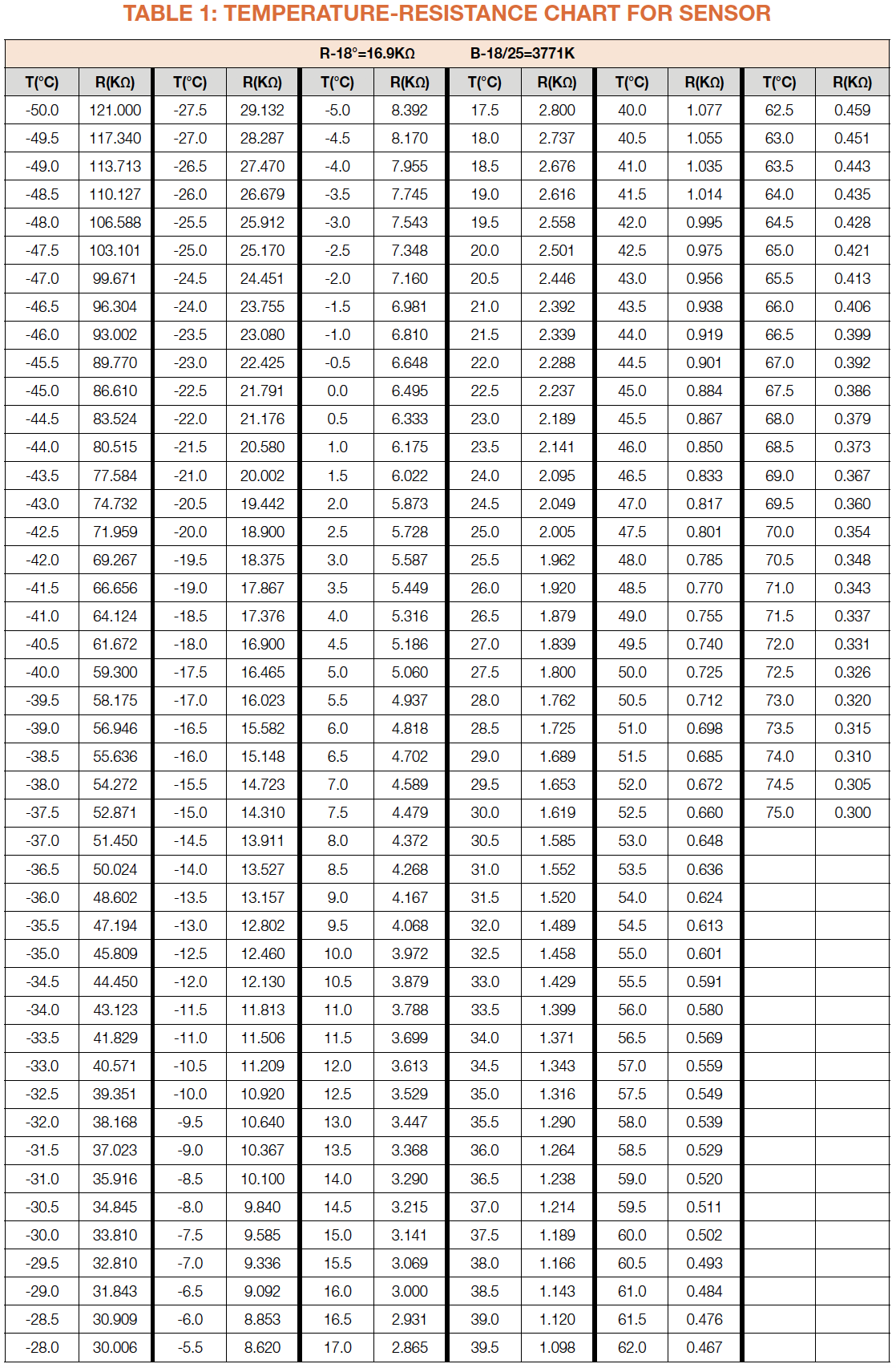
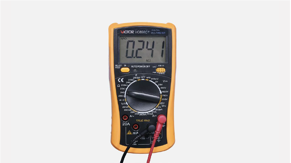
Test resistance of sensor from terminal in PCB area.
Step 3
Step 4
Take note of value.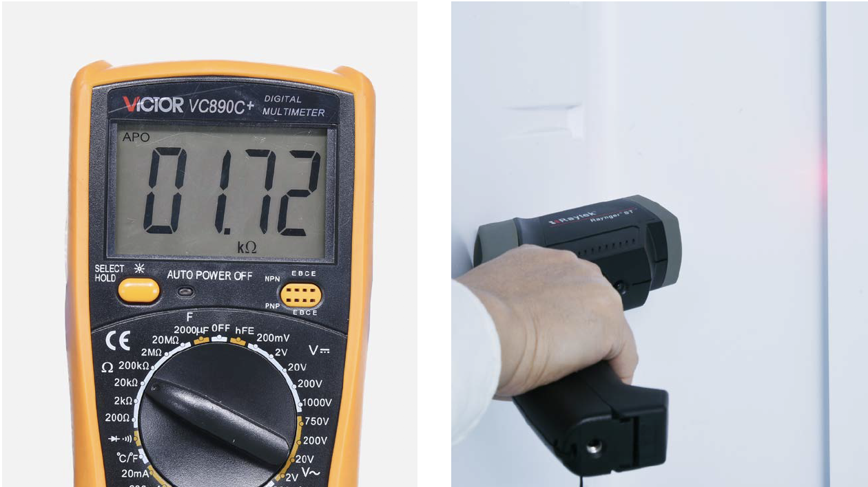
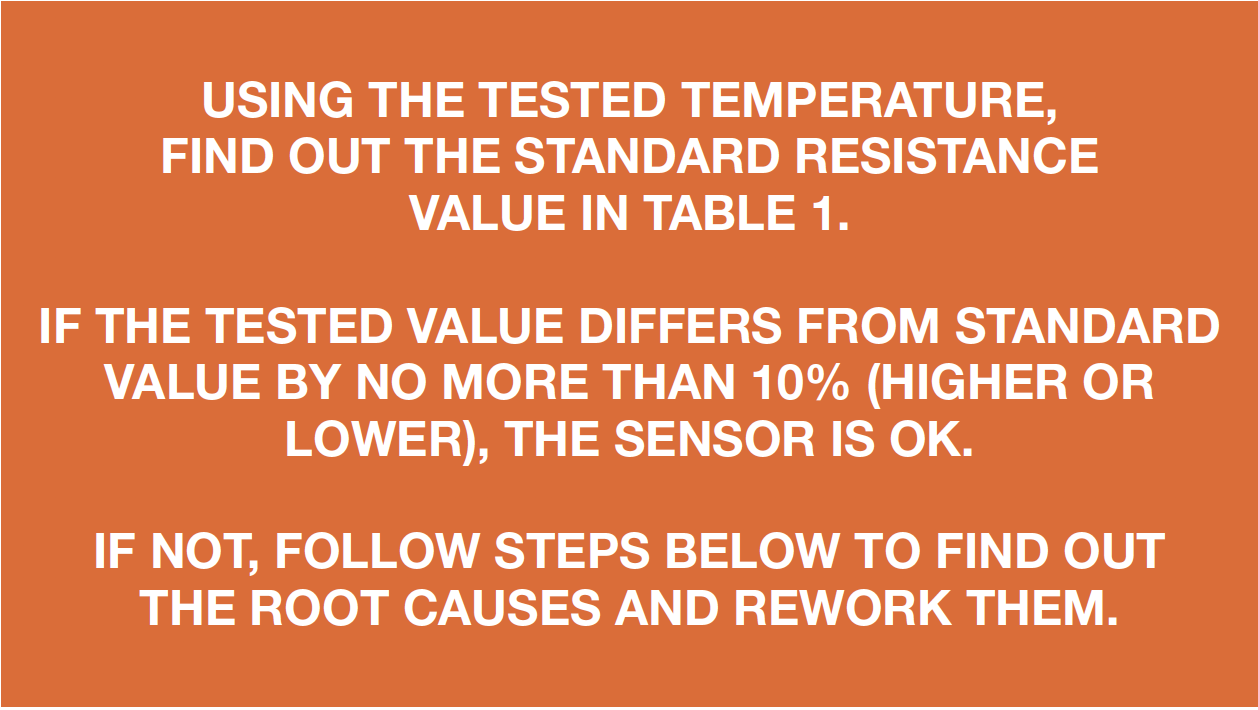
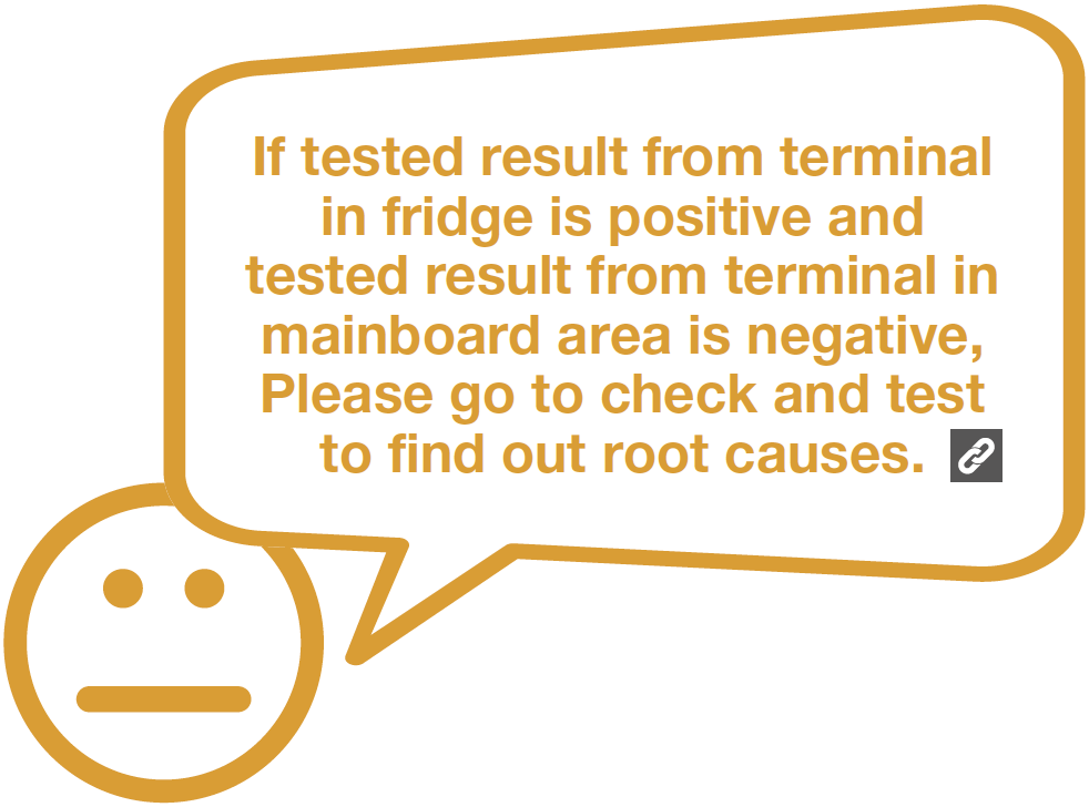
DIAGNOSIS 1


PROCEDURE 1
Step 1
Remove shelves.
Step 2
Remove crispers.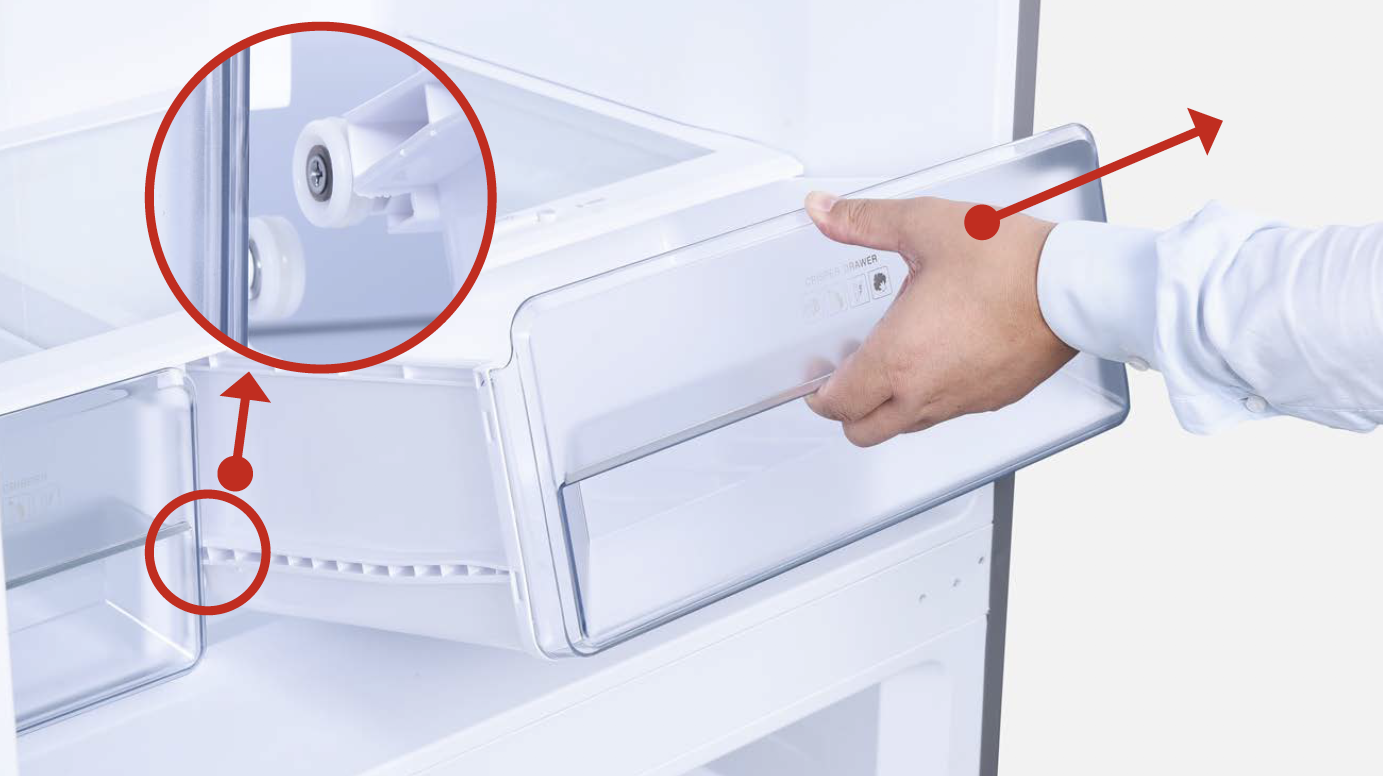
Step 3
Remove shelf cover.
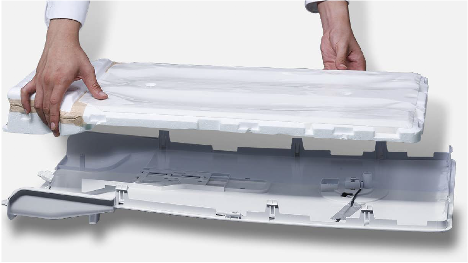
Step 4
Remove partition plate.
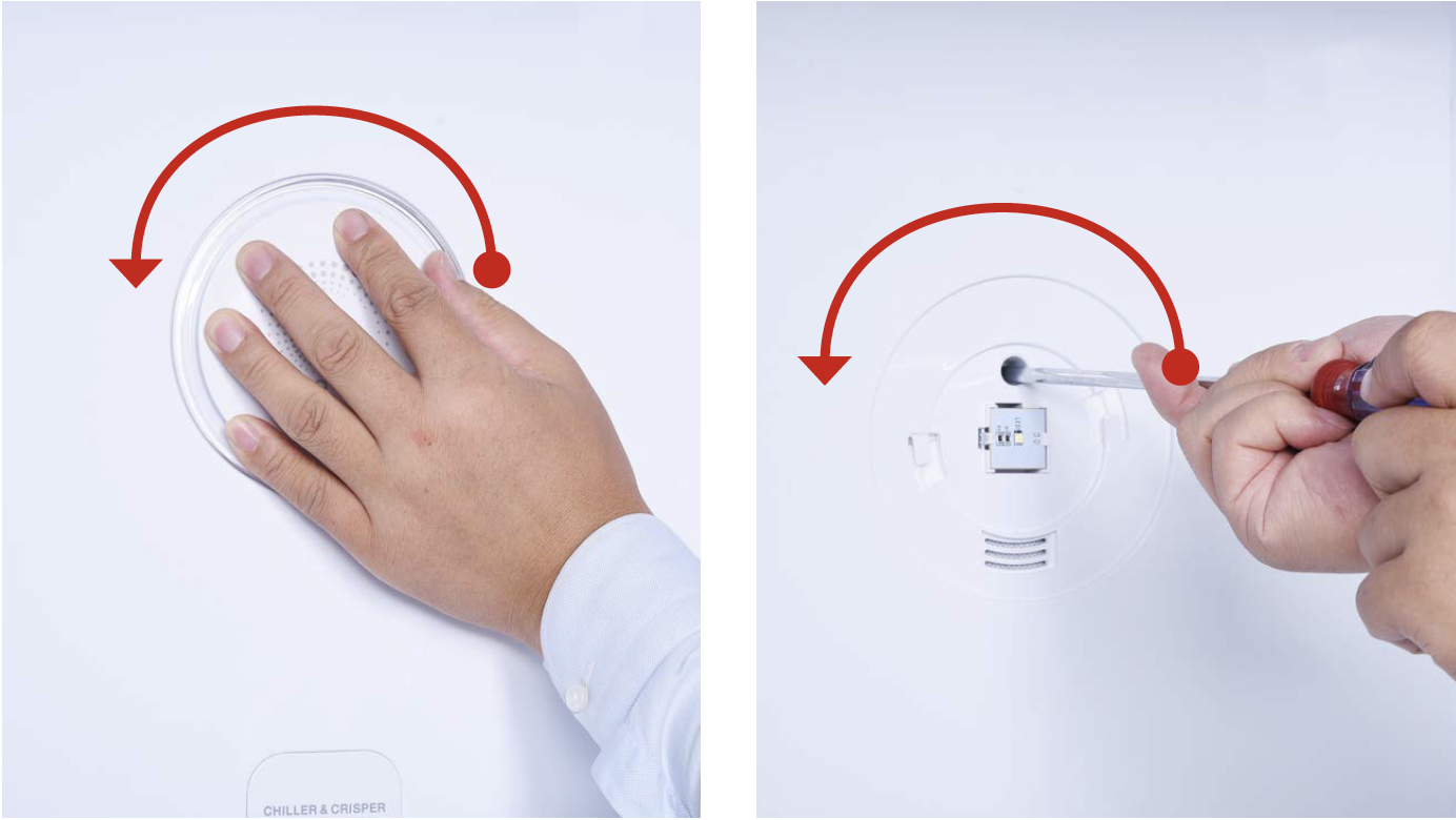
Step 5
Hold the cover and turn in counter-clockwise direction to loosen cover. Then, remove cover.
Step 6
Use 6mm cross-head screwdriver to loosen the screw in counter clockwise direction.
Step 7
Hold the edge of air duct to pull it out.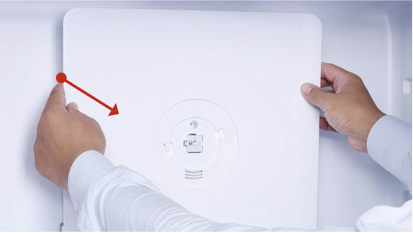
Step 8
Disconnect the terminal for fridge temp. sensor.
CHECK AND TEST 2
Step 1
Test resistance of sensor from terminal in duct cover.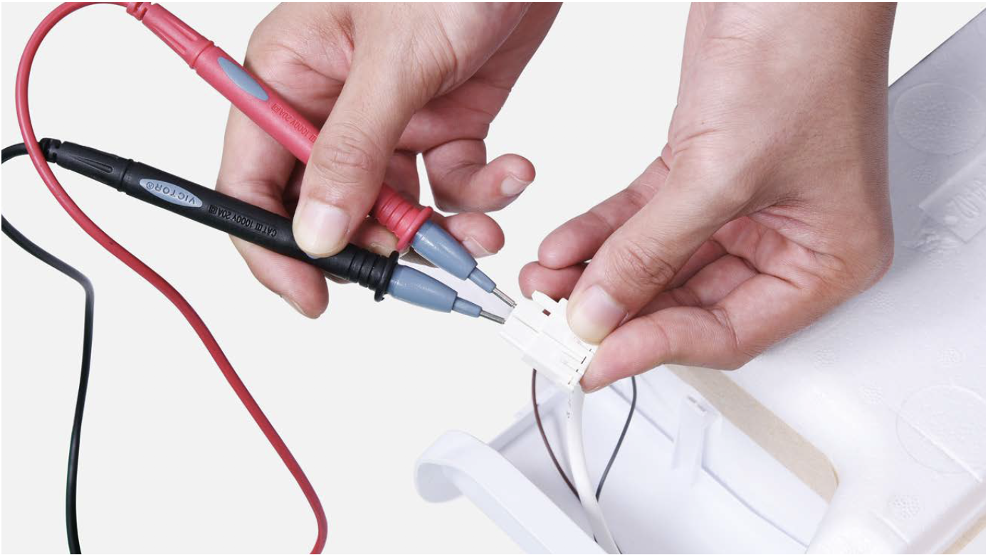
Step 2
Measure temperature of fridge temp. sensor.
DIAGNOSIS 2


Note
PROCEDURE 2
Step 1
Release the clasp.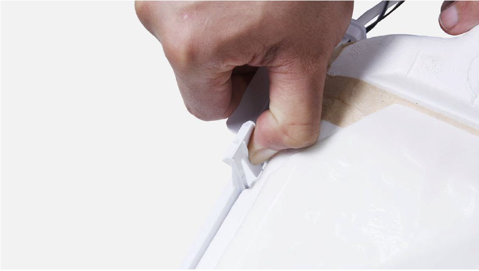
Step 2
Remove the foam air duct.
Step 3
Remove tape.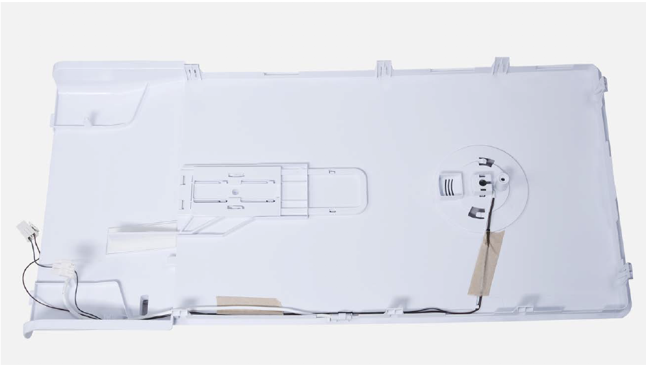
Step 4
Remove the broken sensor.
Note
Reverse the procedures to install new sensor.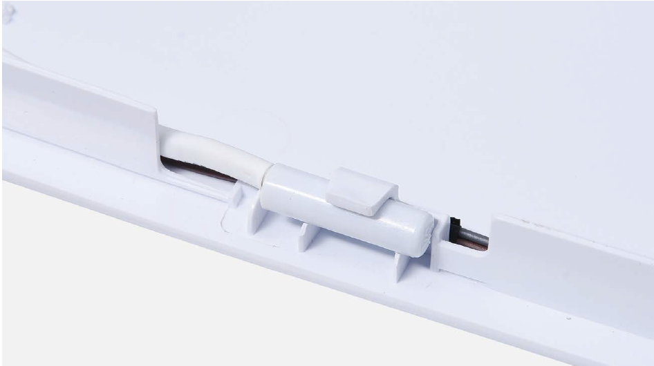
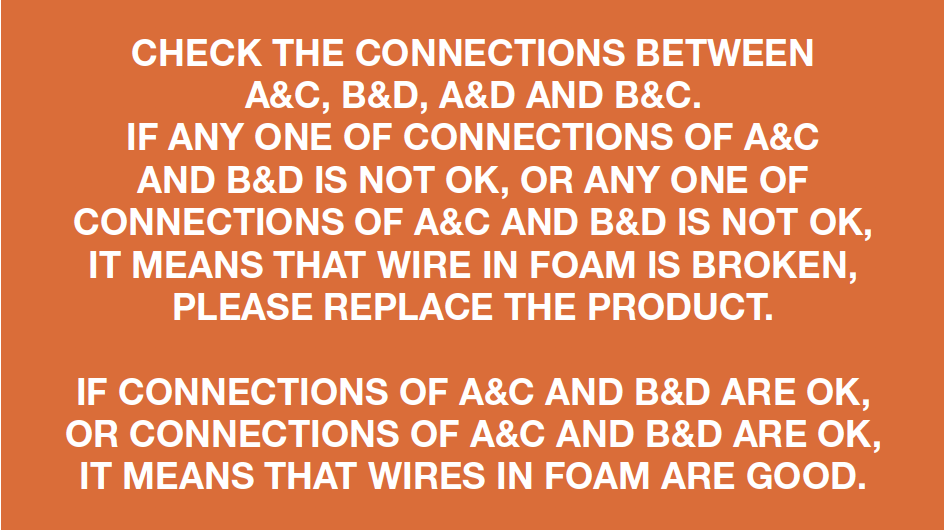
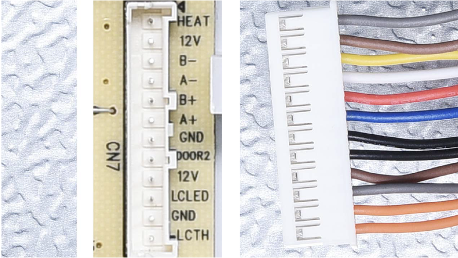
CHECK AND TEST 3
Step 1
Check to see if terminal is full of foam.
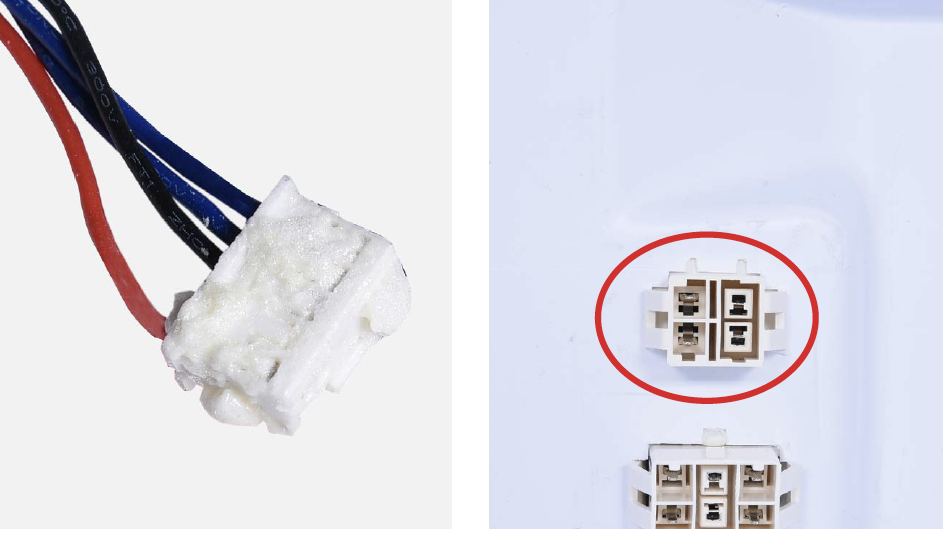
Step 2
Use tweezers or tools with sharp tip to remove foam in terminal.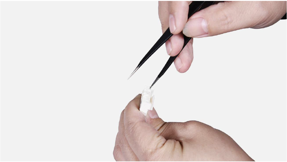
Step 3
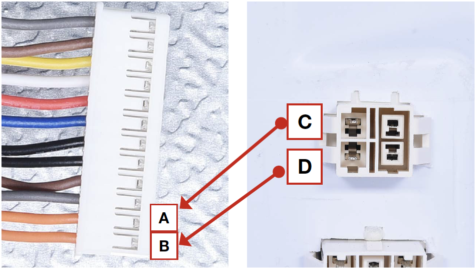
Check to ensure that wires are connected properly.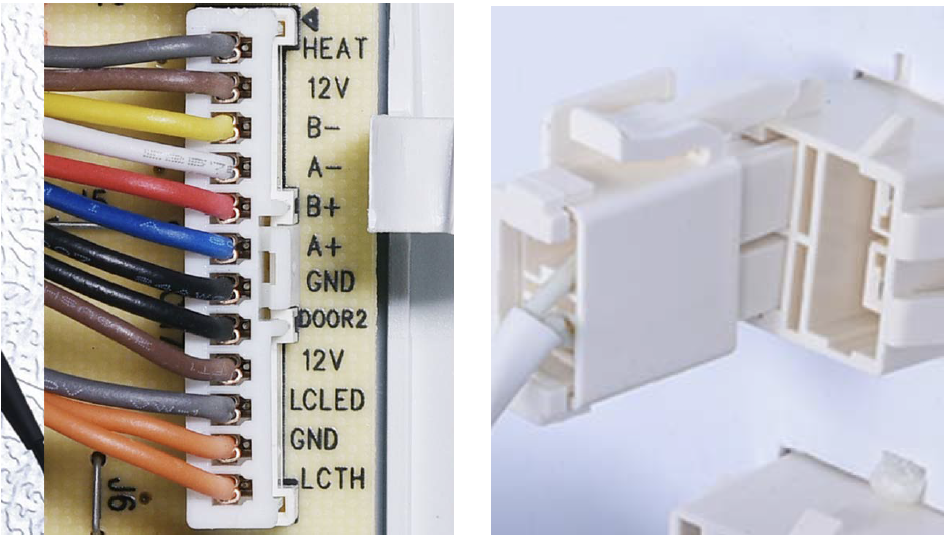
Step 4
Use multimeter to test connections.1. Put detector into one end of wires in PCB area;
2. Put another detector into end of wires behind air duct.
DIAGNOSIS 3


PROCEDURE 3

Step 1
Reinsert the terminals for sensor.Make sure that the terminal is pushed into final position.
Step 2
Screw on the cover of mainboard with a cross-head screwdriver.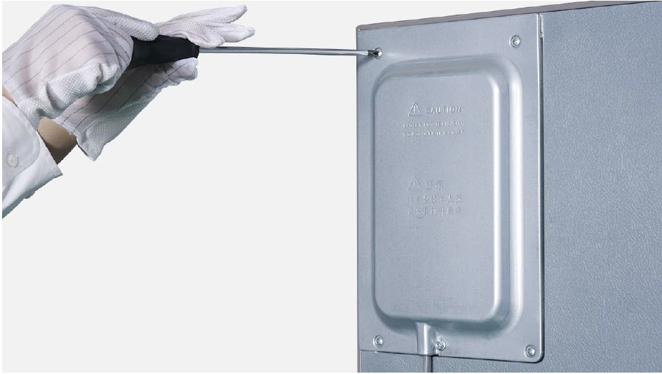
Step 3
Re-connect the terminals.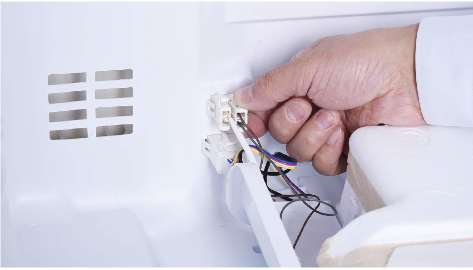
Step 4
Hold air duct by edges to put it back in place.
Step 5
Use a 6mm cross-head screwdriver to tighten the screw clockwise.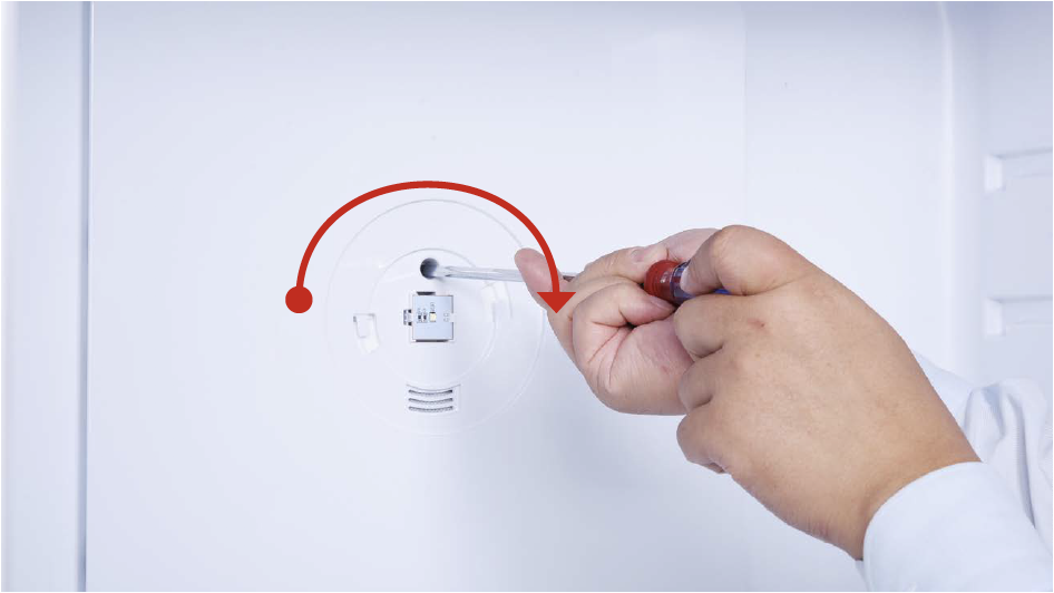
Step 6
Hold the cover and turn it clockwise to tighten the lid, then move it backwards.
Step 7
Insert partition plate.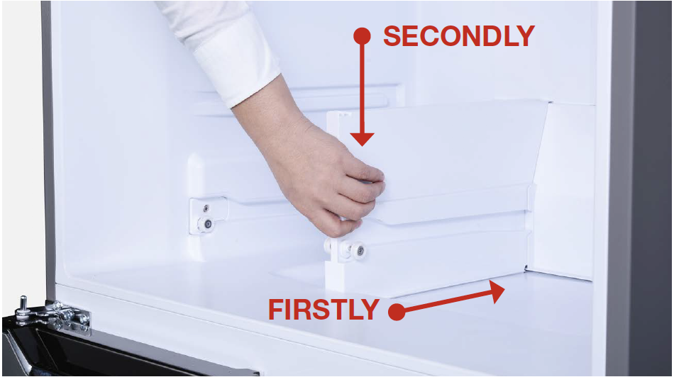
Step 8
Insert shelf cover.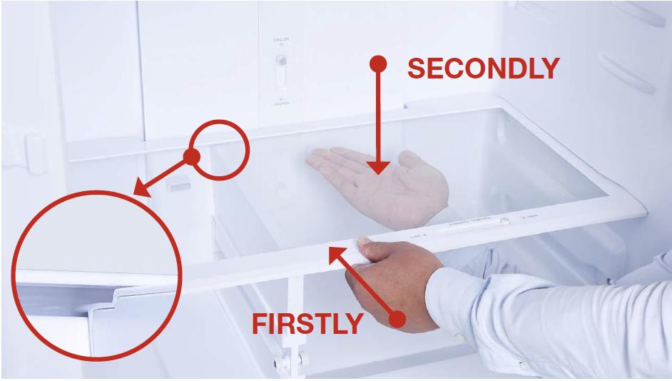
Step 9
Insert crispers.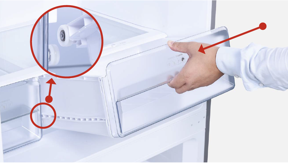
Step 10
Insert shelves.
TIPS DURING INSTALLATION PROCEDURES FOR FRIDGE AIR DUCT.
Tip 1
Connect the terminals.

Tip 2
Push terminals into place, then move wires to prevent crushing of wires with edge of air duct.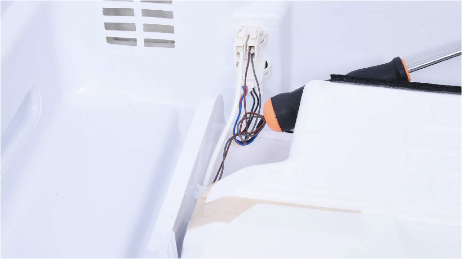
Tip 3
When reinstalling the air duct, frist insert positive shaft into negative hole.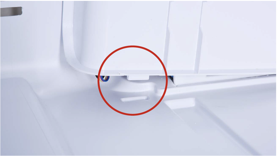
Tip 4
Then, fasten the clasp on top using the same method.
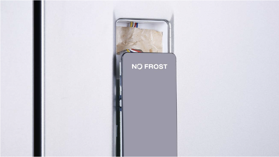
DIAGNOSIS 4

PROCEDURE 4

Step 1
Push a 6mm sucker onto display and turn the knob to strengthen suction force.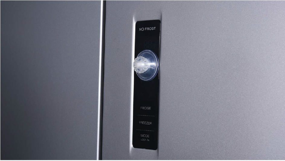
Step 2
Attach strap to knob to facilitate pulling out display board.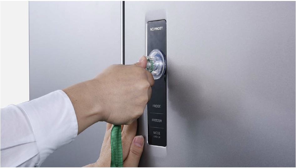
Tips for proper installation of display:
Tip 1
After connecting terminal, please tape wires in place to prevent crushing by the cover.
Tip 2
After
inserting display into cavity, press edge until you hear a clicking
sound, this means the board is pushed properly into final position.
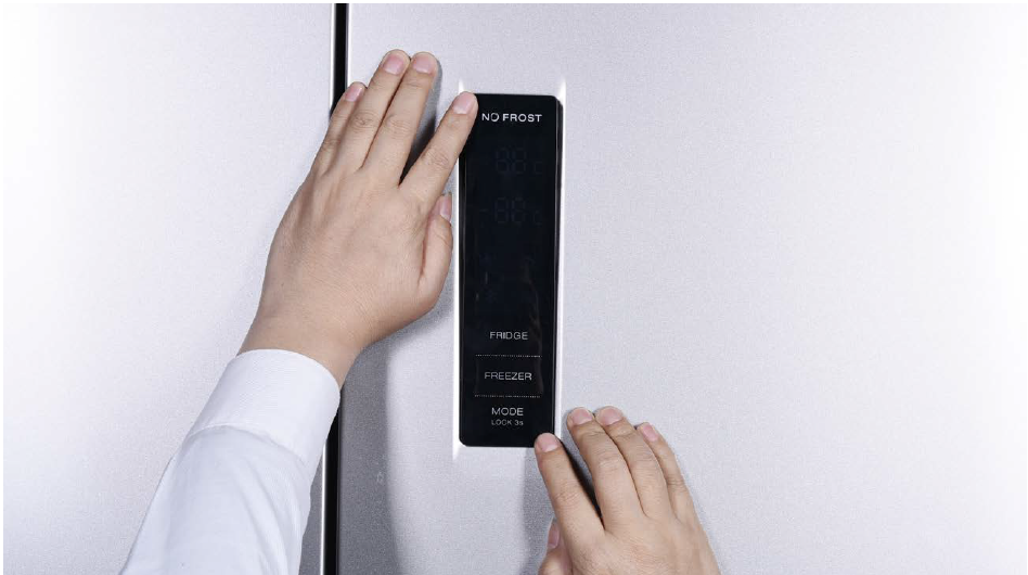
Please press all buttons on display board to make sure display functions properly.
PROCEDURE 5

Step 1
Lever off the cover on door cap.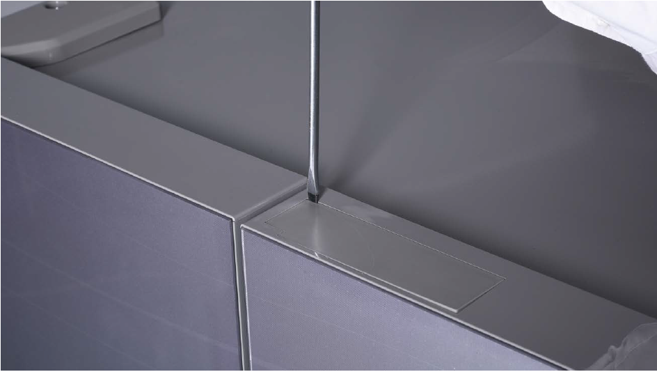
Step 2
Remove the screws (intotal 2).
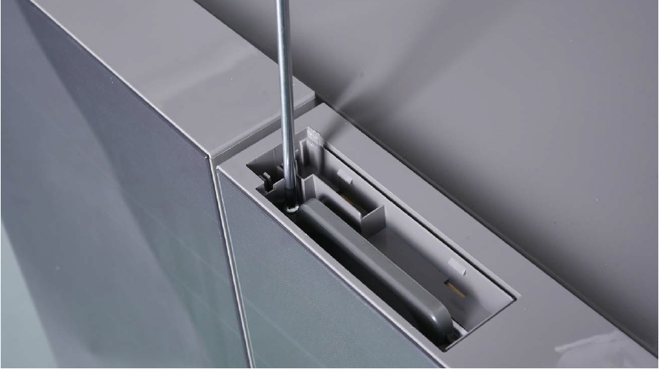
Step 3
Pull out the plastic;
Step 4
Disconnect the terminal for display panel.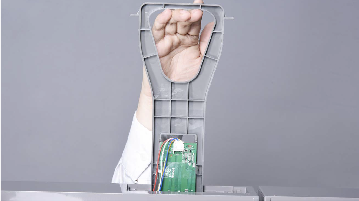
Step 5
Remove tape.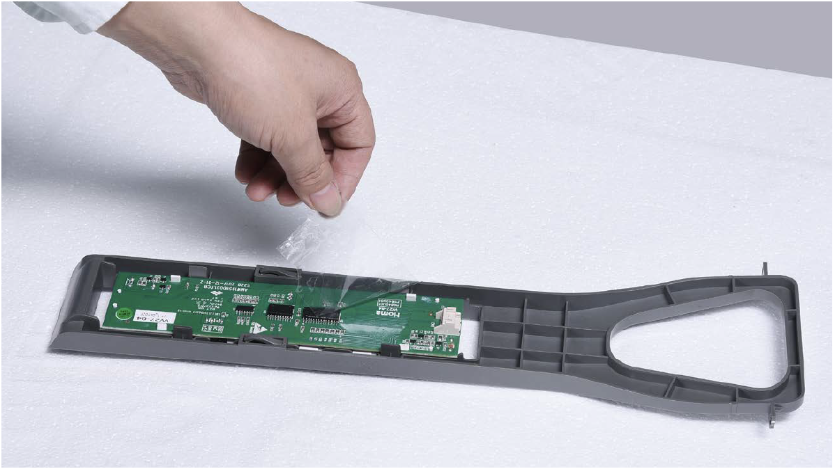
Step 6
Push display out by the corner.
Reverse above steps to install display board. Follow tips carefully:
Tip 1
Please press all buttonson display board to verify
if it is working properly.
Make sure all words and
icons are clear.

PROCEDURE 6

Step 1
Unscrew cover of mainboard with a Cross-head screwdriver.
Step 2
Disconnect terminals.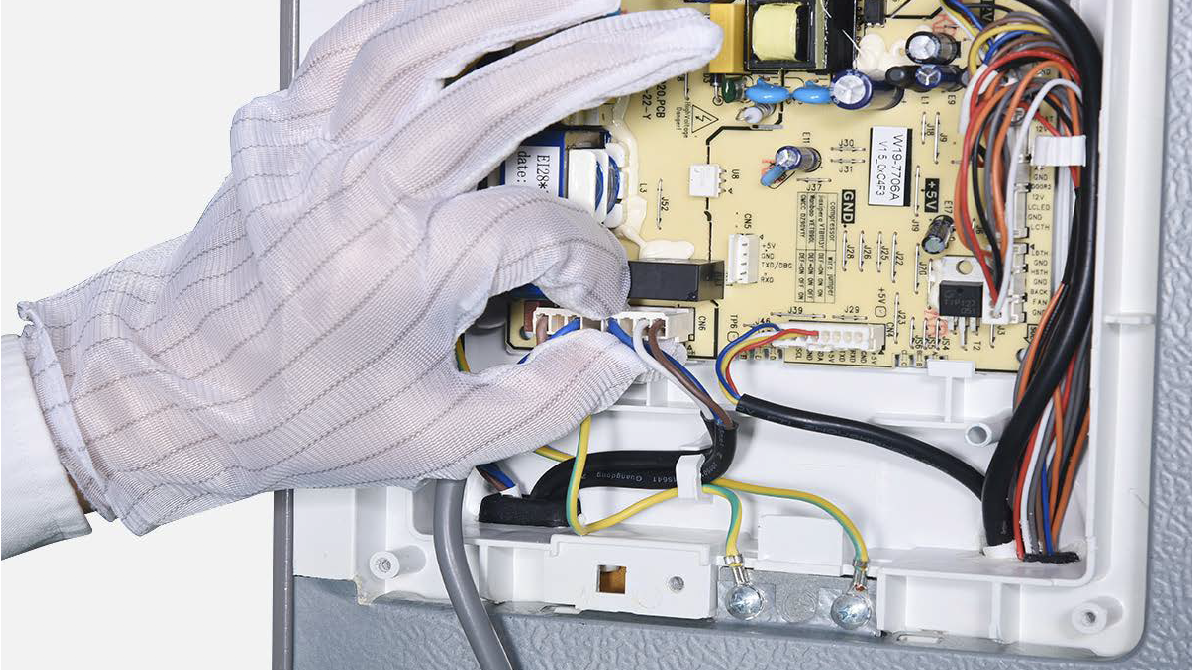
Step 3
Pull out earthing wires.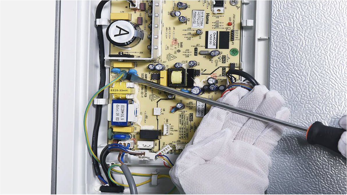
Step 4
Unscrew the mainboard.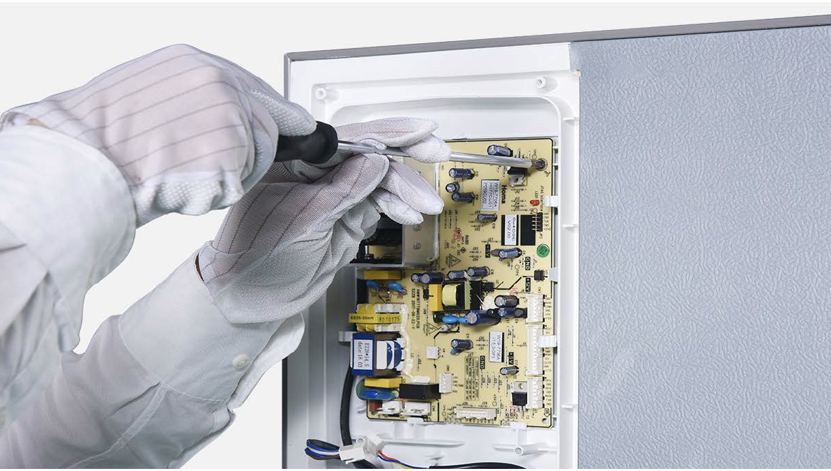
Step 5
Unfasten and remove mainboard.
DIAGNOSIS 5


GO BACK TO COMPONENT LIST