

CHECK AND TEST 1
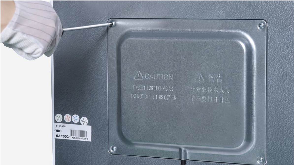
Step 1
Unscrew cover of mainboard with a Cross-head screwdriver.
Step 2
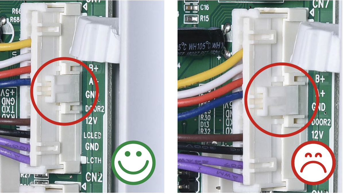
In mainboard area, check if terminal is pushed into proper final position.
Step 3
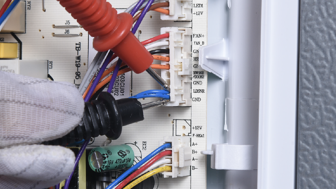
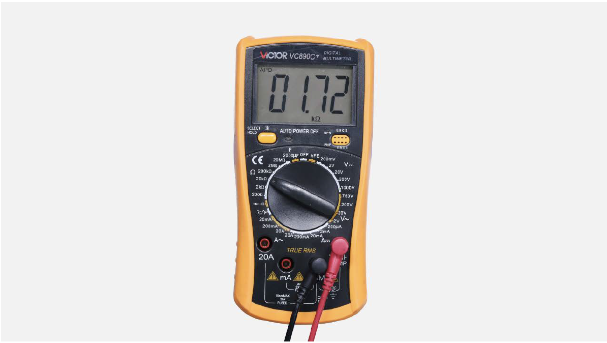
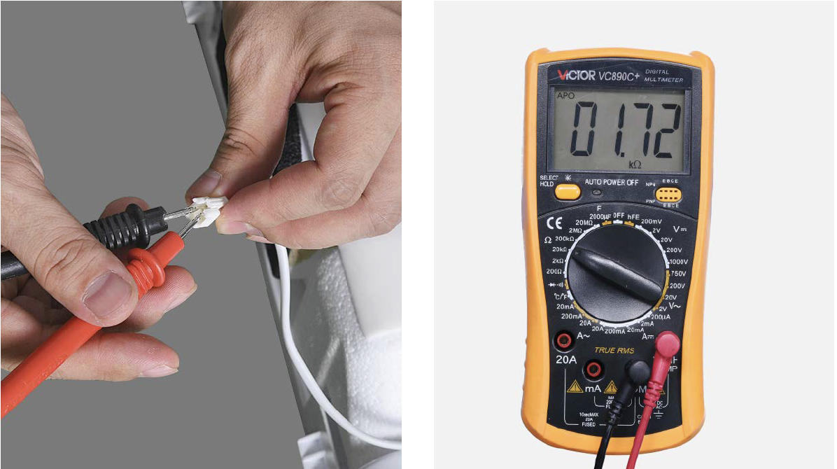
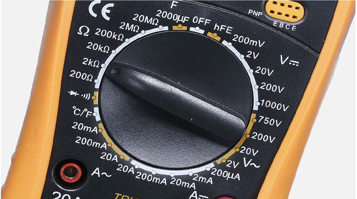
Set multimeter to resistance gear.

Step 4
Measure resistance of fridge temp. sensor from terminal in PCB area.
Step 5
Take note of value.
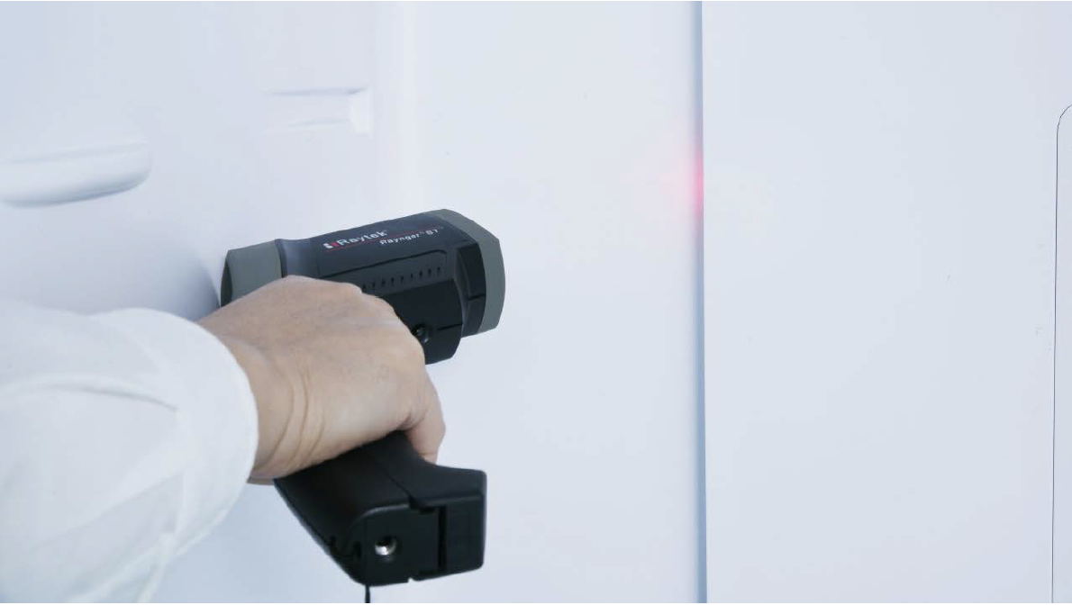
Step 6
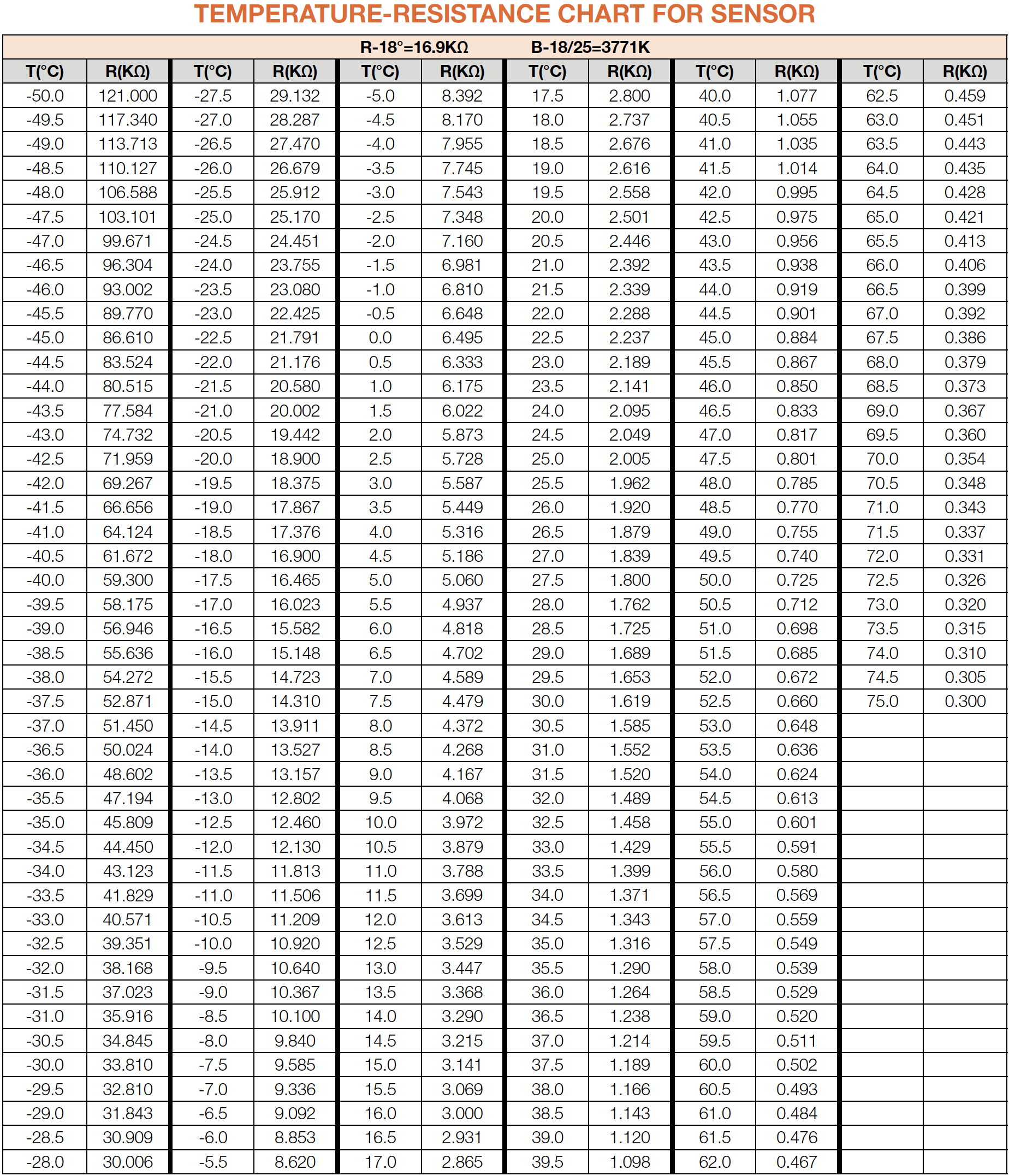
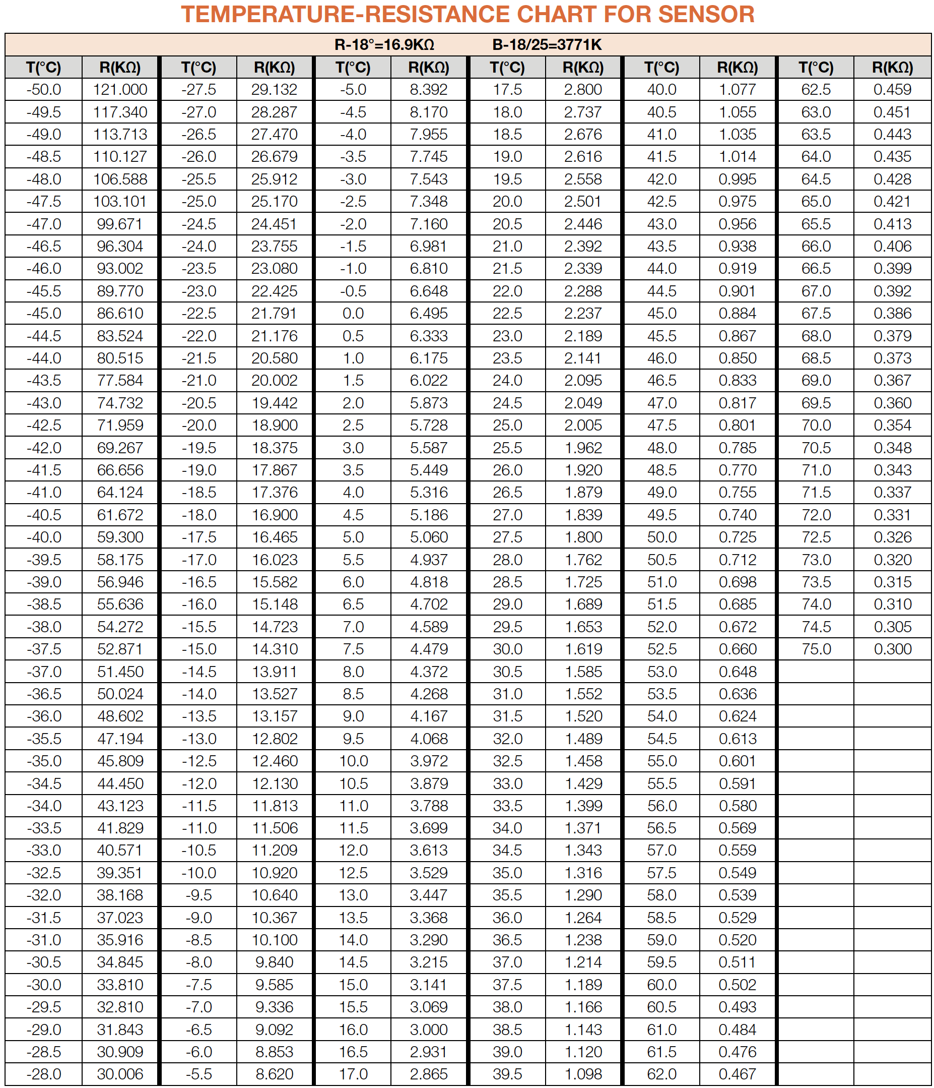
Measure the temperature of fridge temp. sensor. Use the measured temperature to find the standard resistance value in Temperature- Resistance Chart for Sensor.

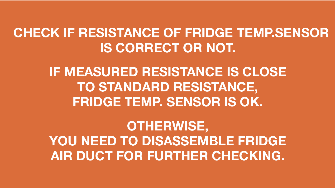
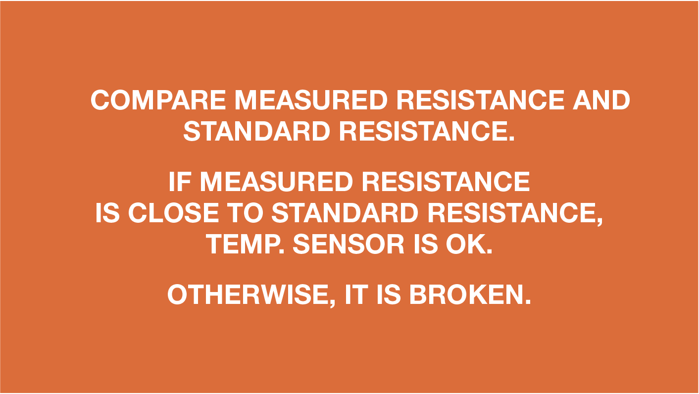
DIAGNOSIS 1
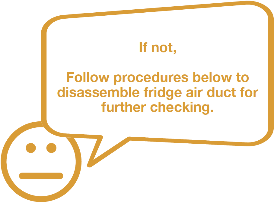

PROCEDURE 1
Step 1
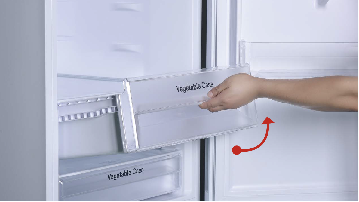
Remove crispers.
Step 2
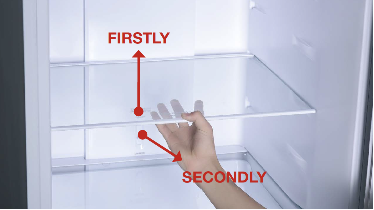
Remove shelves.
Step 3
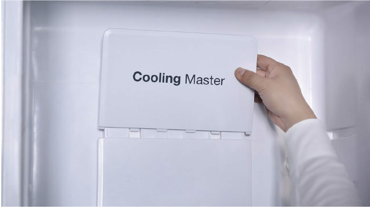
Loosen the decorative plate and remove.
Step 4
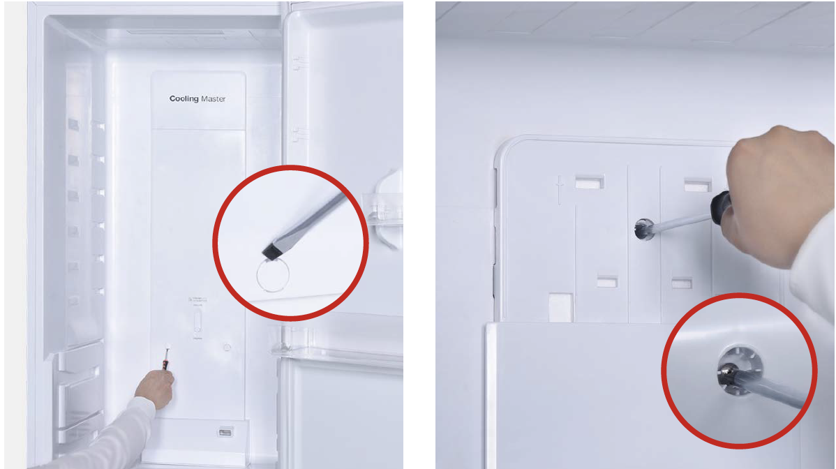
Remove the screw covers on the air duct with slotted screw driver.
Step 5
Unscrew the screws (total of three) with Cross-head screw driver.
Step 6
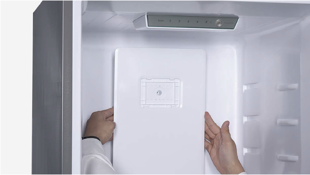
Lift the air duct up slightly and pull it out.
CHECK AND TEST 2
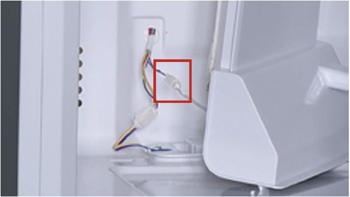
Step 1
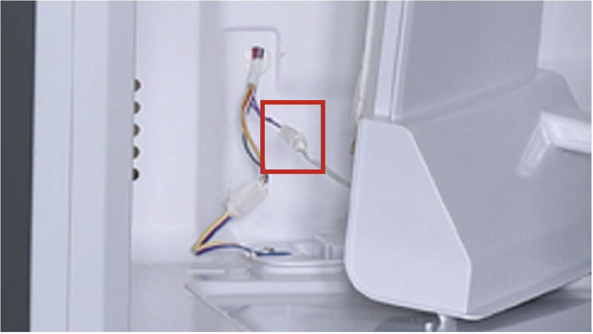
Check if terminal is properly inserted to final position.
If not, reinsert it.
Step 2
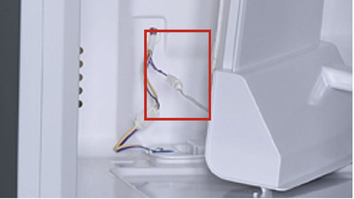
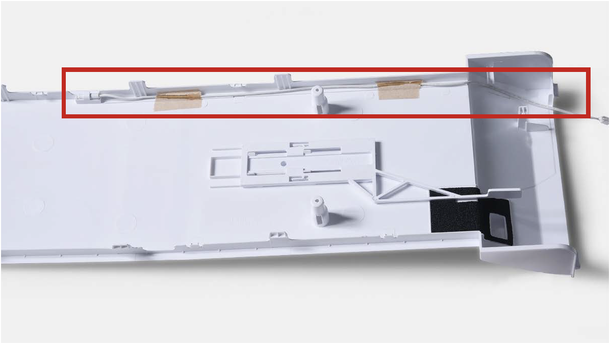
Check if wires of fridge temp. sensor are damaged or not.
PROCEDURE 2
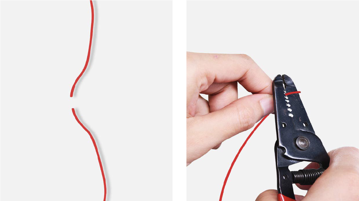
Step 1
Cut wire off.
Step 2
Peel off the sleeves.
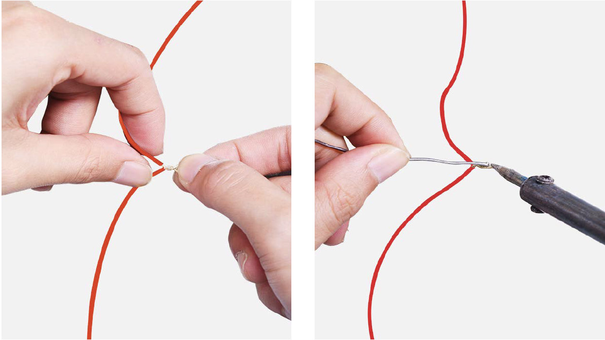
Step 3
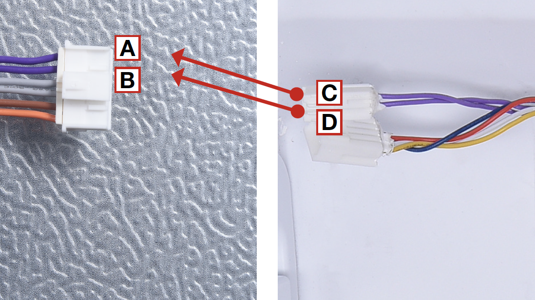
Check to ensure proper wire order and reconnect them.
Step 4
Tin soldering.
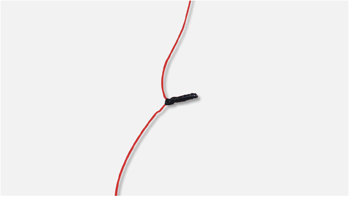
Step 5
Cover connecting point with electrical tape.
CHECK AND TEST 3
Step 1
Disconnect terminal of fridge temp. sensor.
Step 2
Measure resistance of fridge sensor from terminal in fridge air duct cover.
Step 3
Measure the temperature of fridge temp. sensor. Use the measured temperature to find the standard resistance value in Temperature- Resistance Chart for Sensor.
DIAGNOSIS 3
PROCEDURE 2
Step 1
Release the clasp.
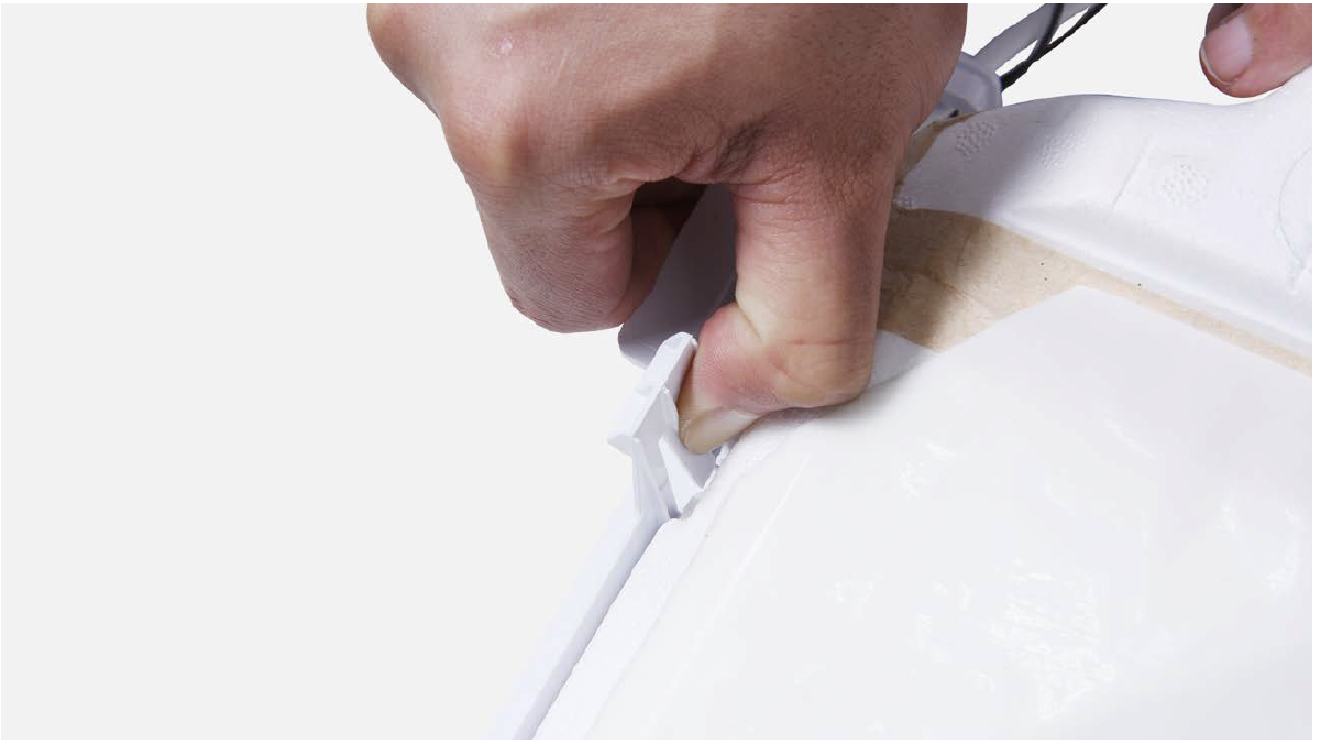
Step 2
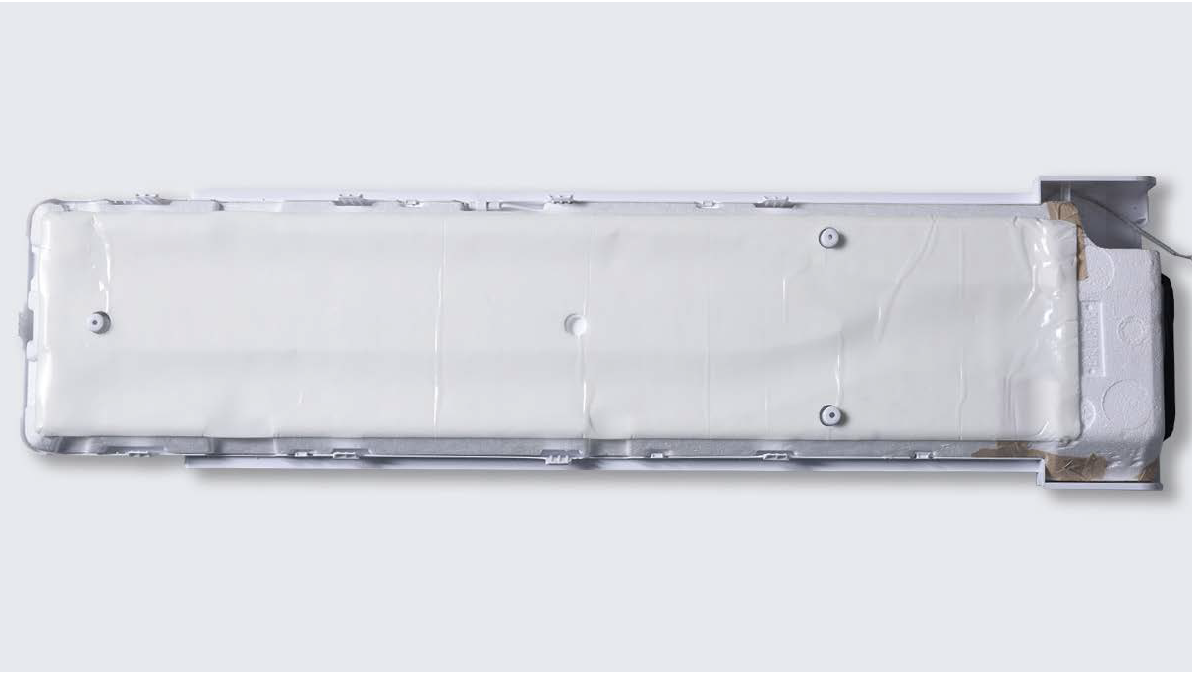
Remove the foam air duct.
Step 3
Remove tape.
Step 4
Remove the broken
sensor, and replace it
with a new one.
Reverse steps above to reinstall the air duct.
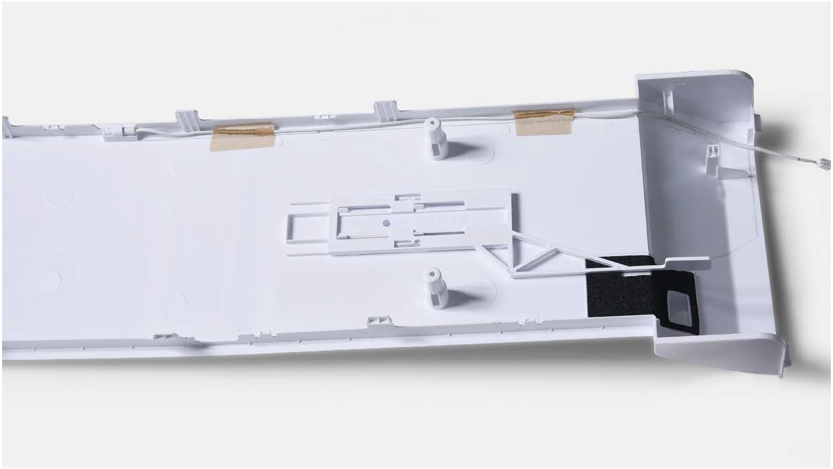
Please pay attention to bellow key points.
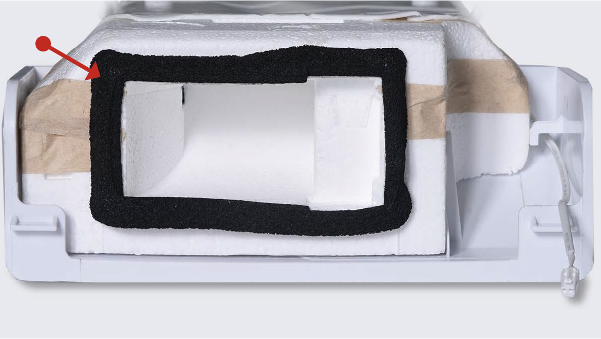
Tip 1
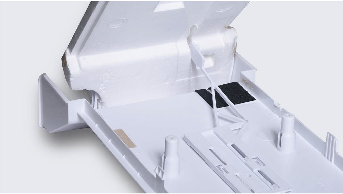
Attach the sensor properly onto air duct cover, as picture in right.

Tip 2
Make sure the sealing sponge is in good condition.
Tip 3
Make sure back cover of the air duct is not broken.
Tip 4
Make sure chiller temperature controller is installed to correct position.
CHECK AND TEST 4
Step 1
Set multimeter to resistance gear.
Step 2
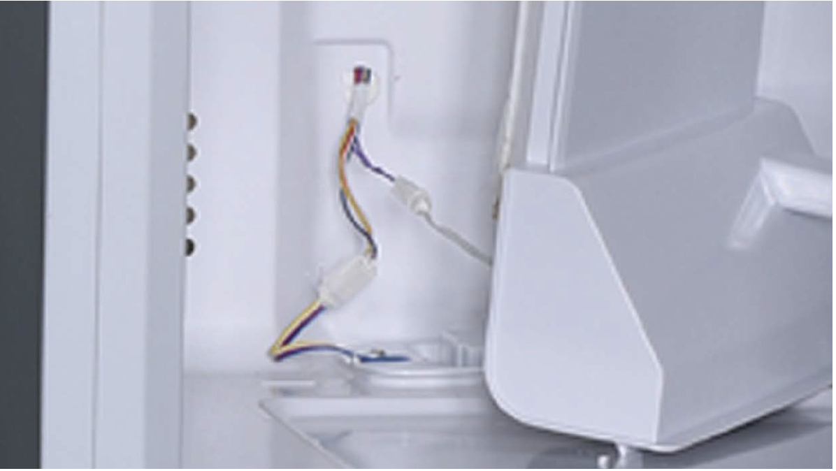
Put one detector into one end of wires in PCB area, and another detector into one end of wires in fridge air duct cover.
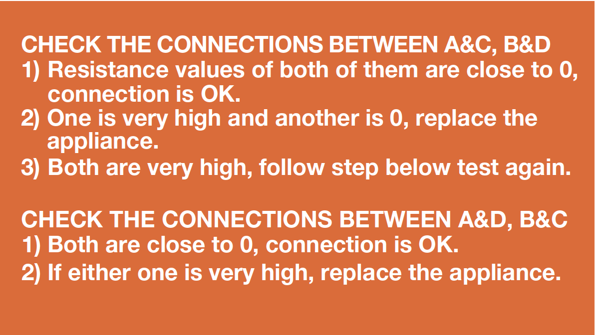
DIAGNOSIS 4

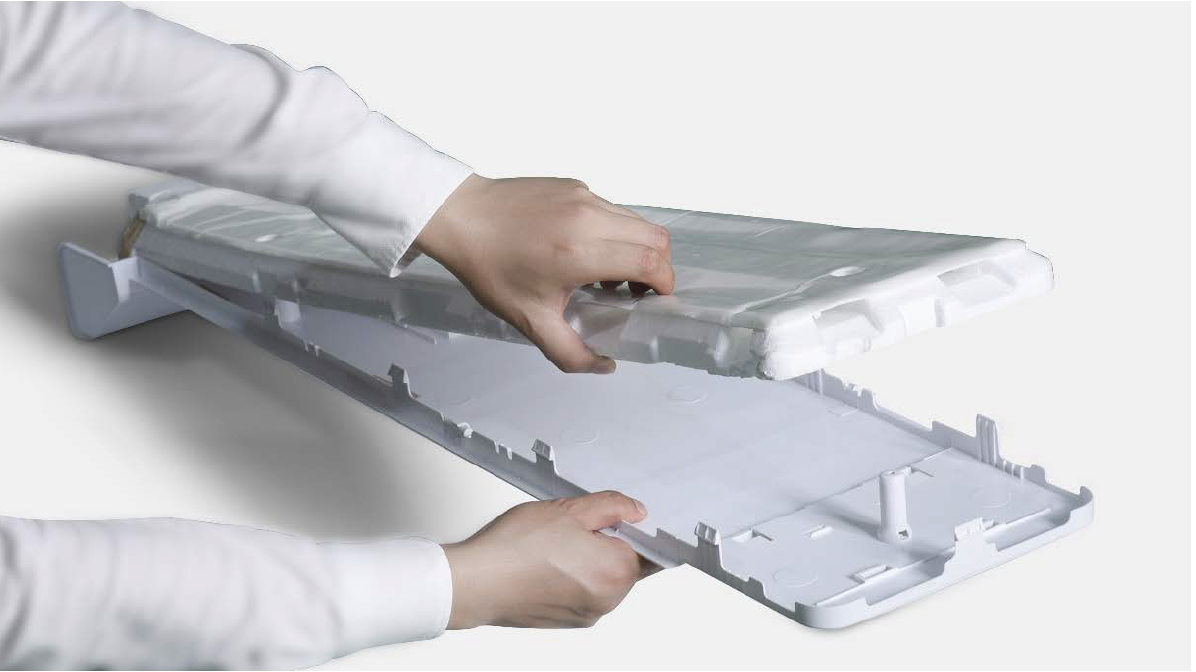
PROCEDURE 3
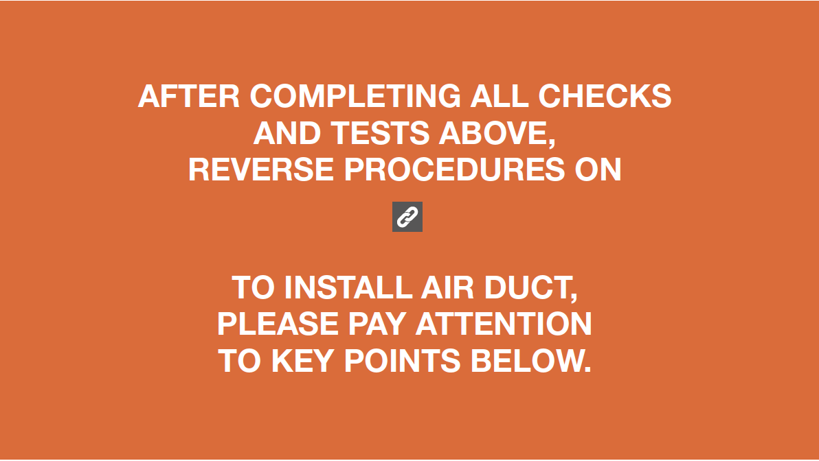
Tip 1
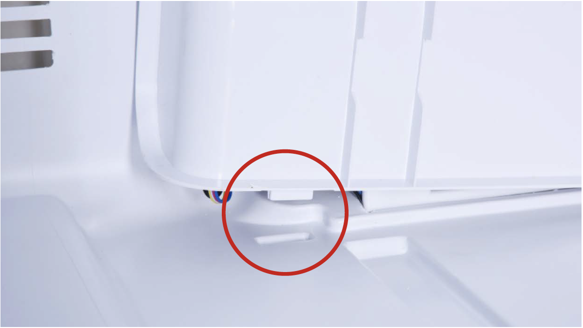
Push terminals into final position, and then move wires onto cavity to avoid crushing wires with edge of air duct.
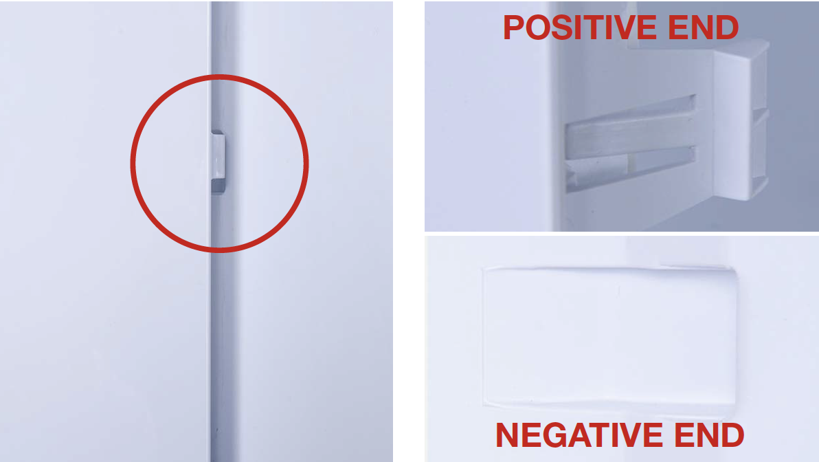
Tip 2
When reinstalling the air duct, first put the positive end of buckle (on the bottom) into the negative end.
Tip 3
Later, fasten the buckles on the top with same method.
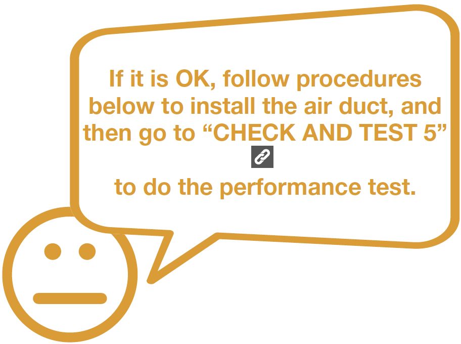
CHECK AND TEST 5

DIAGNOSIS 5


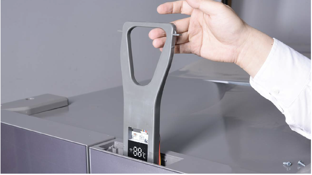
PROCEDURE 4

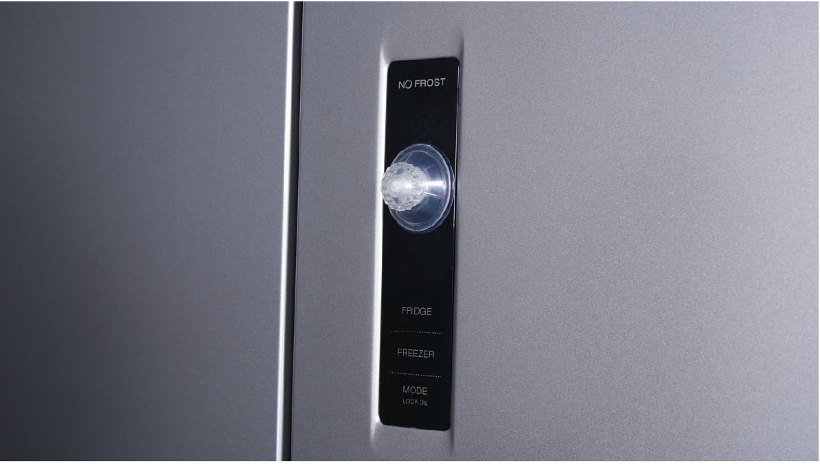
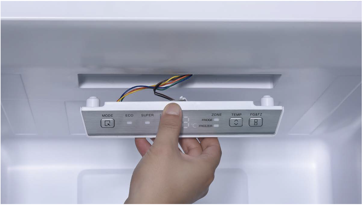
Step 1
Push a 6mm sucker onto display and turn the knob to strengthen suction force.
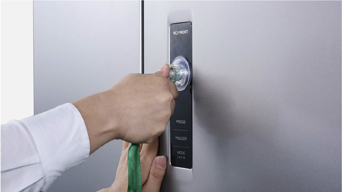
Step 2
Wrap a belt around knob to make it easier to pull out of display board.
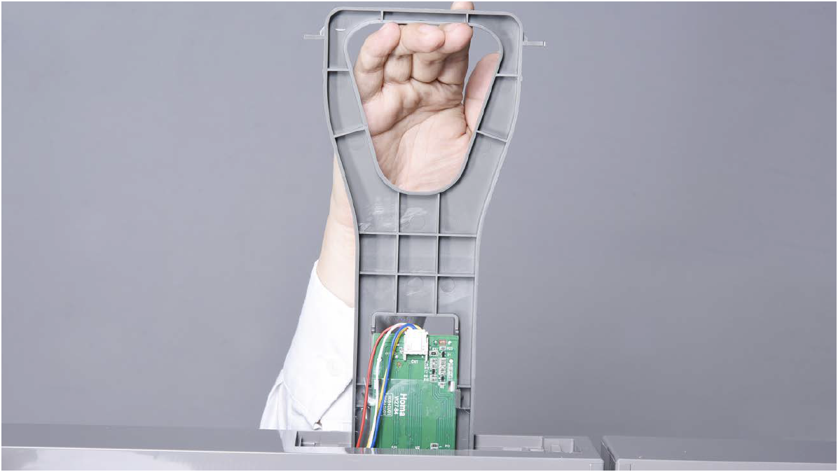
Tips for installing display.
Tip 1
After connecting terminal, please use tape to fasten wires to avoid crushing with cover.
Tip 2
After putting display
into cavity, press edge
until you hear a clicking
sound, this means the
board is pushed into final
position.
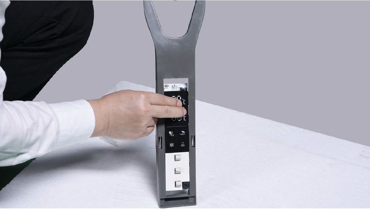
Tip 3
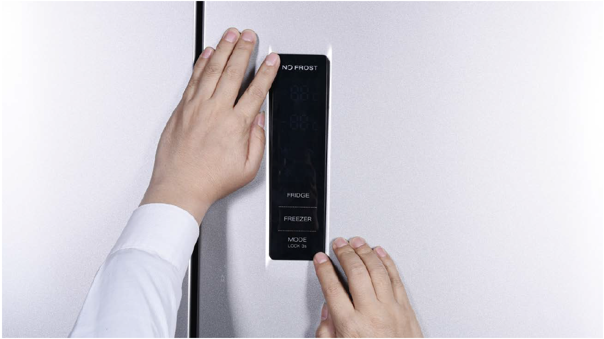
Please press all buttons on display board to make sure it works well.
PROCEDURE 5
Step 1
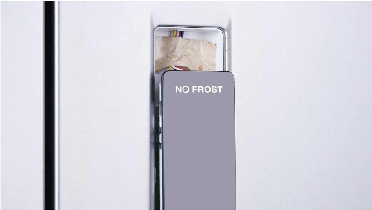
Prize off the cover on door cap.
Step 2
Remove the screws (in total 2).
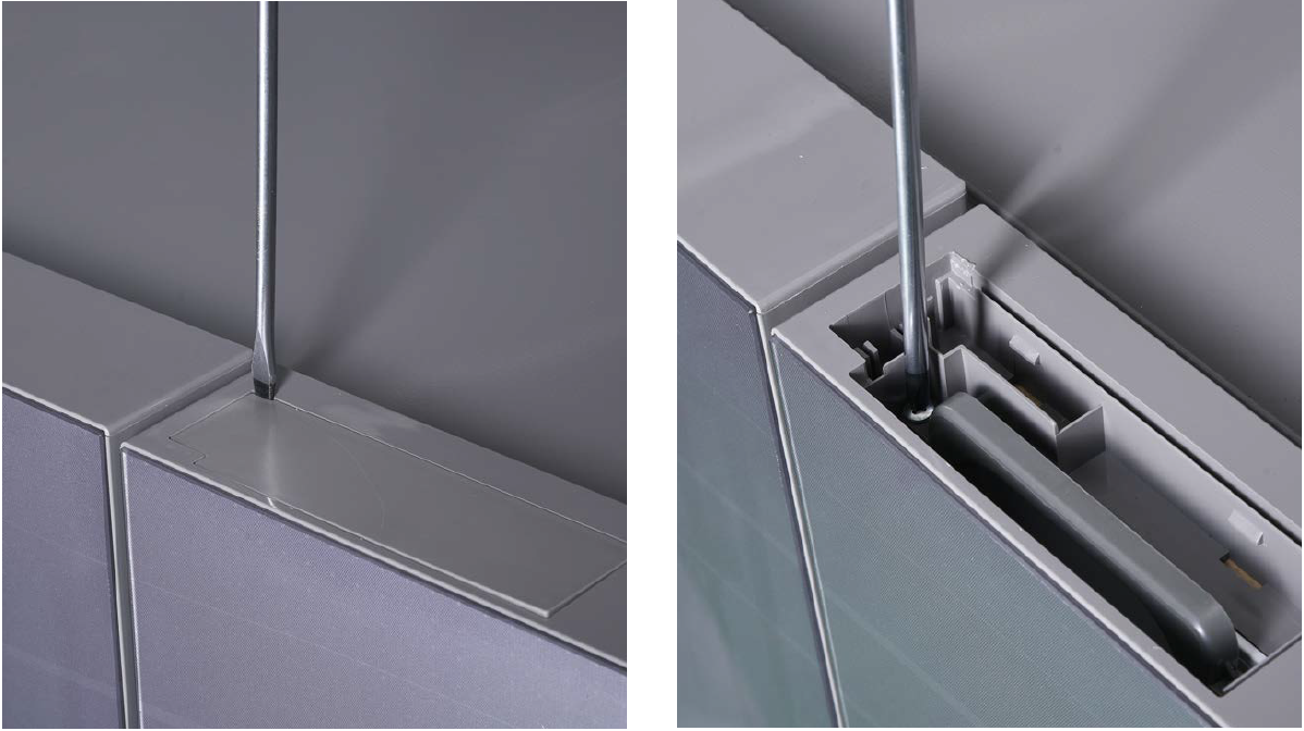
Step 3
Pull out the plastic.
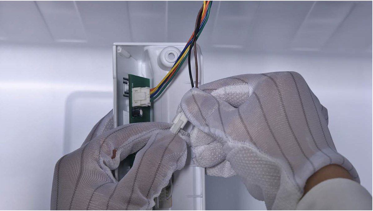
Step 4
Disconnect the terminal for display panel.
Step 5
Remove tape.
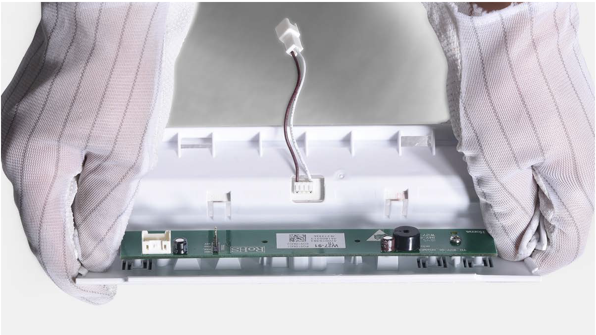
Step 6
Push the display away from the corner.
Reverse steps above
to install display
board.
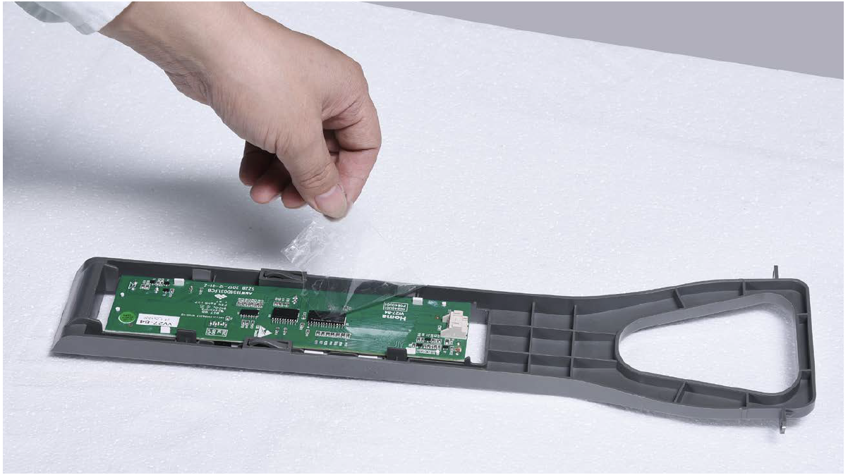
Follow tips carefully:
Tip 1
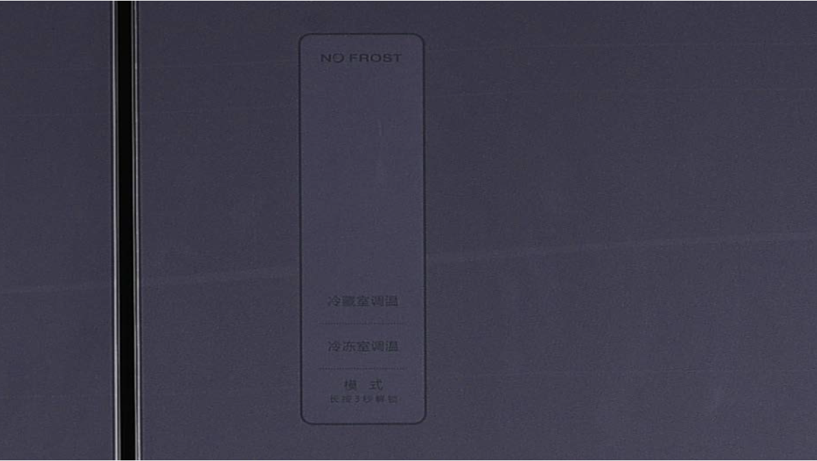
Please press all buttons on display board to check if it works well or not. Make sure words and icons are clear.
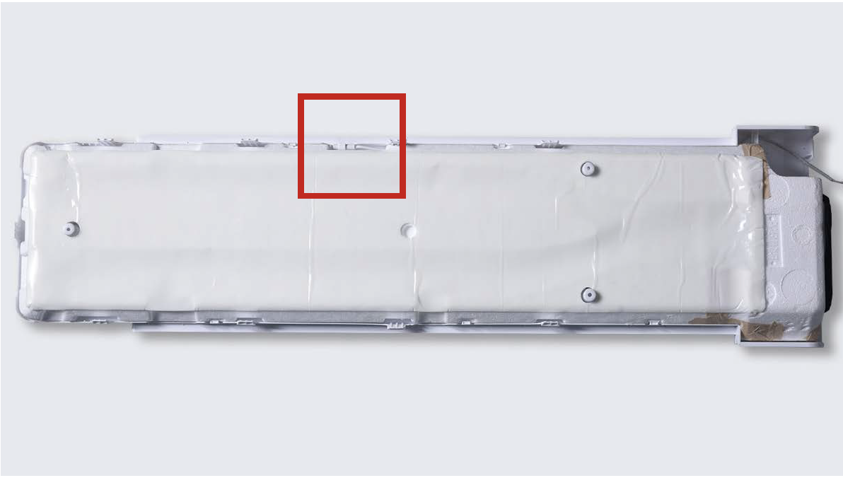
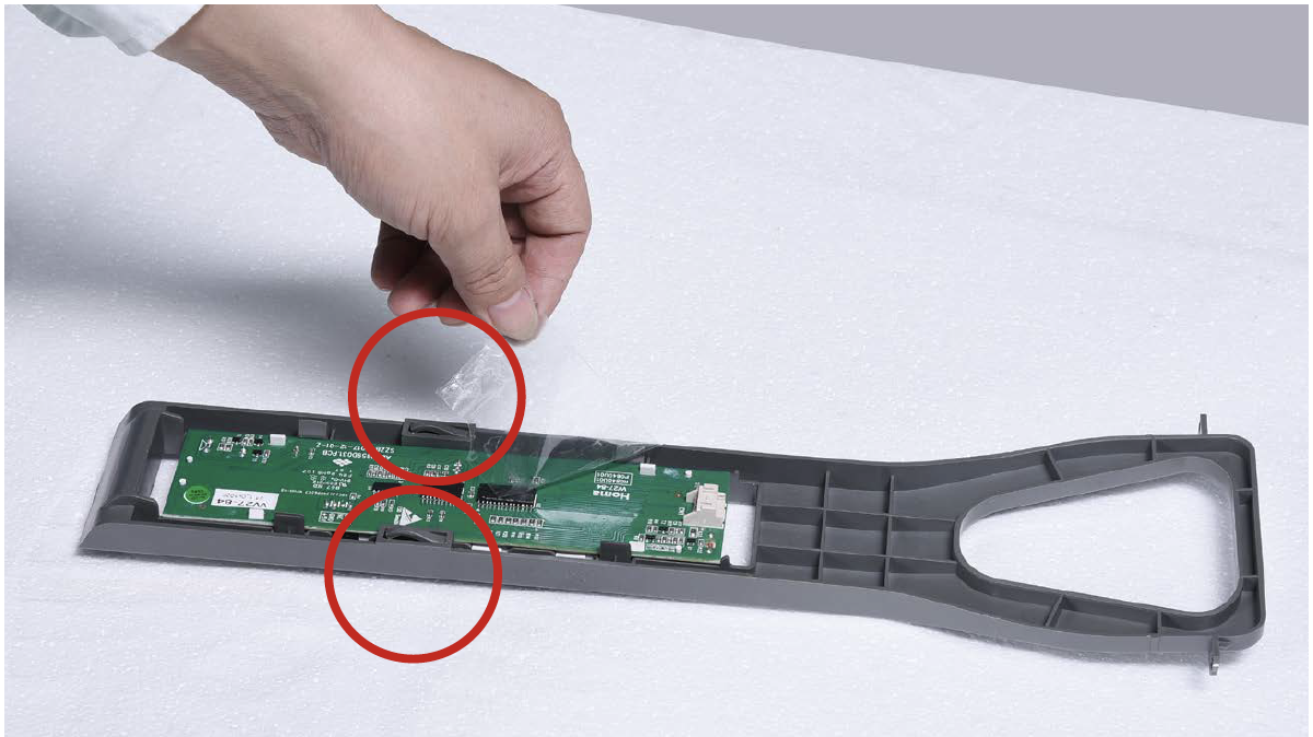
Tip 2
If not, disassemble it and put tape onto the point indicated by red circle.
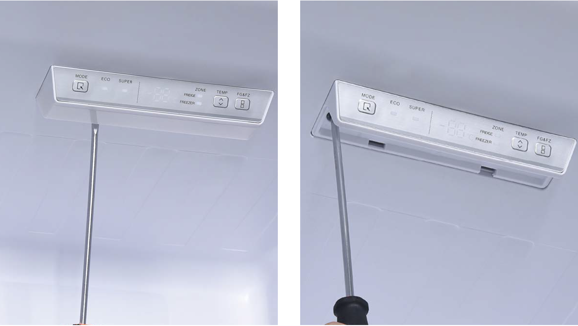
PROCEDURE 6
Step 1
Prize off the cover with slotted driver from back of cover.
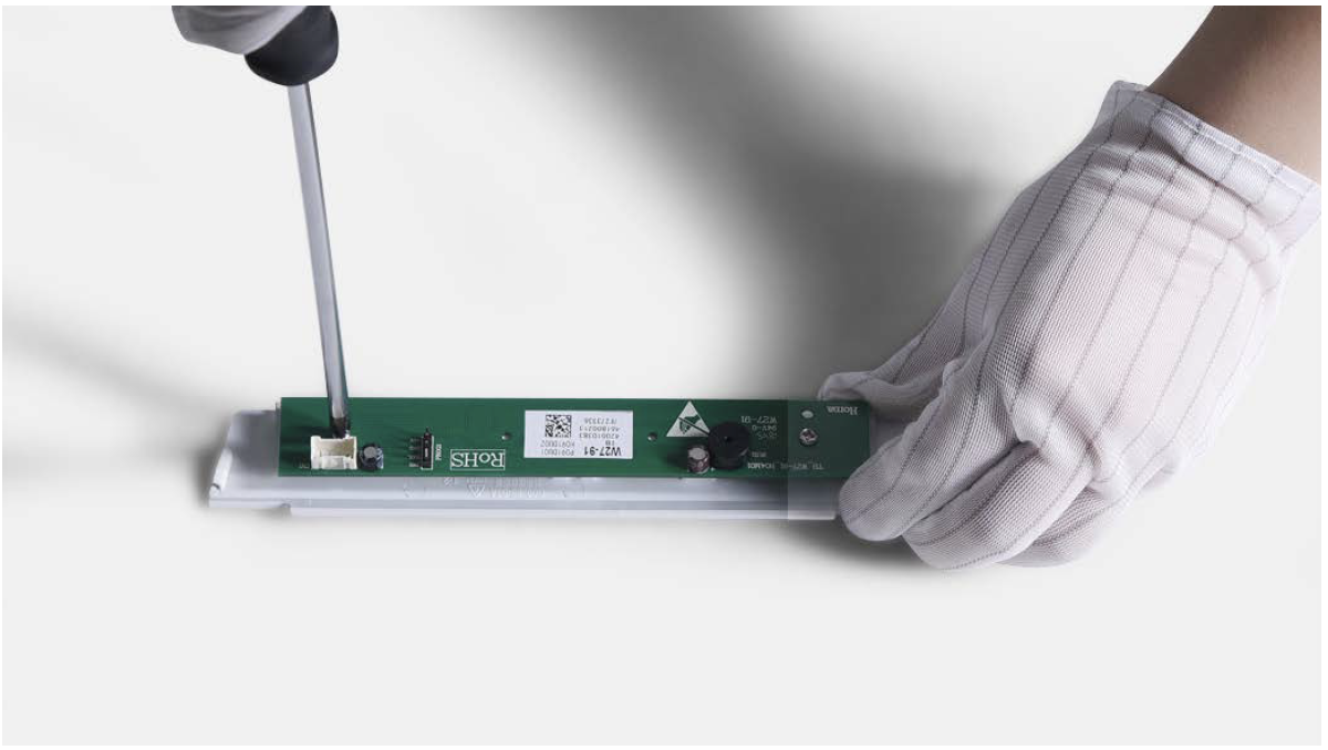
Step 2
Unscrew with 6mm Cross-head screwdriver.
Step 3
Pull down the lamp box.
Step 4
Disconnect the terminals for LED and for control board.
Step 5
Loosen the clips and take off the control panel.
Step 6
Unscrew with 6mm Philips screwdriver and move away the control board.
Reverse steps above to install the controll board. Please note below point:
Tip 1
Pay attention to wires while installing the internal display, to avoid damaging with screw.
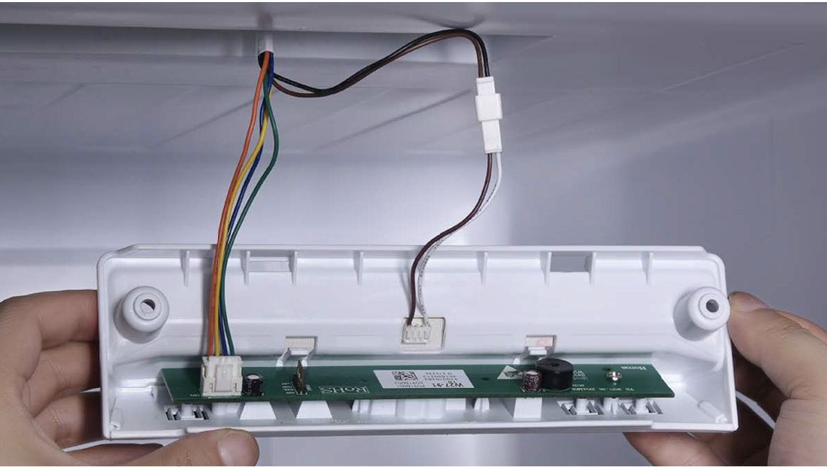
PROCEDURE 7
GENERAL PROCEDURES FOR DISASSEMBLY AND INSTALLATION OF MAINBOARD
Step 1
Prize up the terminal
clicks (if any).
Step 2
Disconnect the terminals.
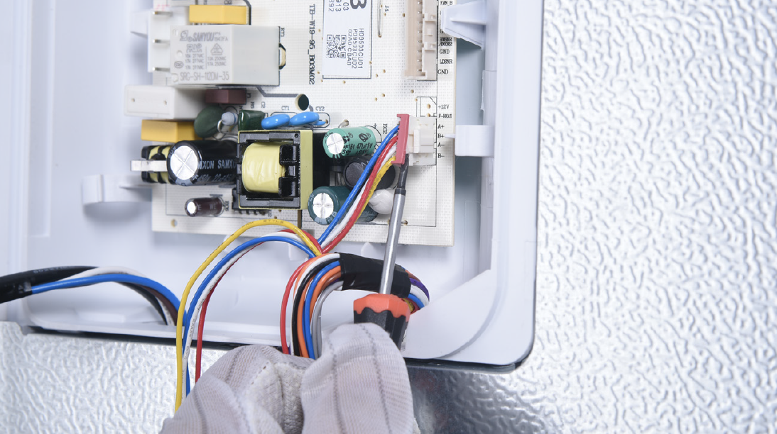
Step 3
Unscrew the mainboard.
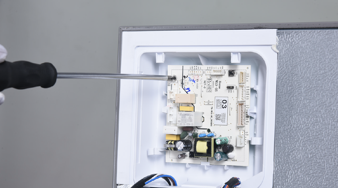
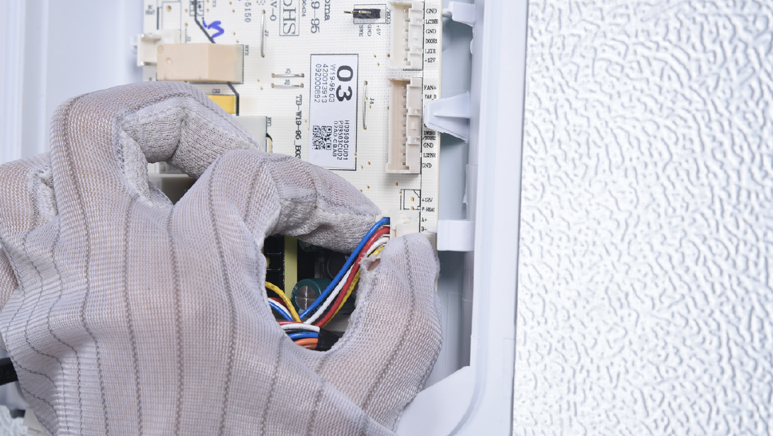
Step 4
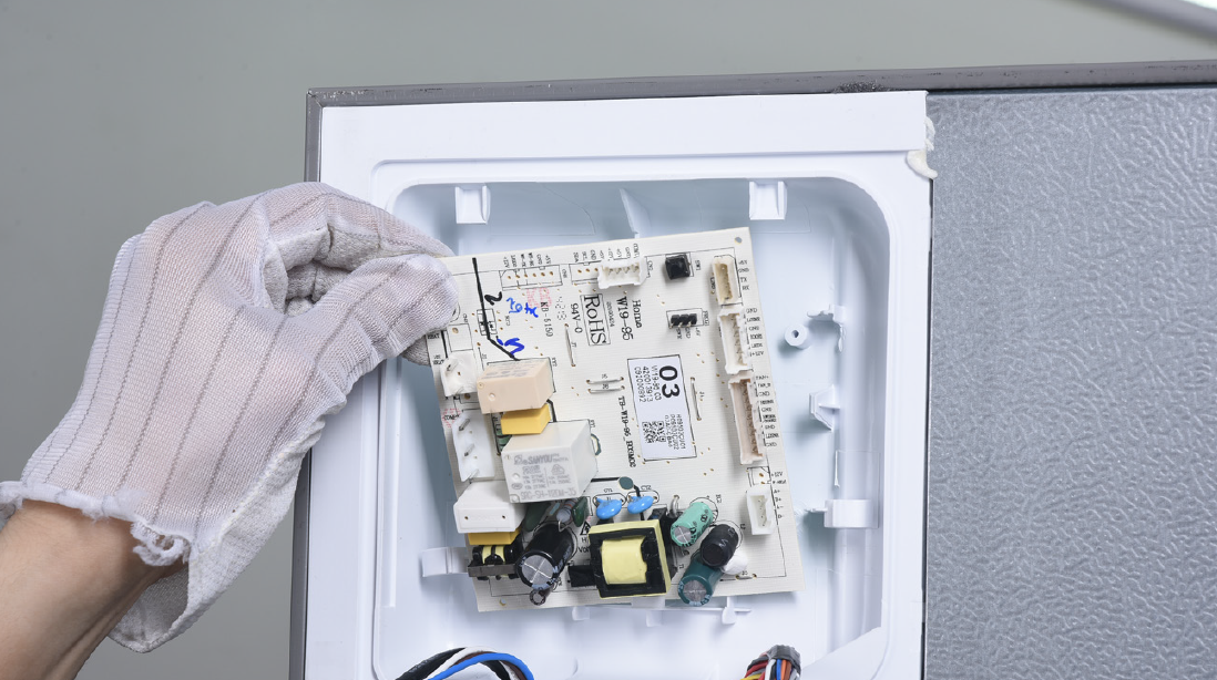
Prize off the buckle to remove mainboard.
Reverse steps above to install a new mainboard.
DIAGNOSIS 6


GO BACK TO COMPONENT LIST