

CHECK AND TEST 1
Step 1
Unscrew cover of mainboard with a cross-head screwdriver.

Step 2
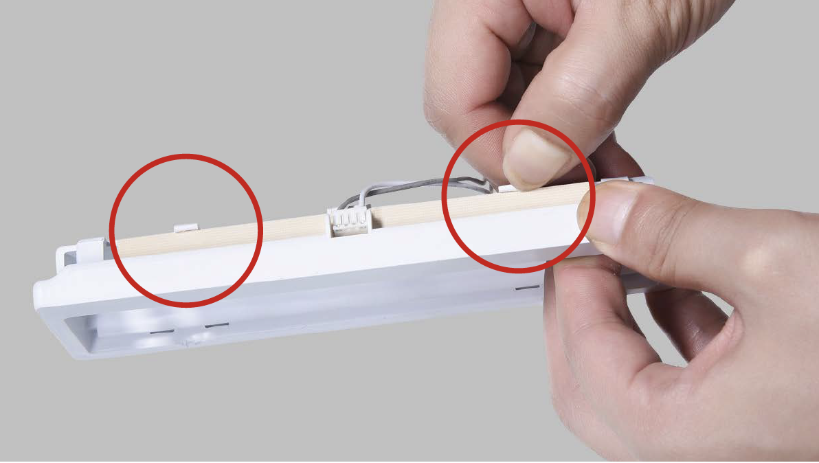
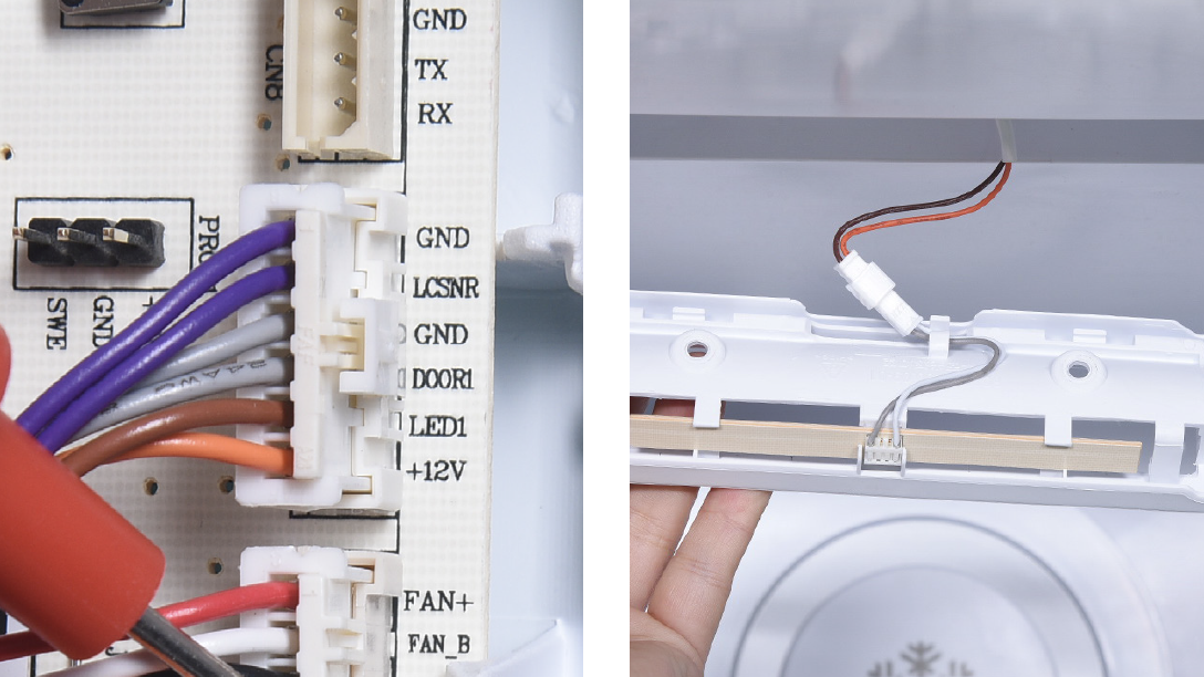
Check if terminal is inserted to final position in PCB area.

Step 3
Check if wire order for +
LED is right or not in PCB area.
Right picture shows the
correct condition.


DIAGNOSIS 1
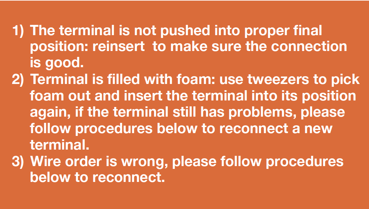
GENERAL PROCEDURES FOR RECONNECTING INTERNAL WIRES.
Step 1
Cut wire off.
Step 2
Peel off the sleeves.

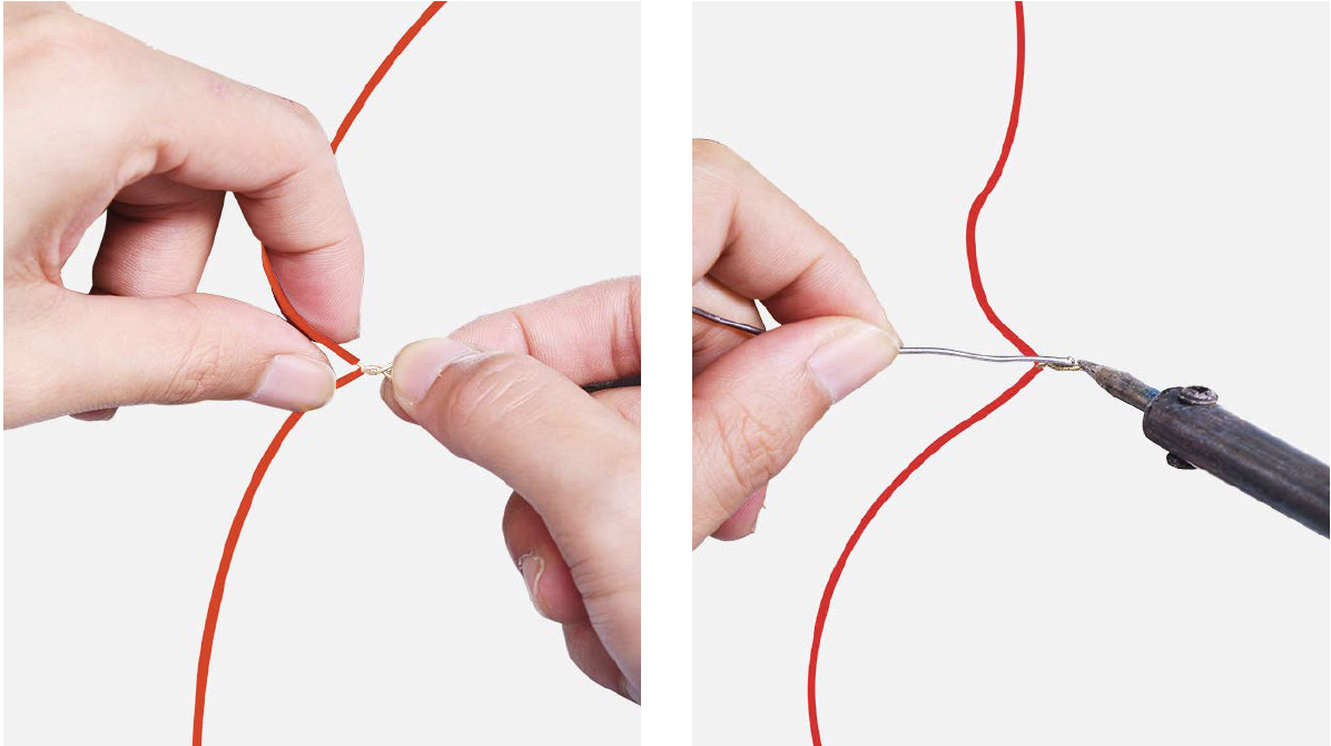
Step 3
Check to ensure proper wire order and reconnect them.
Step 4
Tin soldering.
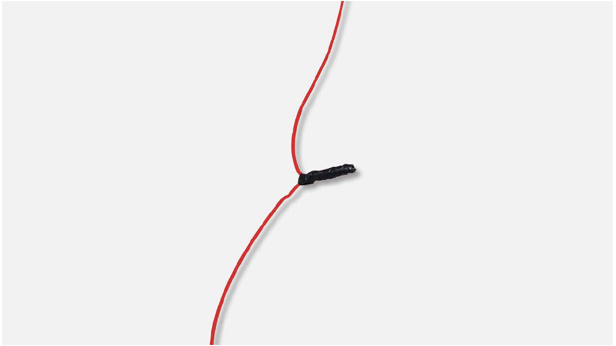
Step 5
Cover connecting point with electrical tape.
CHECK AND TEST 2
Step 1
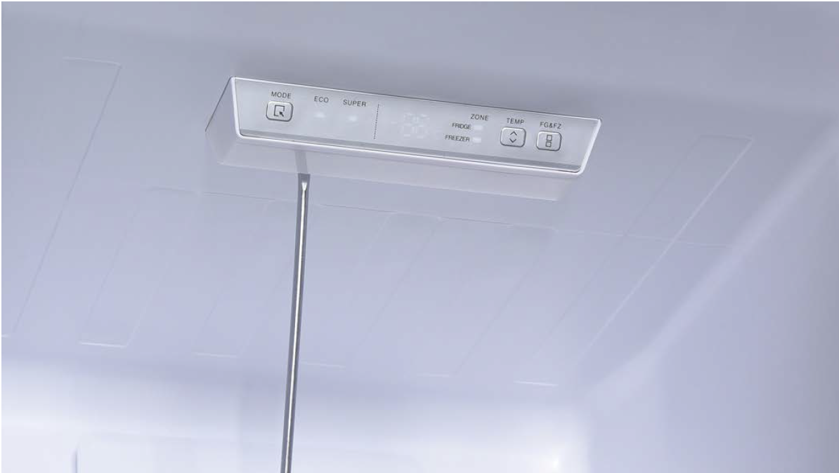
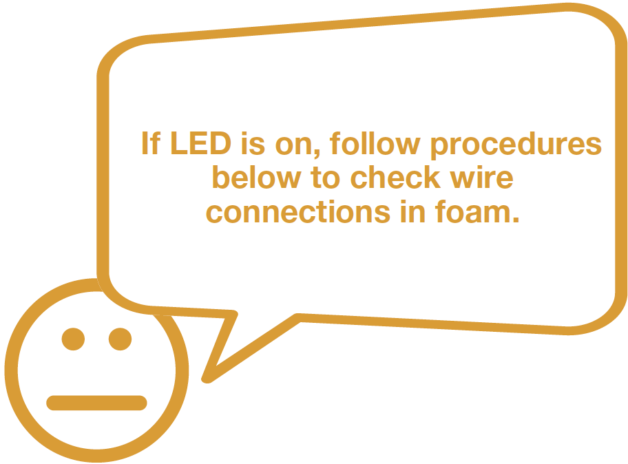
Power on the appliance, open fridge door, check if LED light is on or not.
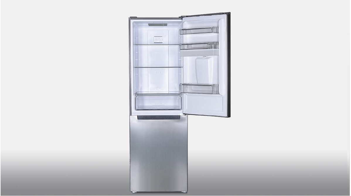
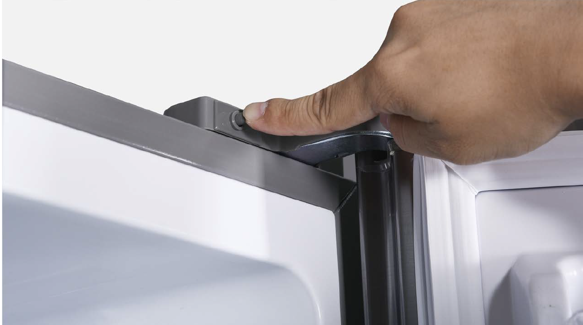
Step 2
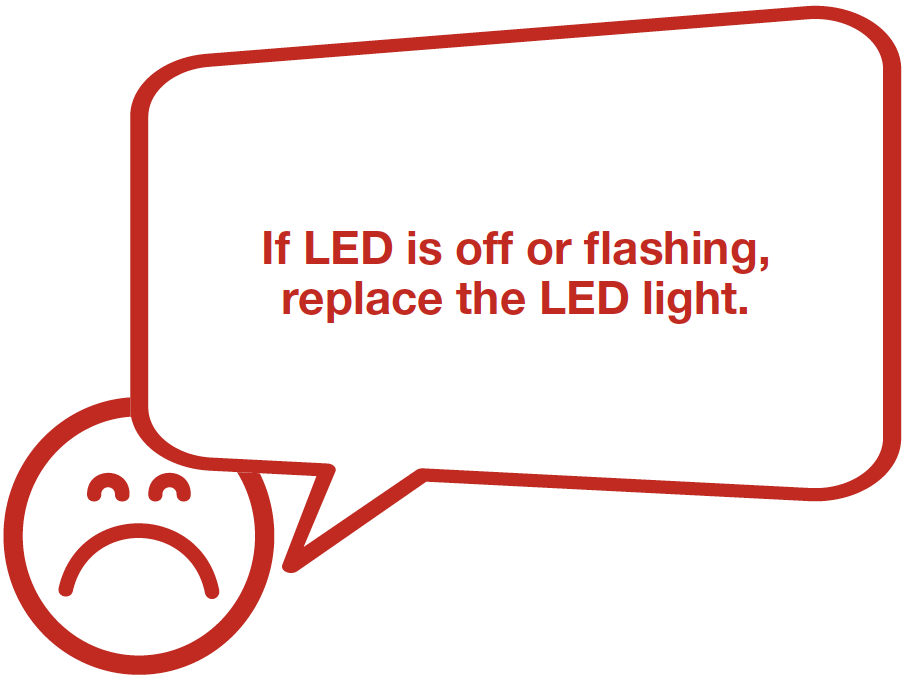
Press down the mechanical switch, check if LED light is off or not.
DIAGNOSIS 2


PROCEDURE 1
CASE 1:
LED LIGHT WITHOUT
CONTROL BOARD
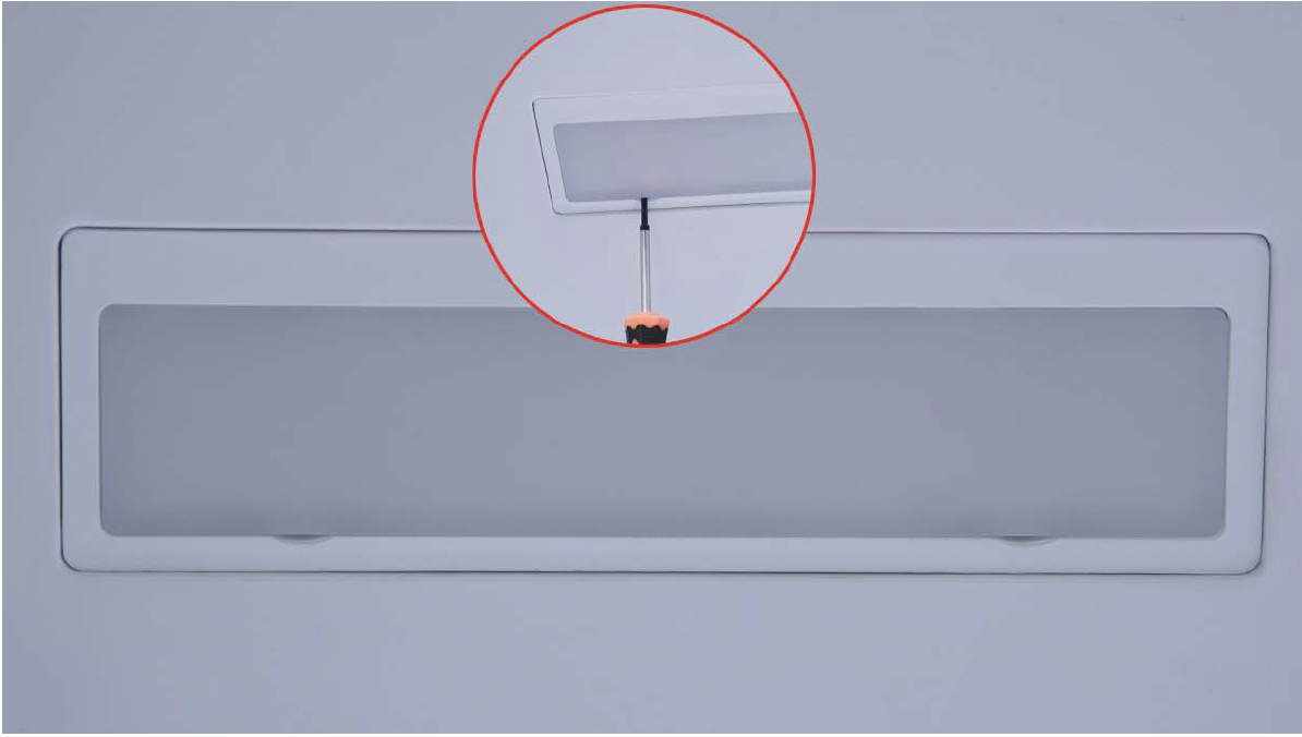
Step 1
Prize off the cover with 2mm slotted driver.
Step 2
Unscrew with 6mm Philips screwdriver.

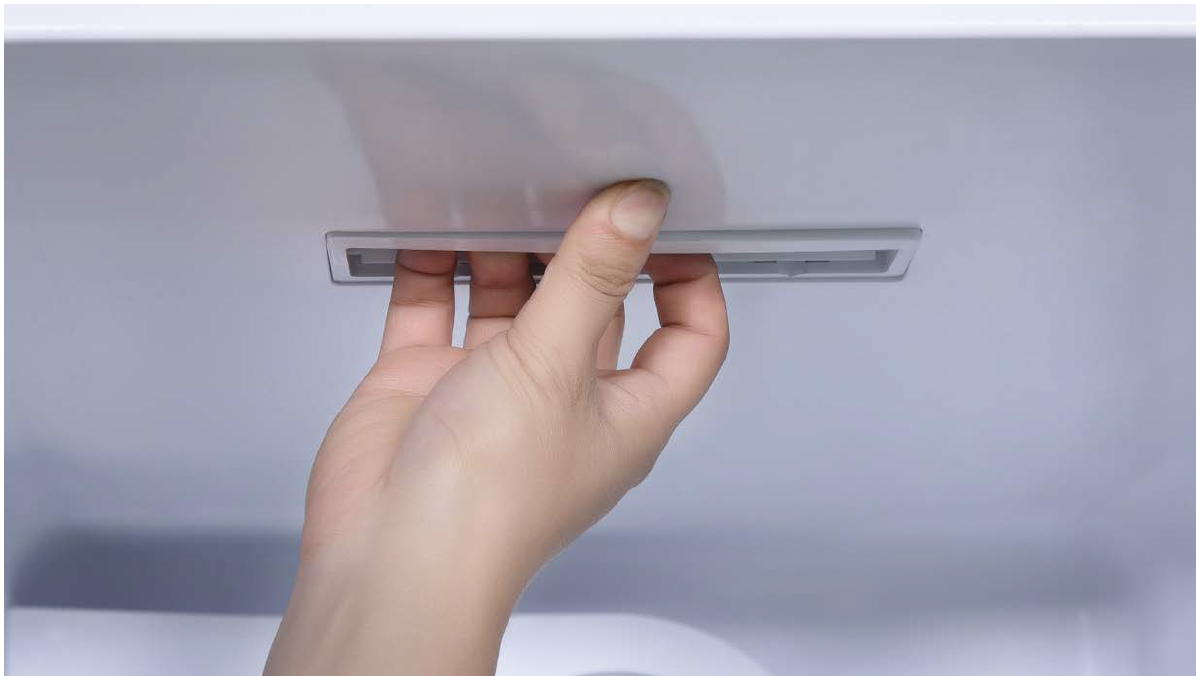
Step 3
Pull down the lamp box.
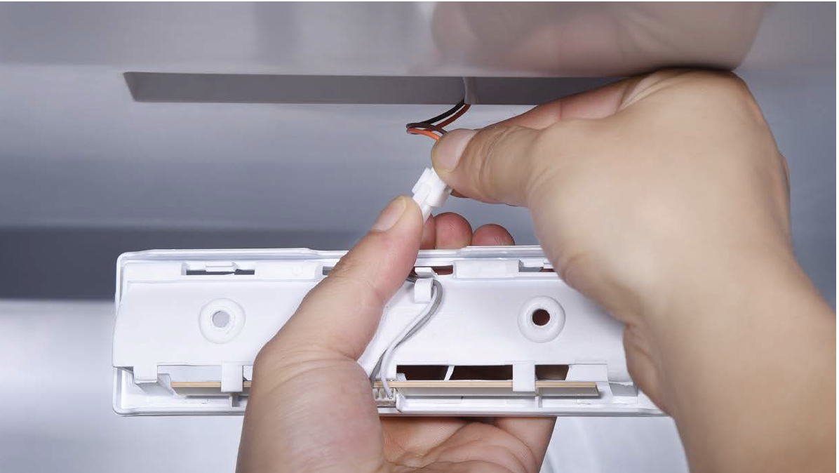
Step 4
Disconnect the terminal.
Step 5
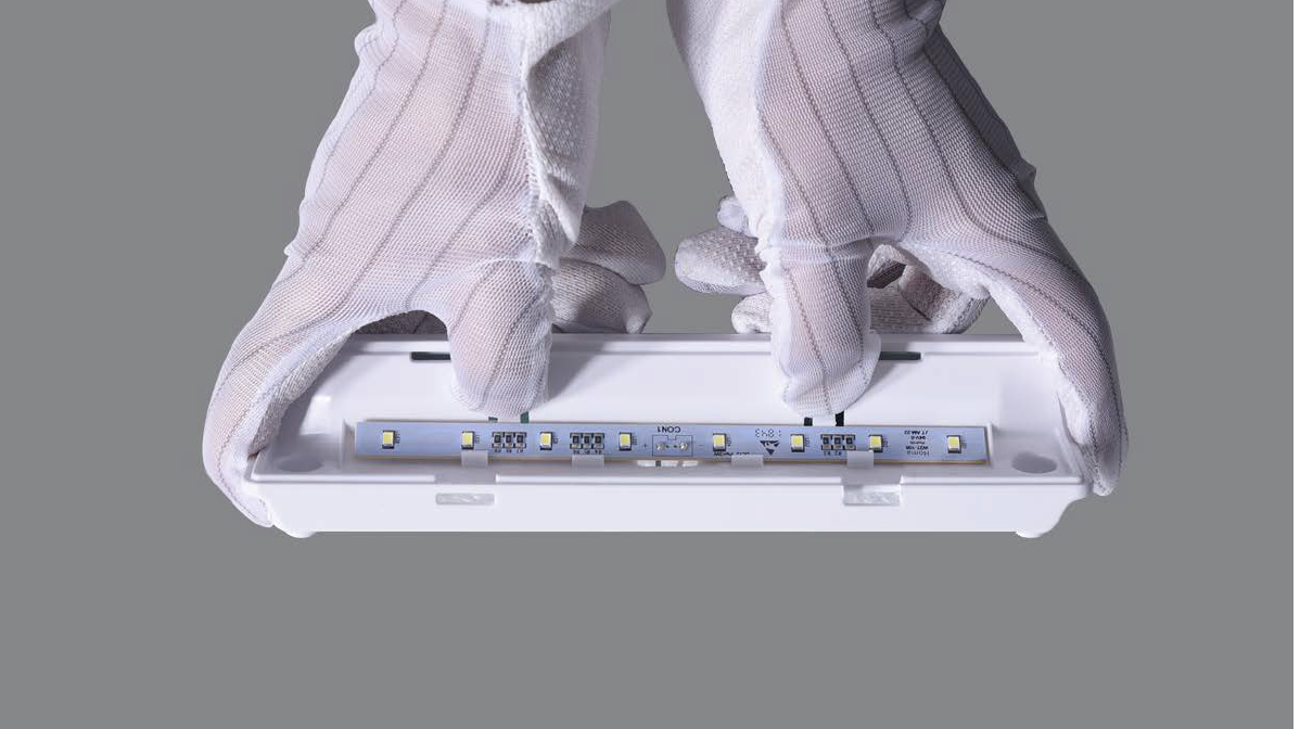
Loosen the clips and take off the LED lamp.
CASE 2:
LED LIGHT WITH INTERNAL
CONTROLLER
Step 1
Use slotted driver to prize off cover from back.
Step 2
Unscrew with 6mm Cross-head screwdriver.

Step 3
Pull down the lamp box.

Step 4
Disconnect the terminals for LED and for control board.

Step 5
Loosen the clips and take off the LED lamp.
CHECK AND TEST 3
Step 1
Provide DC12V to LED on the top to check if it is on or not.

DIAGNOSIS 3
CHECK AND TEST 4
Step 1
Set multimeter to resistance gear.

Step 2
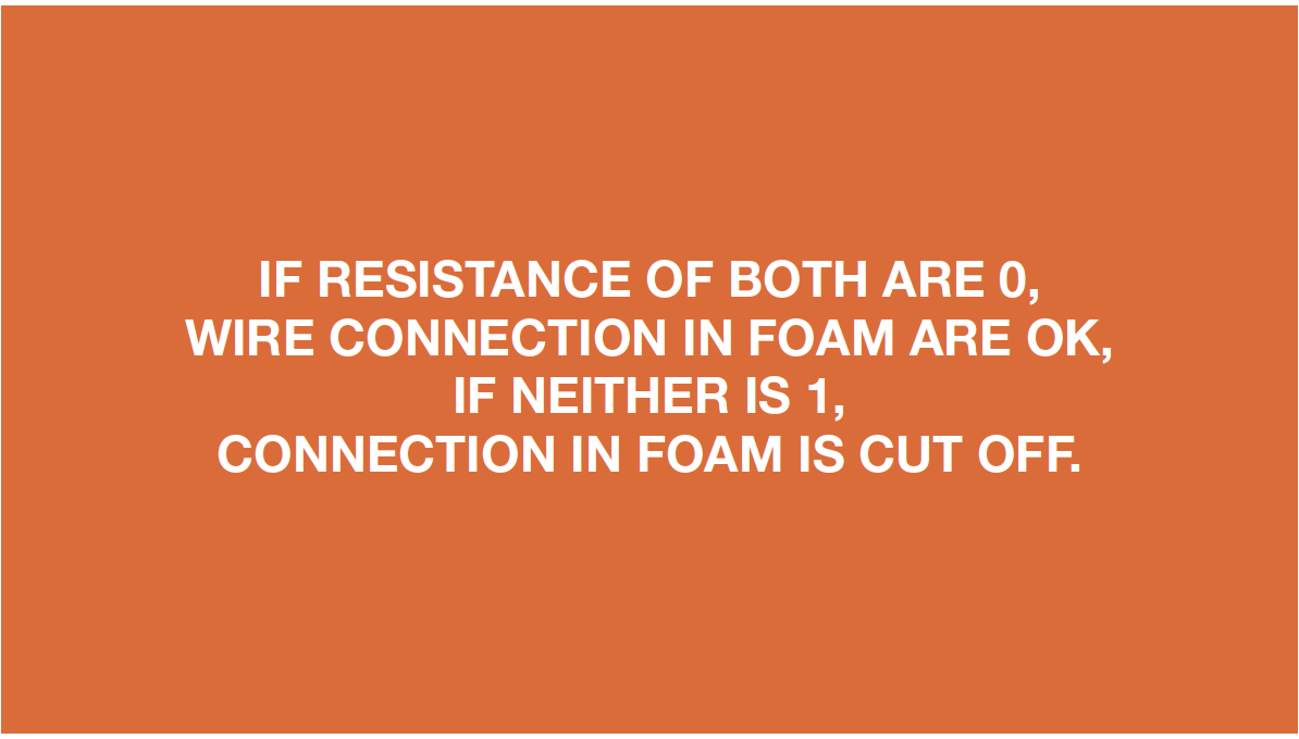
Check wire connection from PCB area to LED area.
CASE 1:
LED LIGHT WITHOUT
CONTROL BOARD
CASE 2:
LED LIGHT WITH INTERNAL
CONTROLLER

DIAGNOSIS 4

GO BACK TO COMPONENT LIST