

CHECK AND TEST 1
Step 1
Unscrew cover of mainboard with a Cross-head screwdriver.

Step 2
In PCB area, check if terminal is pushed into nal position.

Step 3
In PCB, check to see if
terminal is filled with foam.
Step 4 If so, use tweezers to
remove it.

Step 5
In PCB area, use multimeter to measure resistance value
.

Step 6
Take note of the result

Step 7
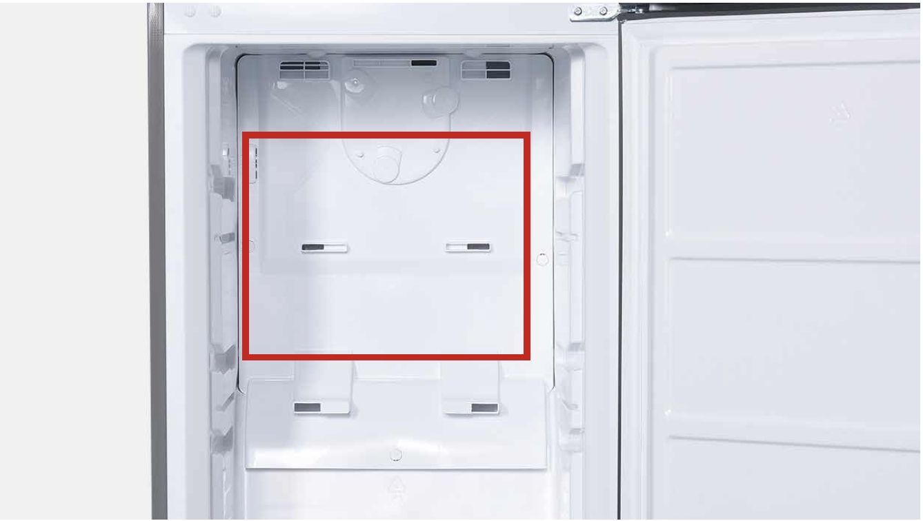
Measure the temperature of freezer air duct, close to sensor.

DIAGNOSIS 1


PROCEDURE 1

Step 1
Remove the drawers

Step 2
Remove the glass partition.

Step 3
Remove the 3 screw covers.

Step 4
Remove the 3 screws.
Step 5 Pull air duct out.

Step 6
Disconnect the terminal of fan motor.

Step 7
Remove the air duct.

CHECK AND TEST 2
Step 1
Check if terminal is
inserted to nal position.
If not, please re-insert it
to final position

Step 2
Check if sensor is fix to correct position, as showing in picture. If not, correct it.

Step 3
Check if wire of defrost
sensor is broken.
IF YES, REPLACE IT WITH A NEW ONE.

Step 4
Disconnect terminal of defrost temp. sensor.
Step 5 Check if the terminal is stuffed with foam.
If so, use tweezers to smash it and remove.

Step 6
Measure resistance of defrost temp. sensor
from terminal in freezer,
and take note of it.

Step 7 Measure the temperature of defrost temp. sensor.

DIAGNOSIS 2


PROCEDURE 2
Tip 1
When reassembling the air duct, move wires to
prevent crushing with edge of air duct.
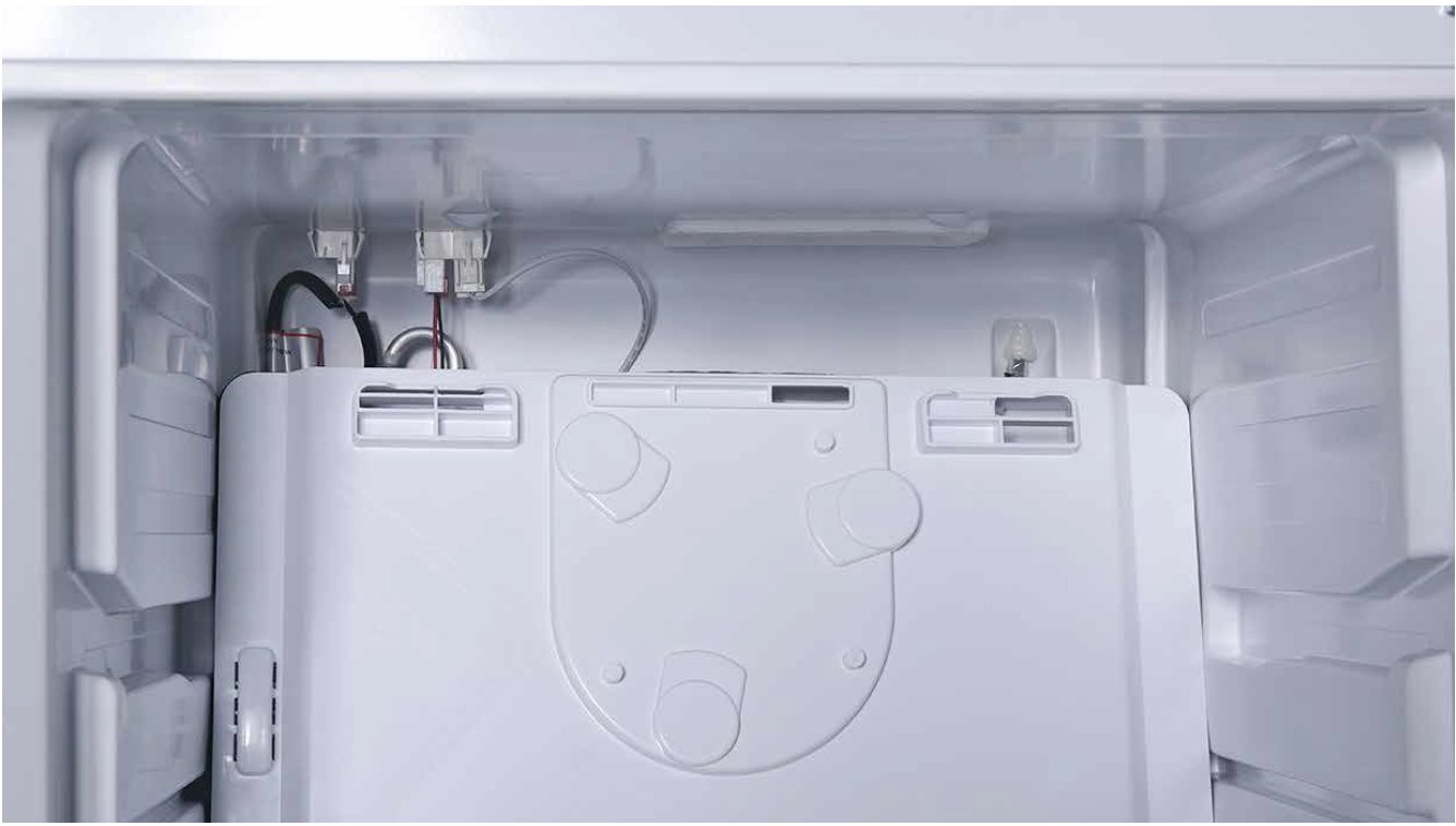
Tip 2 After pushing air duct into position, it should
make a click sound. If no click is heard, do it again.
Tip 3 Check to see if there is a large gap between air
duct and cabinet.
If there is, re-install air duct again.

DIAGNOSIS 3

CHECK AND TEST 3
Step 1
Set multimeter to resistance gear.
Step 2
Use a wire to connect the terminals in PCBarea and measure the resistance in foam side
(as shown in photo).

DIAGNOSIS


GO BACK TO COMPONENT LIST