


CHECK AND TEST 1
Step 1
Unscrew cover of mainboard with aCross-head screwdriver.

Step 2
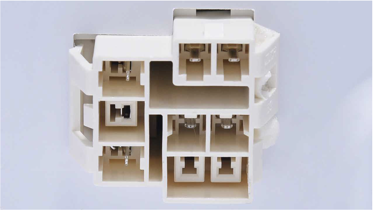
In PCB area, check if terminal is pushed intofinal position.

Step 3
Step 3In PCB, check to see if
terminal is filled with foam.
Step 4
If so, use tweezers toremove it.

Step 5
In PCB area, use multimeterto measure resistance value.

Step 6
Take note of the result.

Step 7
Measure the temperatureof freezer air duct, close to
sensor.

DIAGNOSIS 1


PROCEDURE 1
Step 1
Remove the drawers.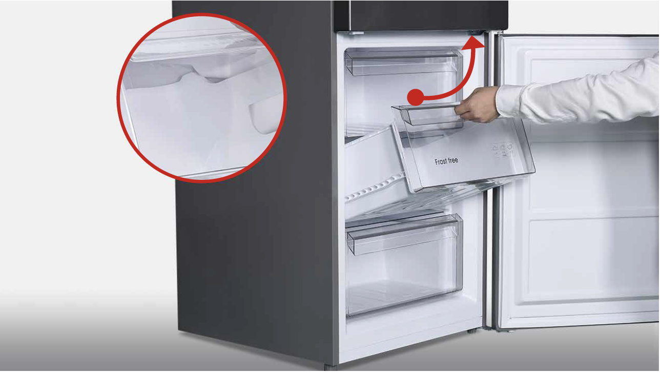
Step 2
Remove the glass partition.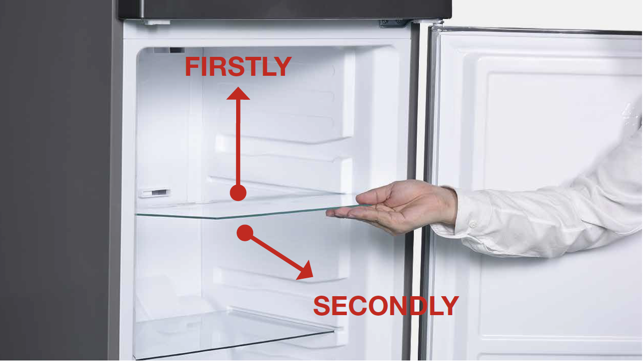
Step 3
Remove the 3 screwcovers.

Step 4
Remove the 3 screws.Step 5
Pull air duct out.

Step 6
Disconnect the terminal
of fan motor.

Step 7
Remove the air duct.
CHECK AND TEST 2
Step 1
Check if terminal is inserted to final position.
If not, please re-insert it to final position.

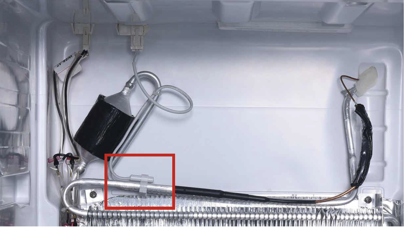
Step 2
Check if sensor is fix to correct position, asshowing in picture. If not, correct it.
Step 3
Check if wire of defrostsensor is broken.
IF YES, REPLACE IT
WITH A NEW ONE.

Step 4
Disconnect terminal ofdefrost temp. sensor.

Step 5
Check if the terminal is stuffed with foam.If so, use tweezers to smash it and remove.
Step 6
Measure resistance of defrost temp. sensorfrom terminal in freezer, and take note of it.

Step 7
Measure the temperatureof defrost temp. sensor.

DIAGNOSIS 2


PROCEDURE 2
Tip 1
When reassembling the air duct, move wires to prevent crushing with
edge of air duct.

Tip 2
After pushing air duct
into position, it should
make a click sound. If no
click is heard, do it again.
Tip 3
Check to see if there is
a large gap between air
duct and cabinet.
If there is, re-install
air duct again.

DIAGNOSIS 3

CHECK AND TEST 3
Step 1
Set multimeter toresistance gear.

Step 2
Use a wire to connectthe terminals in PCB
area and measure the
resistance in foam side
(as shown in photo).

DIAGNOSIS 4


PROCEDURE 3

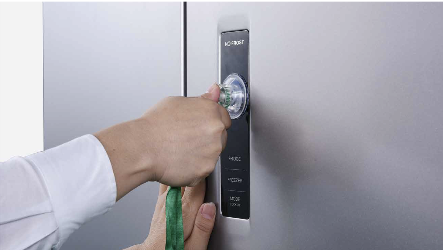
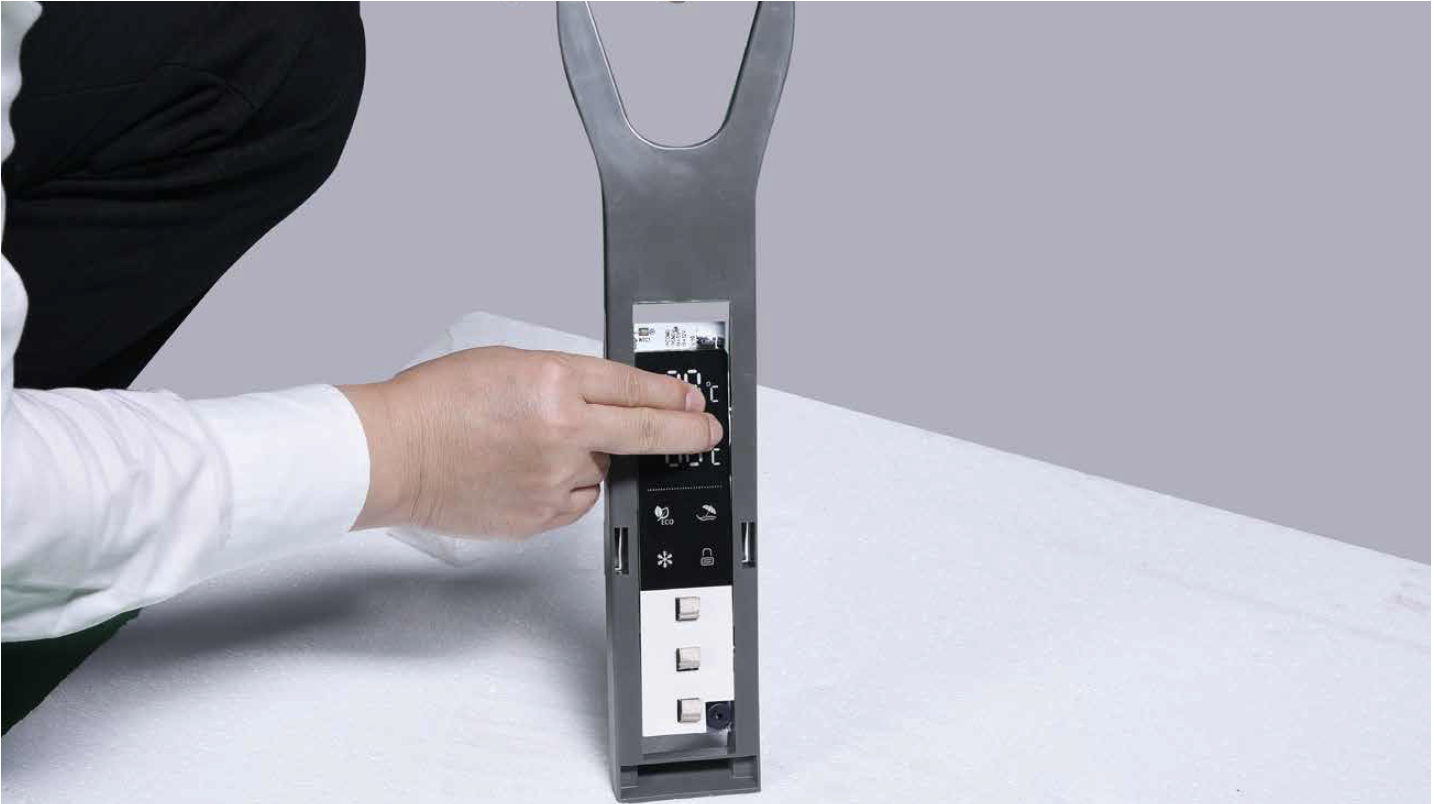
Step 1
Push a 6mm suckeronto display and turn
the knob to strengthen
suction force.

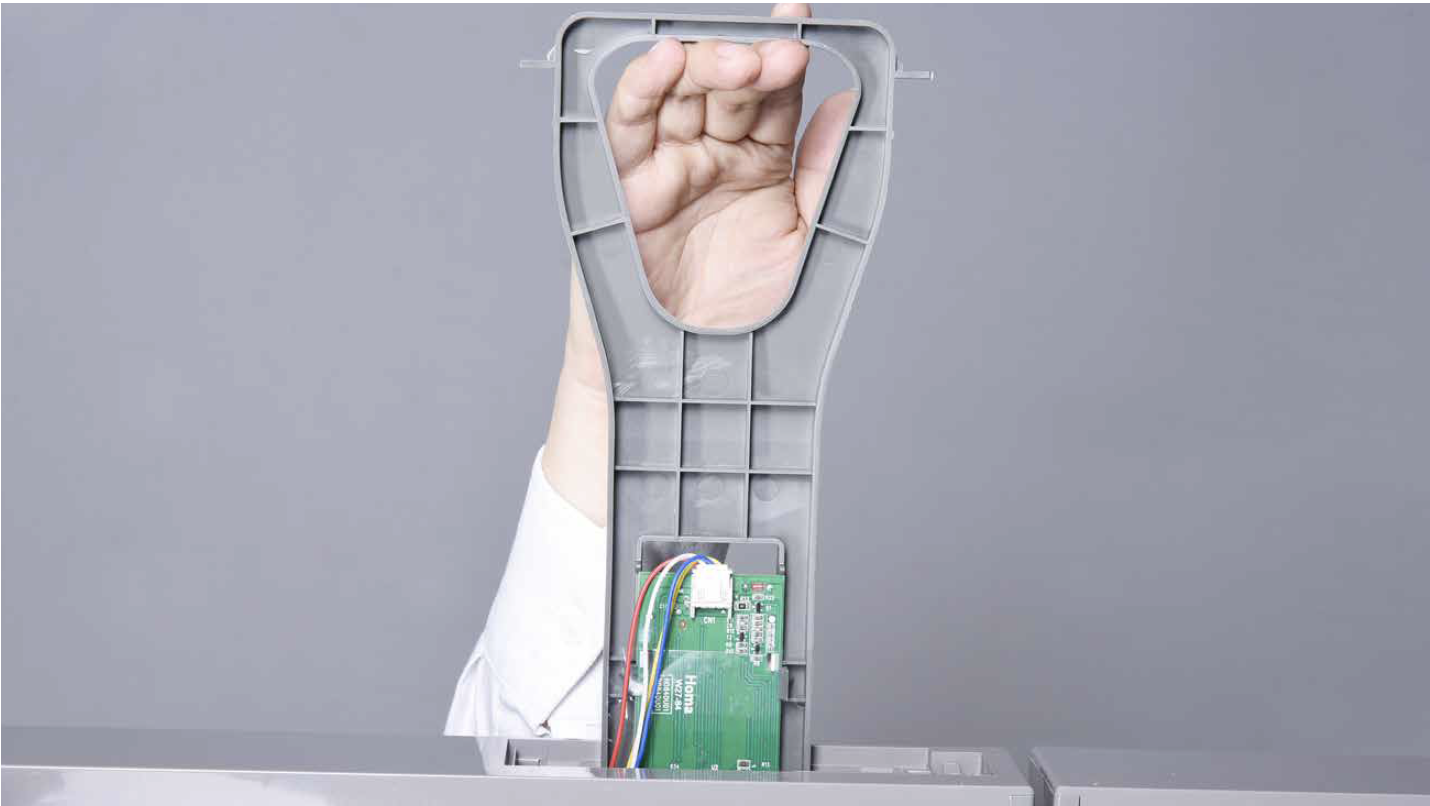
Step 2
Wrap a belt around knobto make it easier to pull
out of display board.
Tips for installing
display.
Tip 1
After connecting
terminal, please use tape
to fasten wires to avoid
crushing with cover.

Tip 2
After putting display
into cavity, press edge
until you hear a clicking
sound, this means the
board is pushed into final
position.
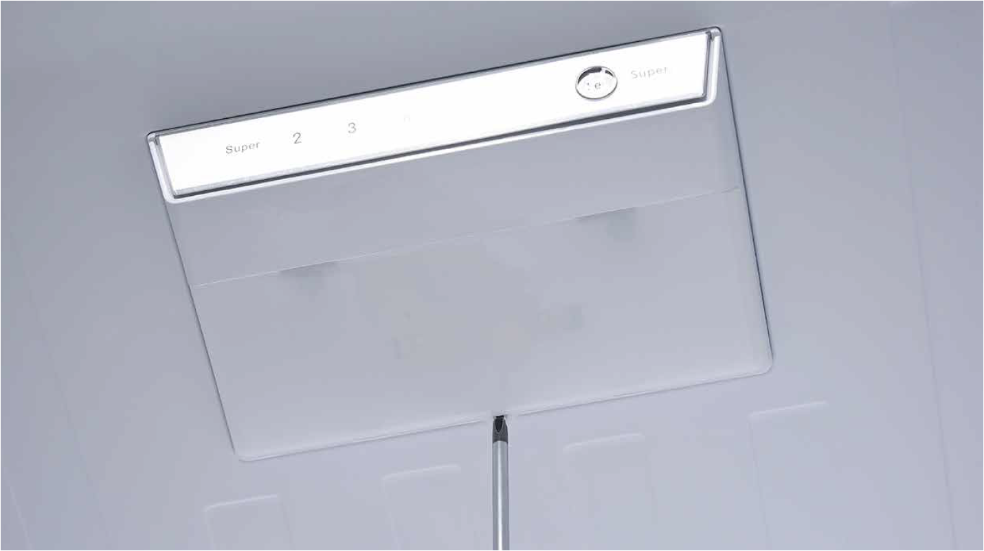
Tip 3
Please press all buttons
on display board to make
sure it works well.

PROCEDURE 4
Step 1
Prize off the cover ondoor cap.

Step 2
Remove the screws (intotal 2).

Step 3
Pull out the plastic;

Step 4
Disconnect the terminalfor display panel.
Step 5
Remove tape.
Step 6
Push the display awayfrom the corner.
:
Reverse steps above
to install display
board.
Follow tips carefully
Tip 1Please press all buttons
on display board to
check if it works well or
not. Make sure words
and icons are clear

Tip 2
If not, disassemble it and put tape onto the point indicated by red circle.

PROCEDURE 5

Step 1
Unscrew the screw oftop LED cover with 6mm
Cross-head screwdriver.
Step 2
Prize up the LED coverwith screwdriver.

Step 3
Remove the LED cover.
Step 4
Unscrew the screw of top LED bracketwith 6mm cross-head screwdriver.

Step 5
Disassemble the LEDbracket.

Step 6
Disconnect the control
PCB wire connector.

Step 7
Remove the controlPCB.
Reverse above steps to
install new control PCB.

PROCEDURE 6
Step 1
Unscrew cover ofmainboard with a
Cross-head screwdriver.

Step 2
Disconnect terminals.
Step 3
Unscrew the mainboard.
Step 4
Prize off the buckle toremove mainboard.

Step 5
Remove the mainboard.
Reverse above steps
to install a new board.

DIAGNOSIS 5


GO BACK TO COMPONENT LIST