


CHECK AND TEST 1
Step 1
Unscrew cover of mainboard with aCross-head screwdriver.

Step 2
Check if the terminal is filled with foam or not,then test resistance of fridge sensor from
terminal in PCB area.

Step 3
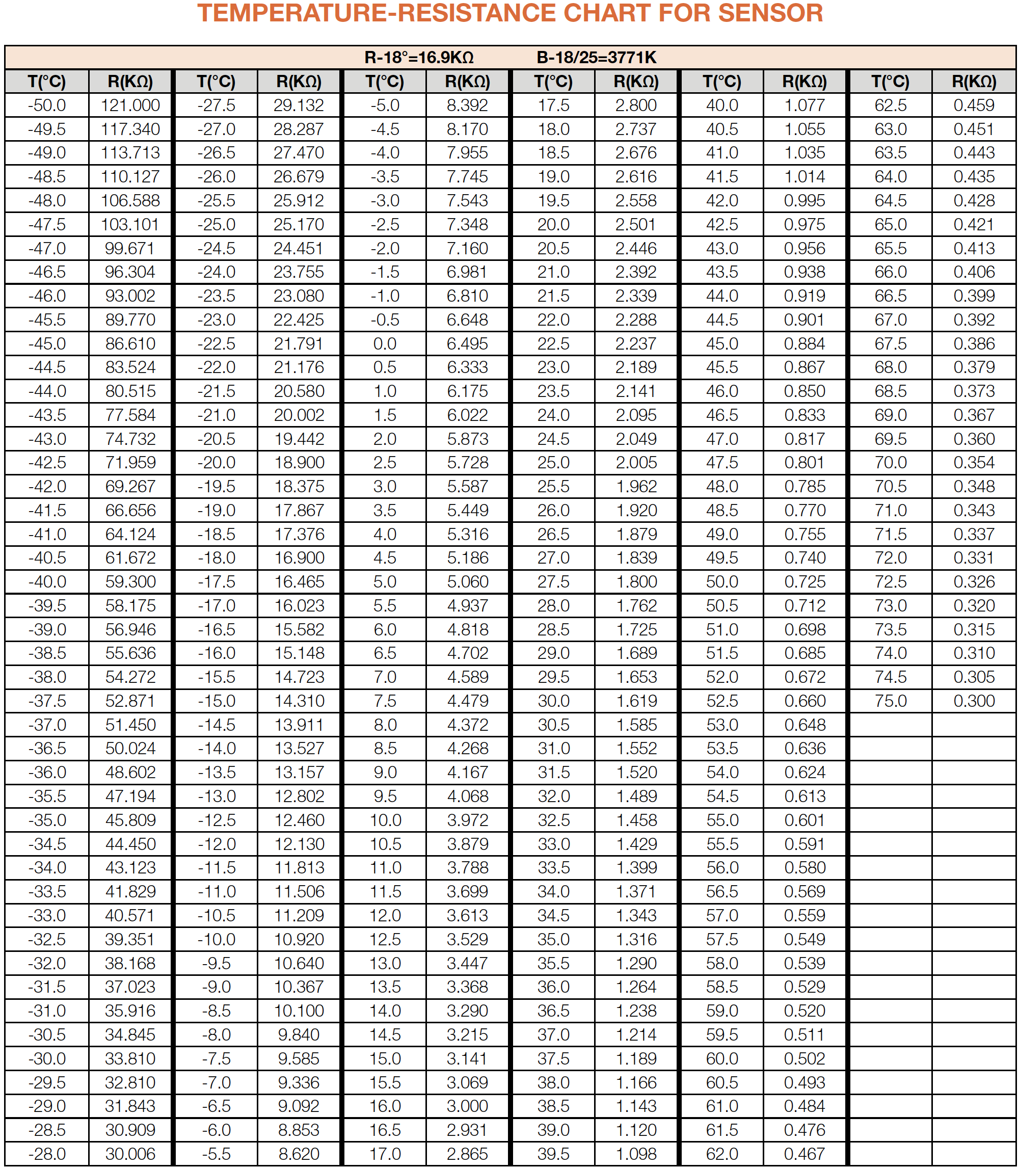
Take note of value.Step 4
Measure the temperature
of sensor.

DIAGNOSIS 1


PROCEDURE 1
Step 1
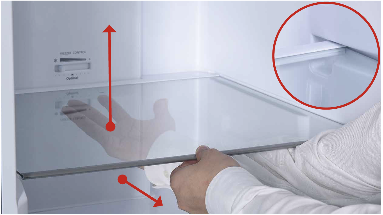
Remove shelves

Step 2
Remove crisper drawer.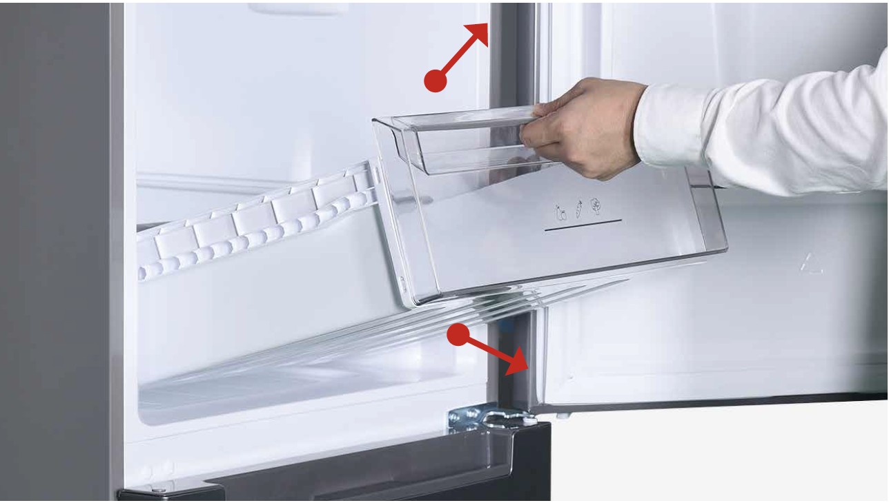
Step 3
Remove crisper drawercover shelf.
Step 4
Remove crisper drawercover shelf.
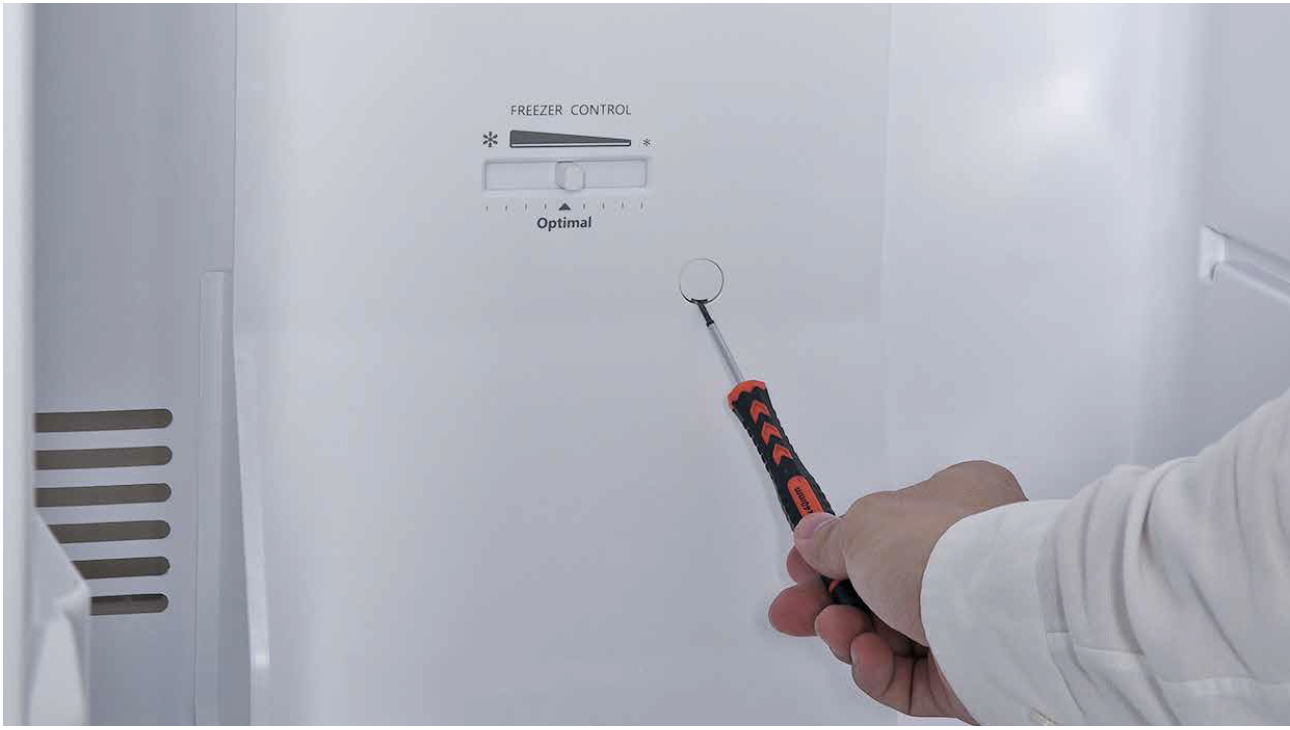
Step 5
Use screwdriver toleverage decorative panels from the bottom and remove
Step 6
Remove the 2 screws onfridge air duct.
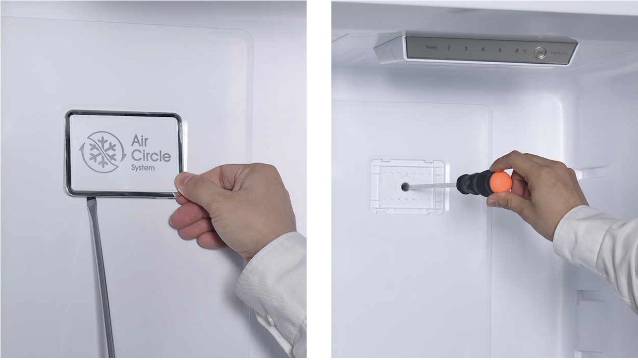
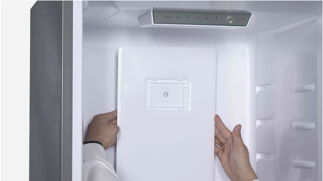
Step 7
Pull out the air duct.
Step 8
Disconnect the terminals.

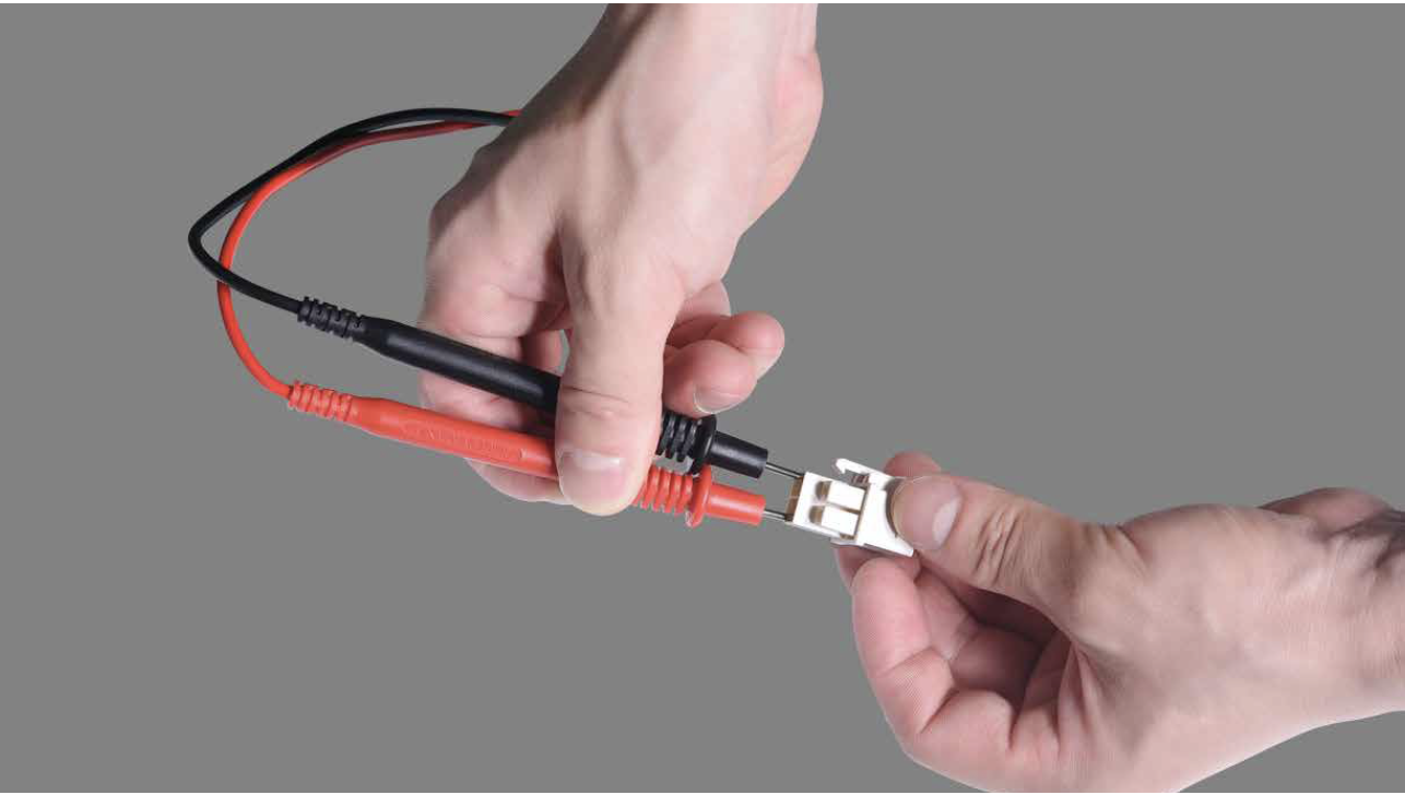
CHECK AND TEST 2
Step 1
Test resistance of sensorfrom terminal in duct
cover.
DIAGNOSIS 2

PROCEDURE 2
Step 1
Release the clasp.
Step 2
Remove the foam air duct.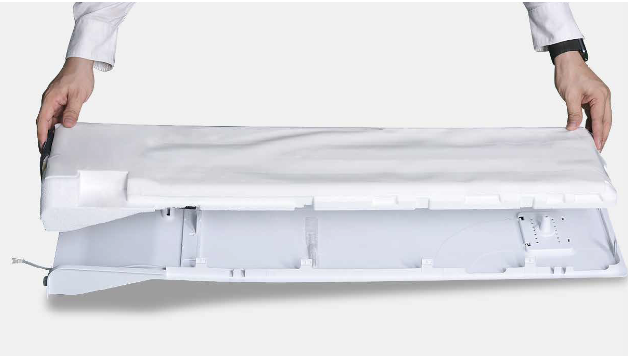
Step 3
Remove tape.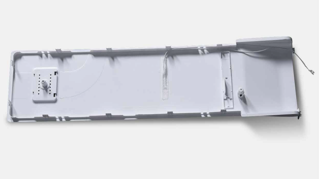
Step 4
Remove the brokensensor.
Reverse above
procedures to reinstall
temp. sensor and fridge
air duct.

CHECK AND TEST 3
Step 1
Set multimeter toresistance gear.

Step 2
Use a wire to connect 2pins of terminals in PCB
area, then measure the
connection.

DIAGNOSIS 3


PROCEDURE 3
DIAGNOSIS 5


PROCEDURE 4

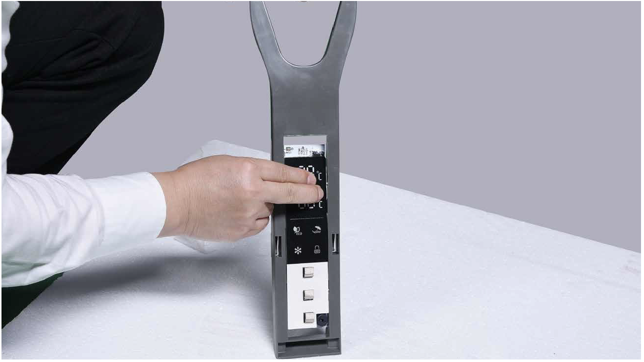
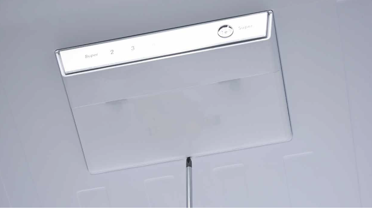
Step 1
Push a 6mm sucker onto display and turnthe knob to strengthen suction force.
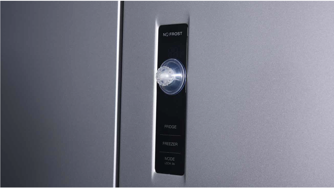
Step 2
Wrap a belt around knobto make it easier to pull
out of display board.

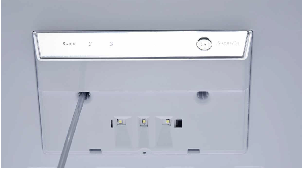
Tips for installing
display.
Tip 1
After connecting terminal, please use tape
to fasten wires to avoid crushing with cover.

Tip 2
After putting display into cavity, press edgeuntil you hear a clicking sound, this means the
board is pushed into final position.
Tip 3
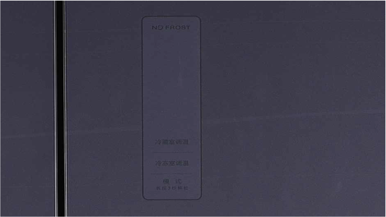
Please press all buttons
on display board to make
sure it works well.

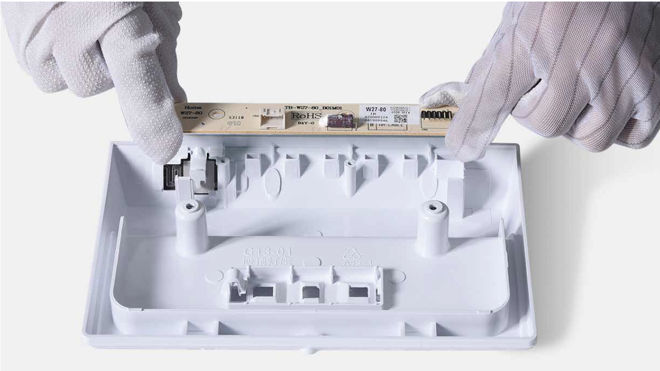
PROCEDURE 5

Step 1
Prize off the cover ondoor cap.
Step 2
Remove the screws (intotal 2).

Step 3
Pull out the plastic;
Step 4
Disconnect the terminalfor display panel.

Step 5
Remove tape.

Step 6
Push the display awayfrom the corner.
Reverse steps above
to install display
board.
Follow tips carefully:
Tip 1
Please press all buttons on display board tocheck if it works well or not. Make sure words
and icons are clear.
Tip 2
If not, disassemble it and put tape onto the point indicated by red circle.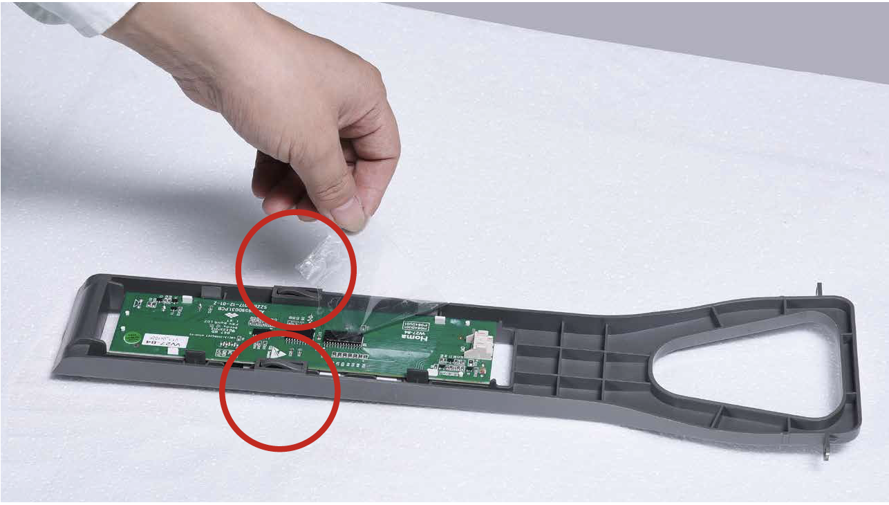

PROCEDURE 6
Step 1
Unscrew the screw of top LED cover with 6mmCross-head screwdriver.
Step 2
Prize up the LED coverwith screwdriver.

Step 3
Remove the LED cover.
Step 4
Unscrew the screw of top LED bracketwith 6mm cross-head screwdriver.
Step 5
Disassemble the LED
bracket.

Step 6
Disconnect the controlPCB wire connector.

Step 7
Remove the control PCB.Reverse above steps to
install new control PCB.
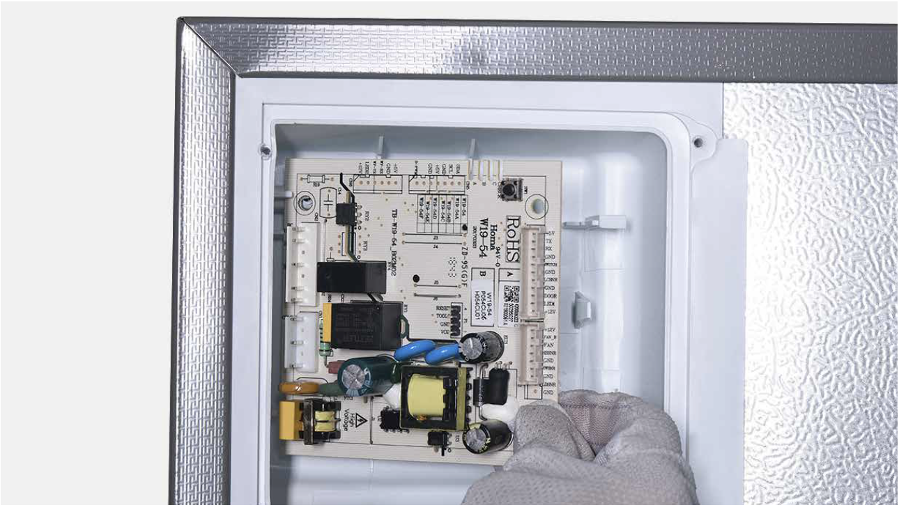
PROCEDURE 7
Step 1
Unscrew cover of mainboard with aCross-head screwdriver.

Step 2
Disconnect terminals.
Step 3
Unscrew the mainboard.
Step 4
Prize off the buckle to remove mainboard.
Step 5
Remove the mainboard.Reverse above steps
to install a new board.
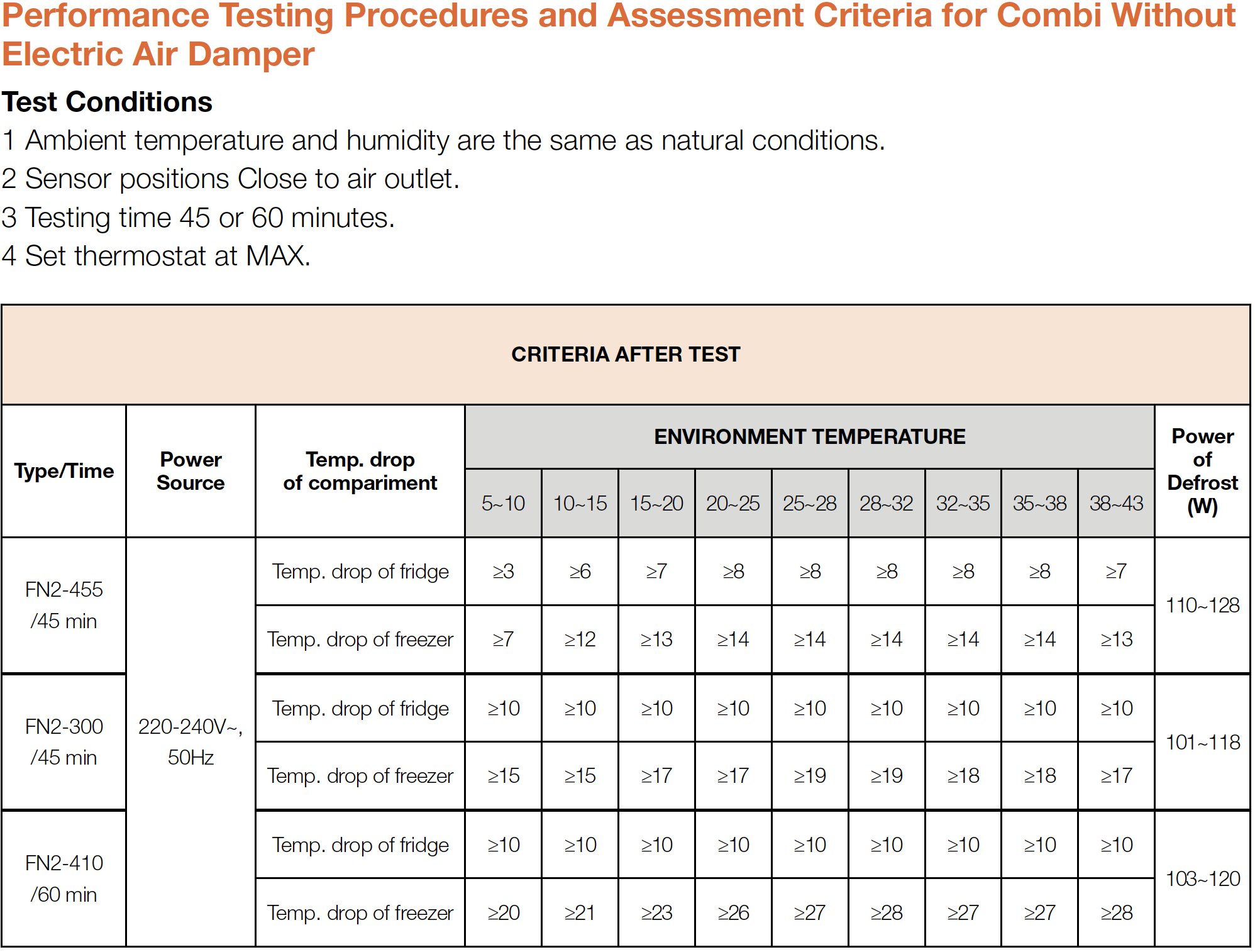
DIAGNOSIS 6

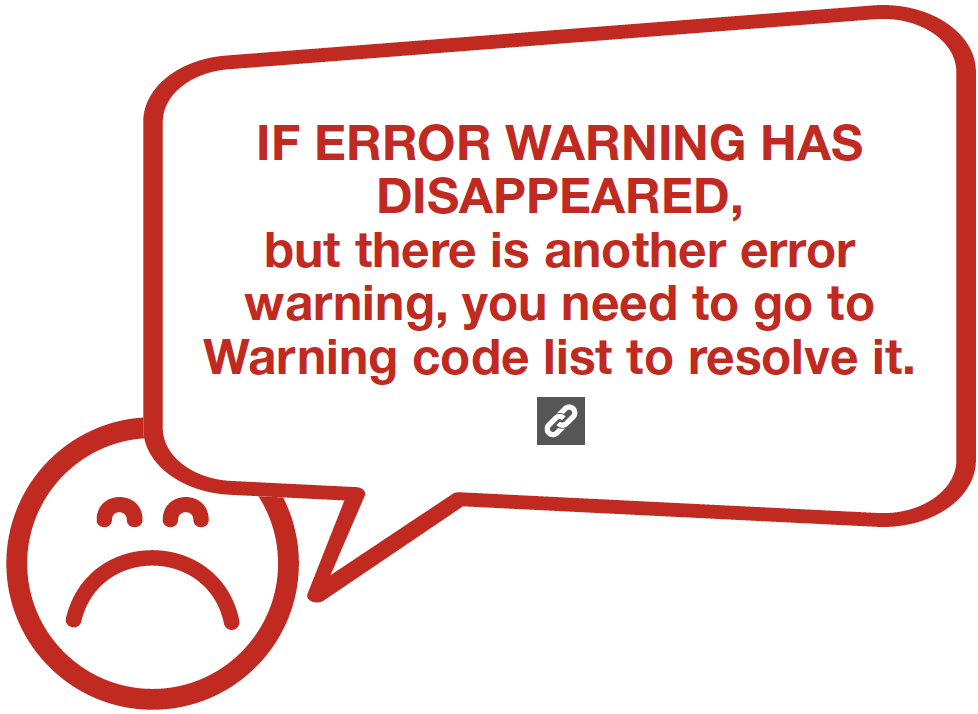

GO BACK TO ERROR CODE LIST