

CHECK AND TEST 1
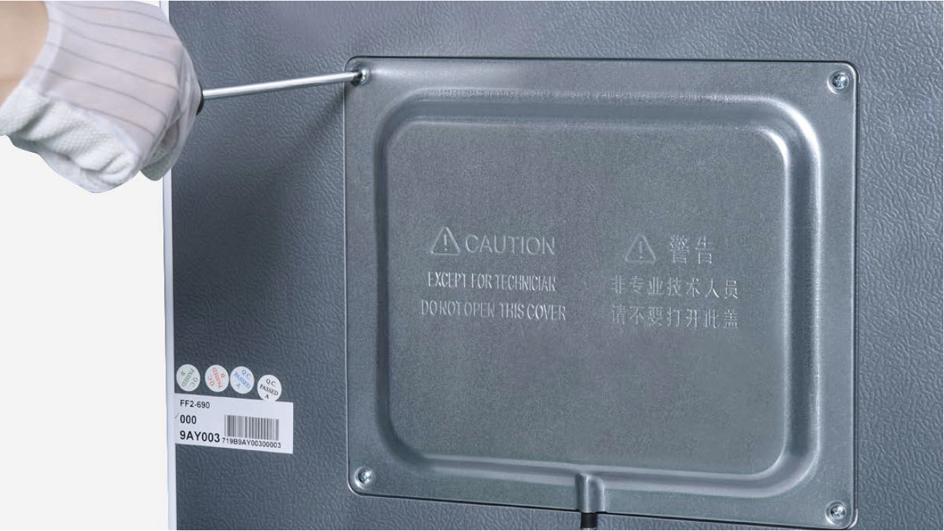
Step 1
Unscrew cover of mainboard with a Cross-head screwdriver.
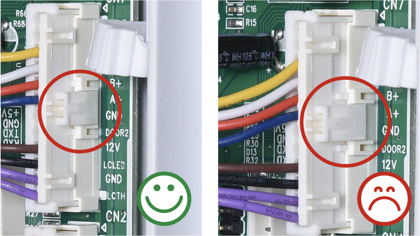
Step 2
In mainboard area, check if terminal is pushed into proper final position.
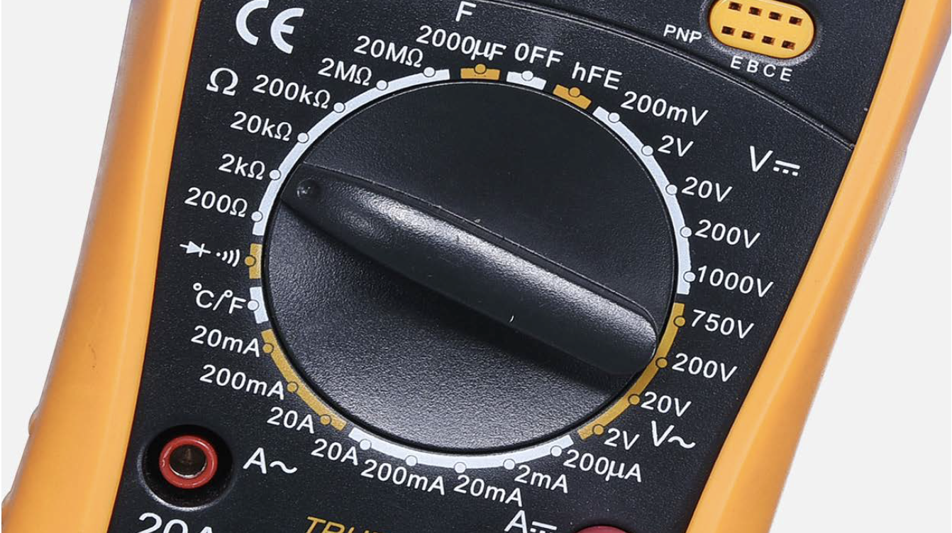
Step 3
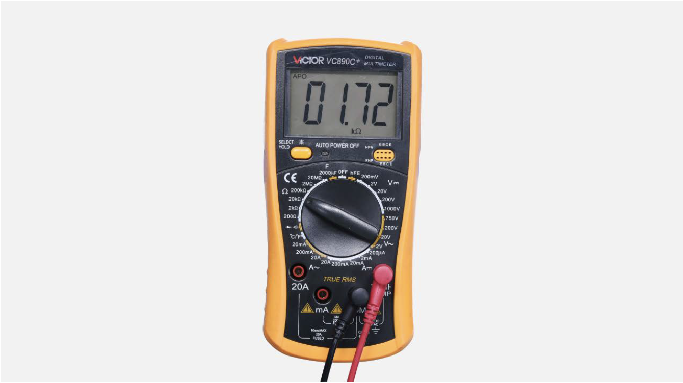
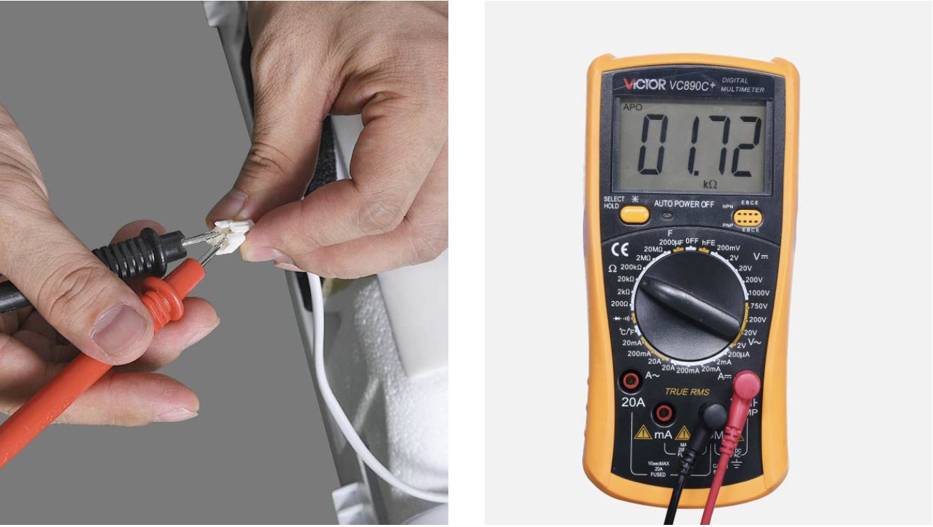
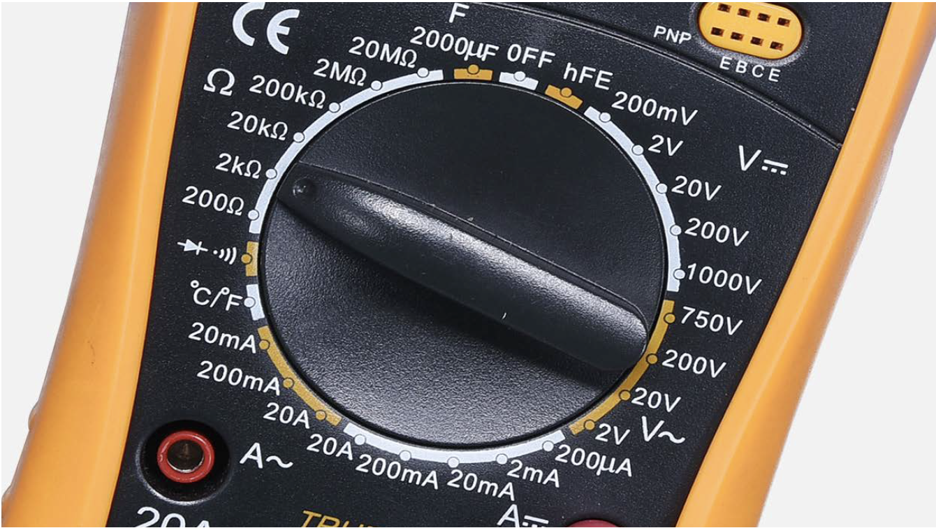
Set multimeter to resistance gear.
Step 4
Measure resistance of fridge temp. sensor from terminal in PCB area.
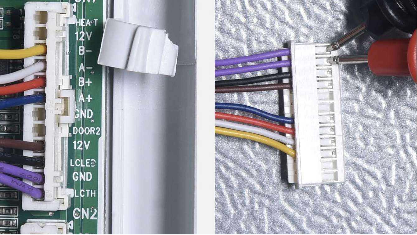
Step 5
Take note of value.
Step 6
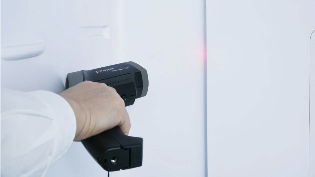
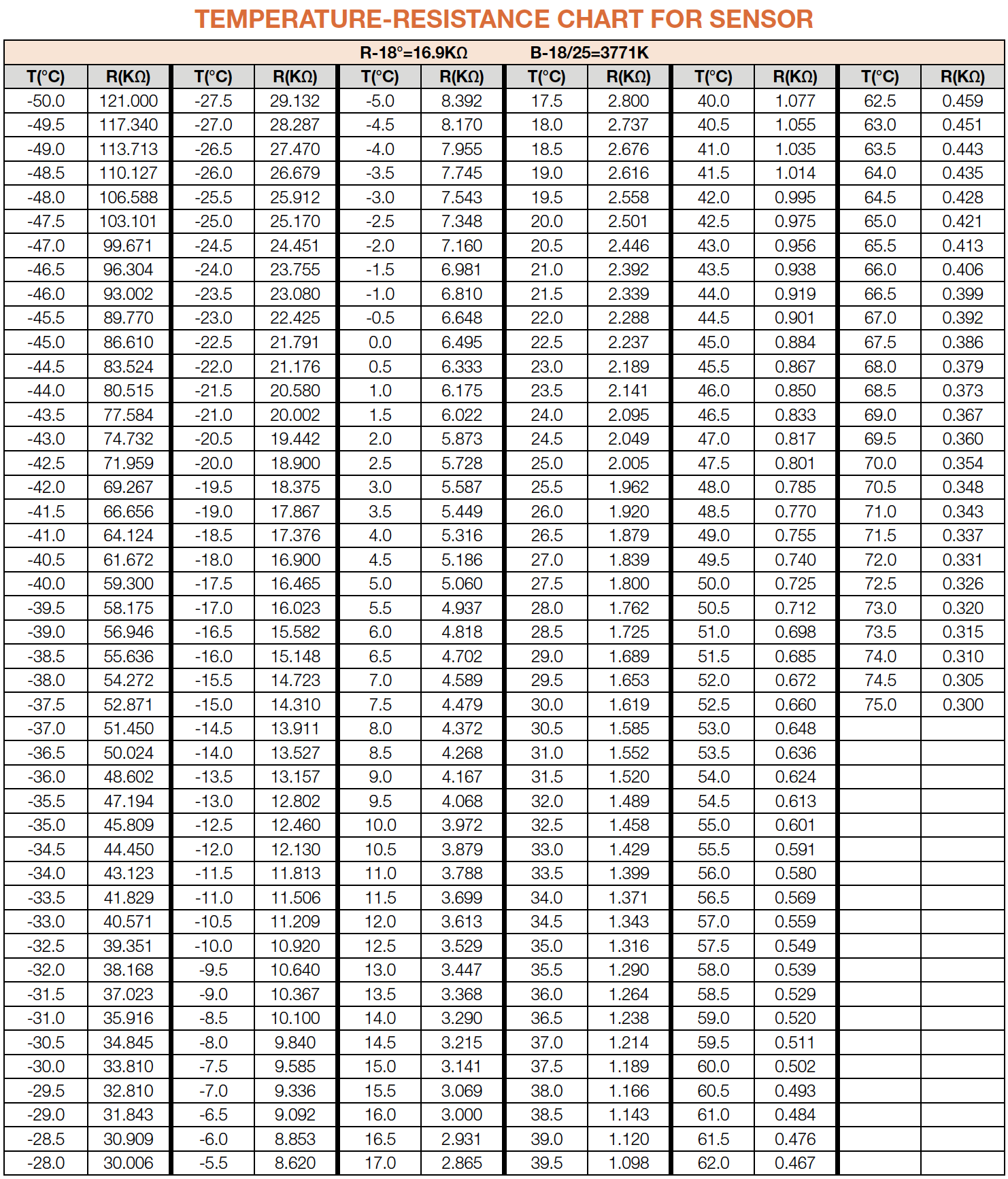
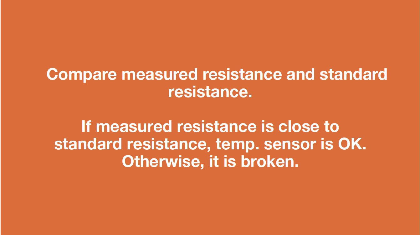
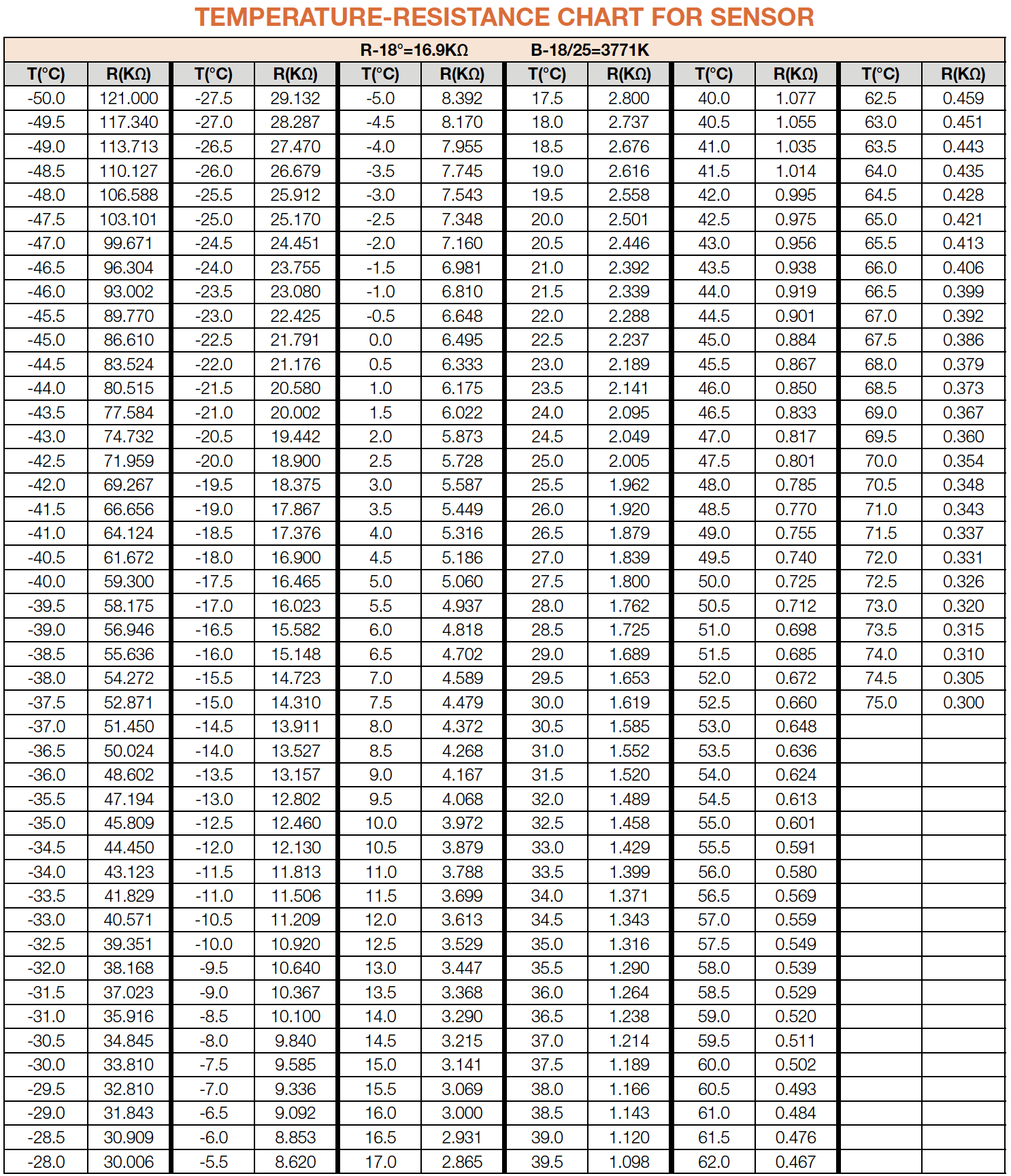
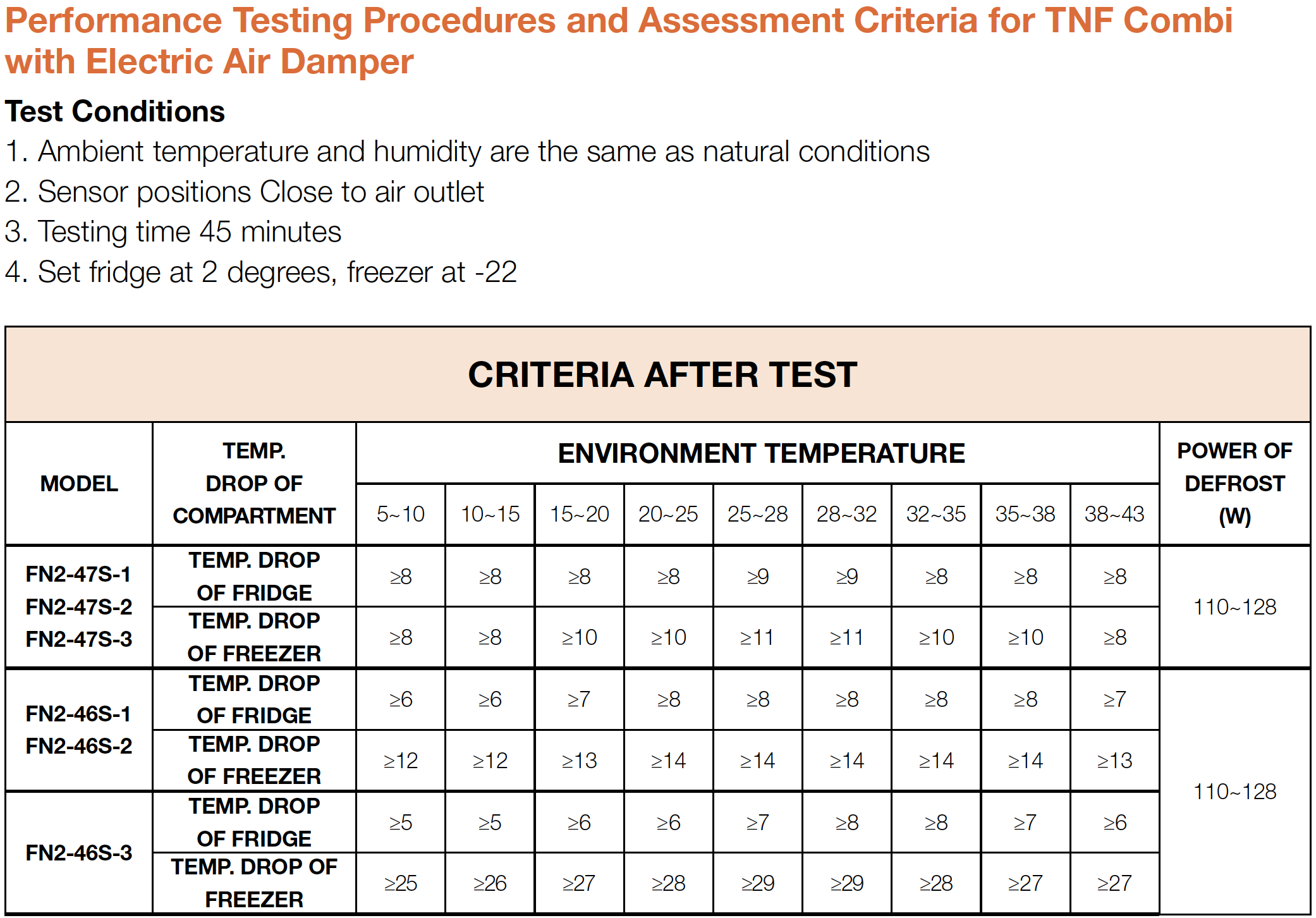
Measure the temperature of fridge temp. sensor. Use the measured temperature to find the standard resistance value in Temperature- Resistance Chart for Sensor.

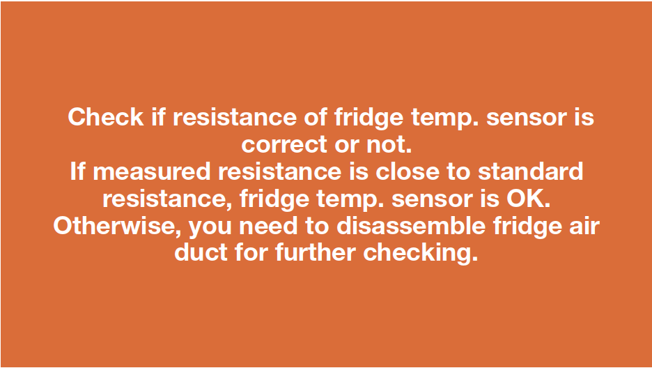
DIAGNOSIS 1


PROCEDURE 1
Step 1
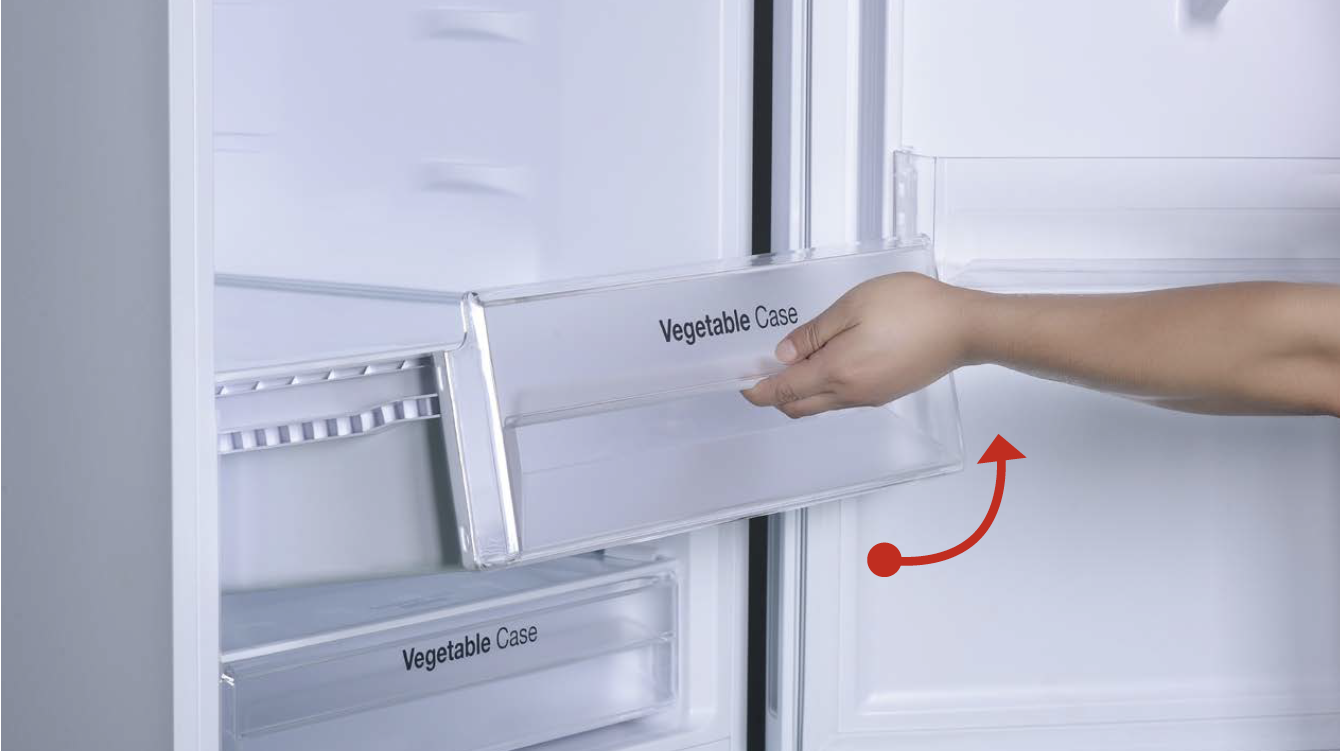
Remove crispers.
Step 2
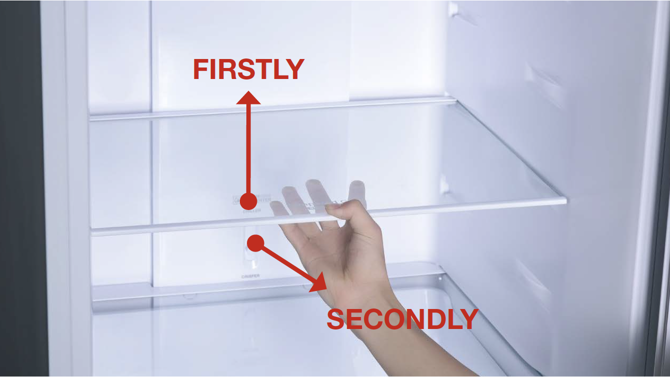
Remove shelves.
Step 3
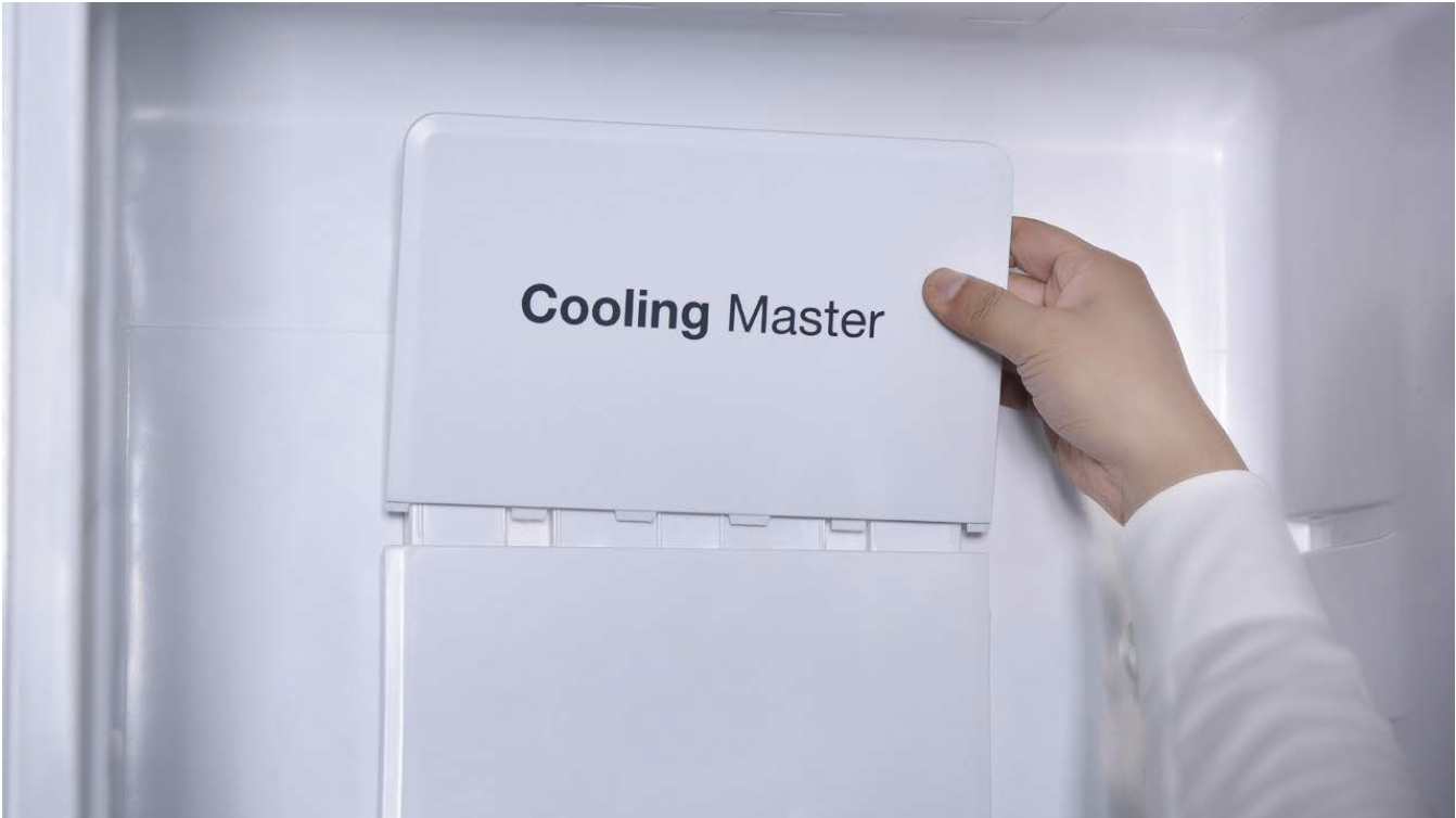
Loosen the decorative plate and remove.
Step 4
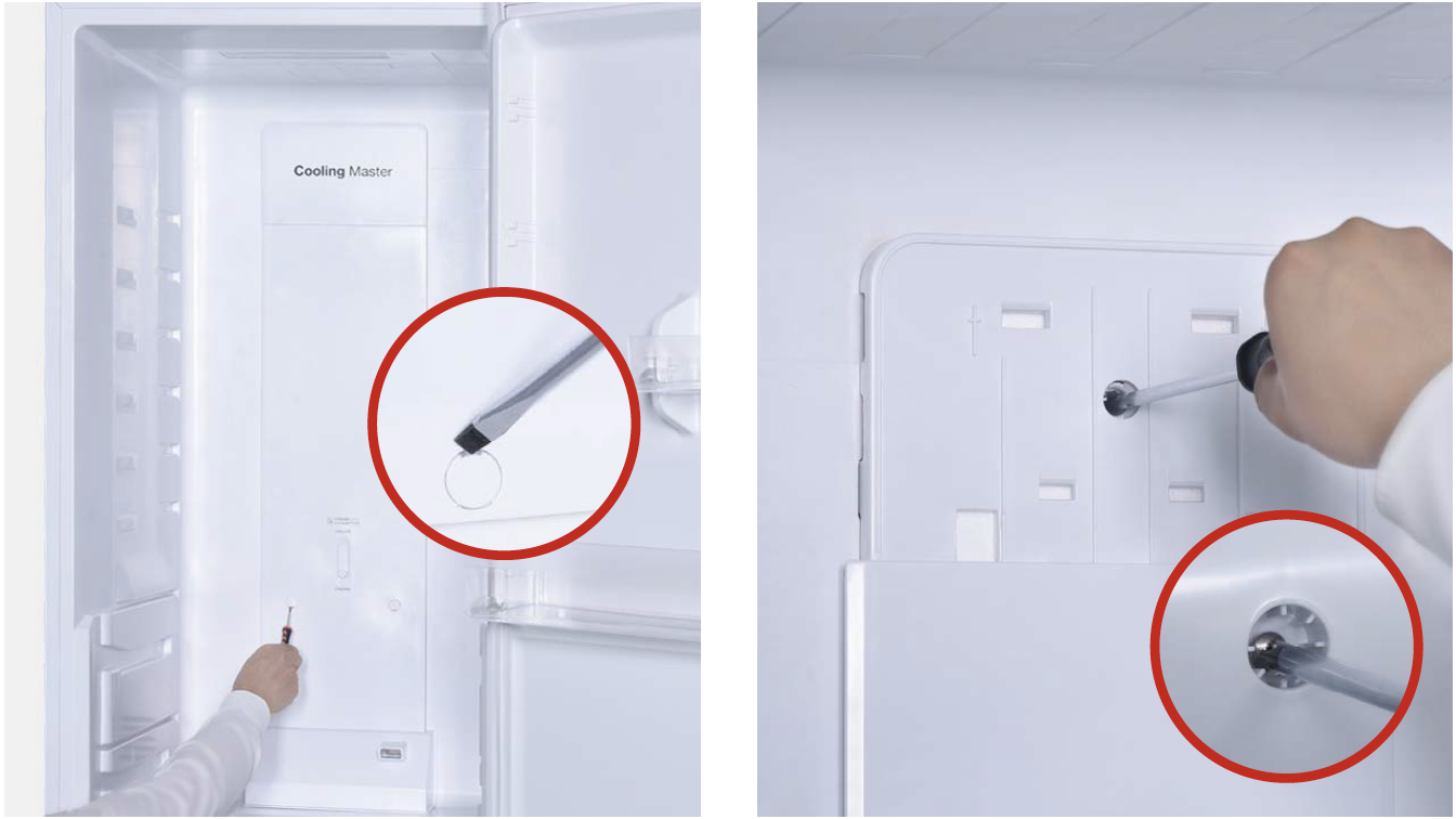
Remove the screw covers on the air duct with slotted screw driver.
Step 5
Unscrew the screws (total of three) with Cross-head screw driver.
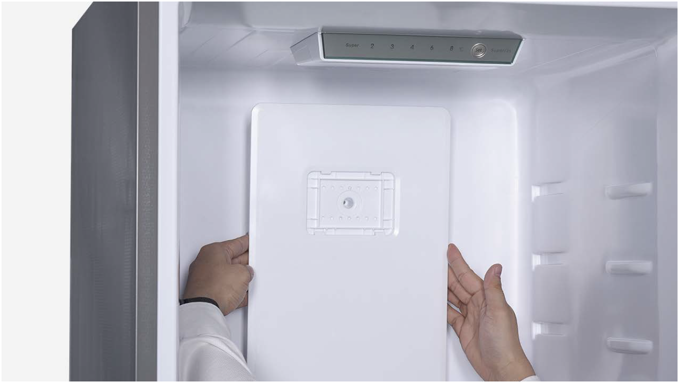
Step 6
Lift the air duct up slightly and pull it out.
CHECK AND TEST 2
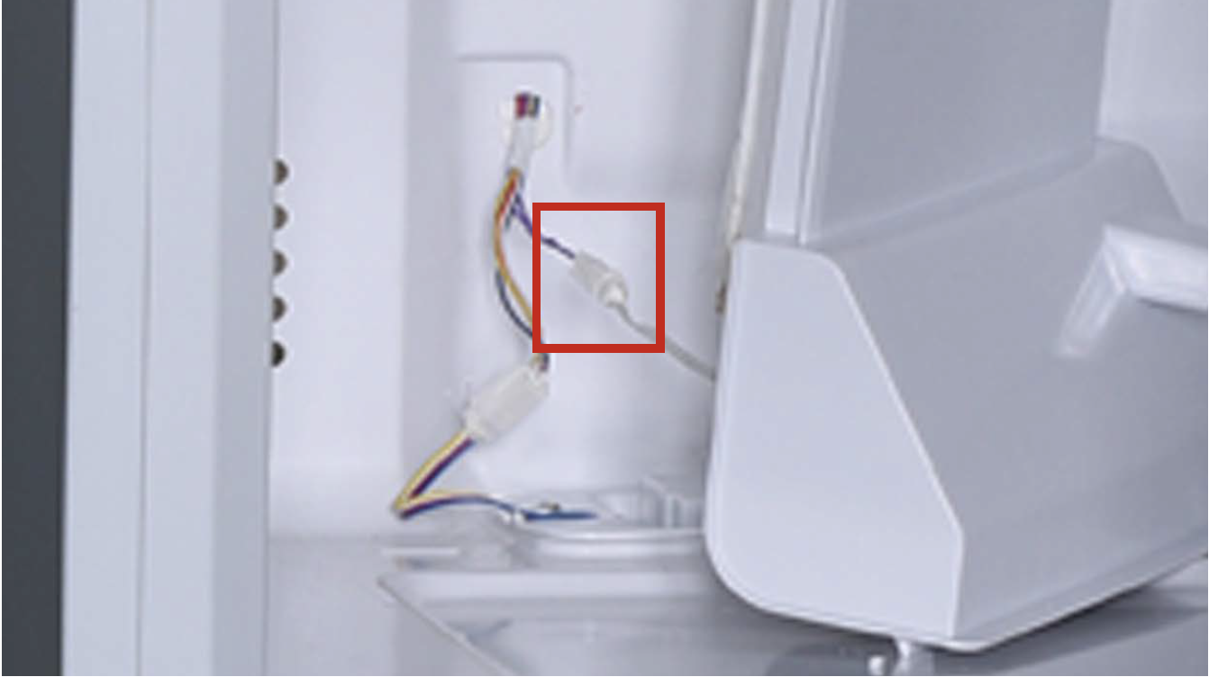
Step 1
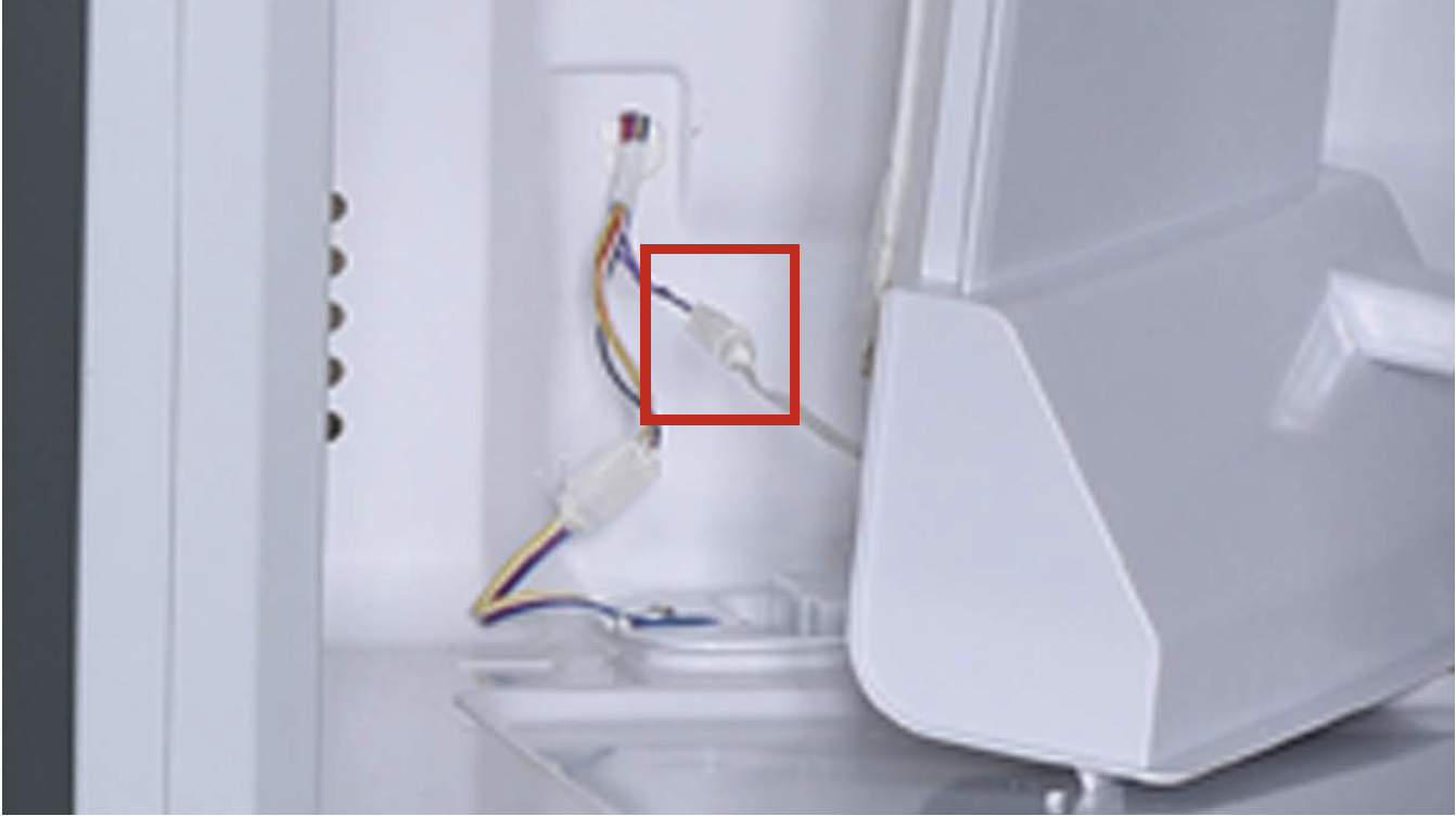
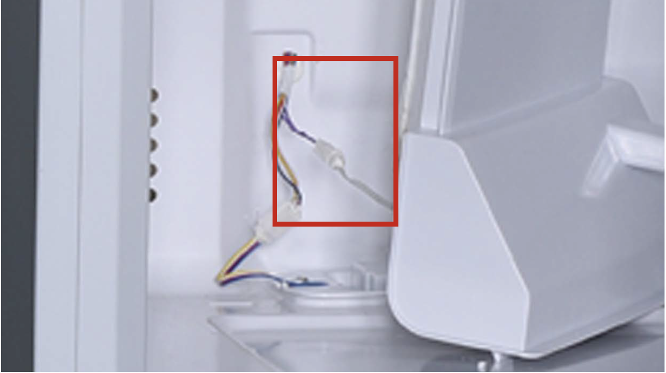
Check if terminal is properly inserted to final position.
If not, reinsert it.
Step 2
Check if wires of fridge temp. sensor are damaged or not.
PROCEDURE 2

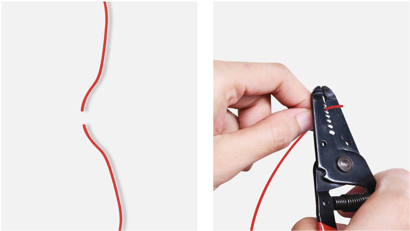
Step 1
Cut wire off.
Step 2
Peel off the sleeves.
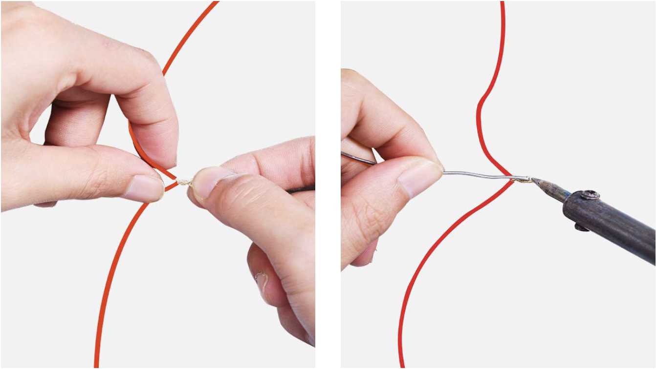
Step 3
Check to ensure proper wire order and reconnect them.
Step 4
Tin soldering.
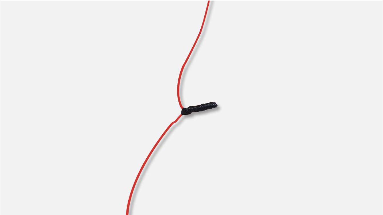
Step 5
Cover connecting point with electrical tape.
CHECK AND TEST 3
Step 1
Disconnect terminal of fridge temp. sensor.
Step 2
Measure resistance of fridge sensor from terminal in fridge air duct cover.
Step 3
Measure the temperature of fridge temp. sensor. Use the measured temperature to find the standard resistance value in Temperature- Resistance Chart for Sensor.
DIAGNOSIS 3

PROCEDURE 2

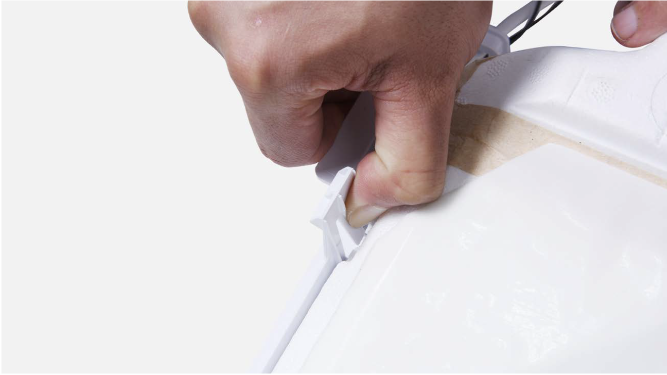
Step 1
Release the clasp.
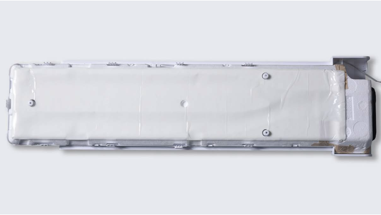
Step 2
Remove the foam air duct.
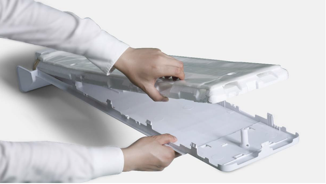
Step 3
Remove tape.
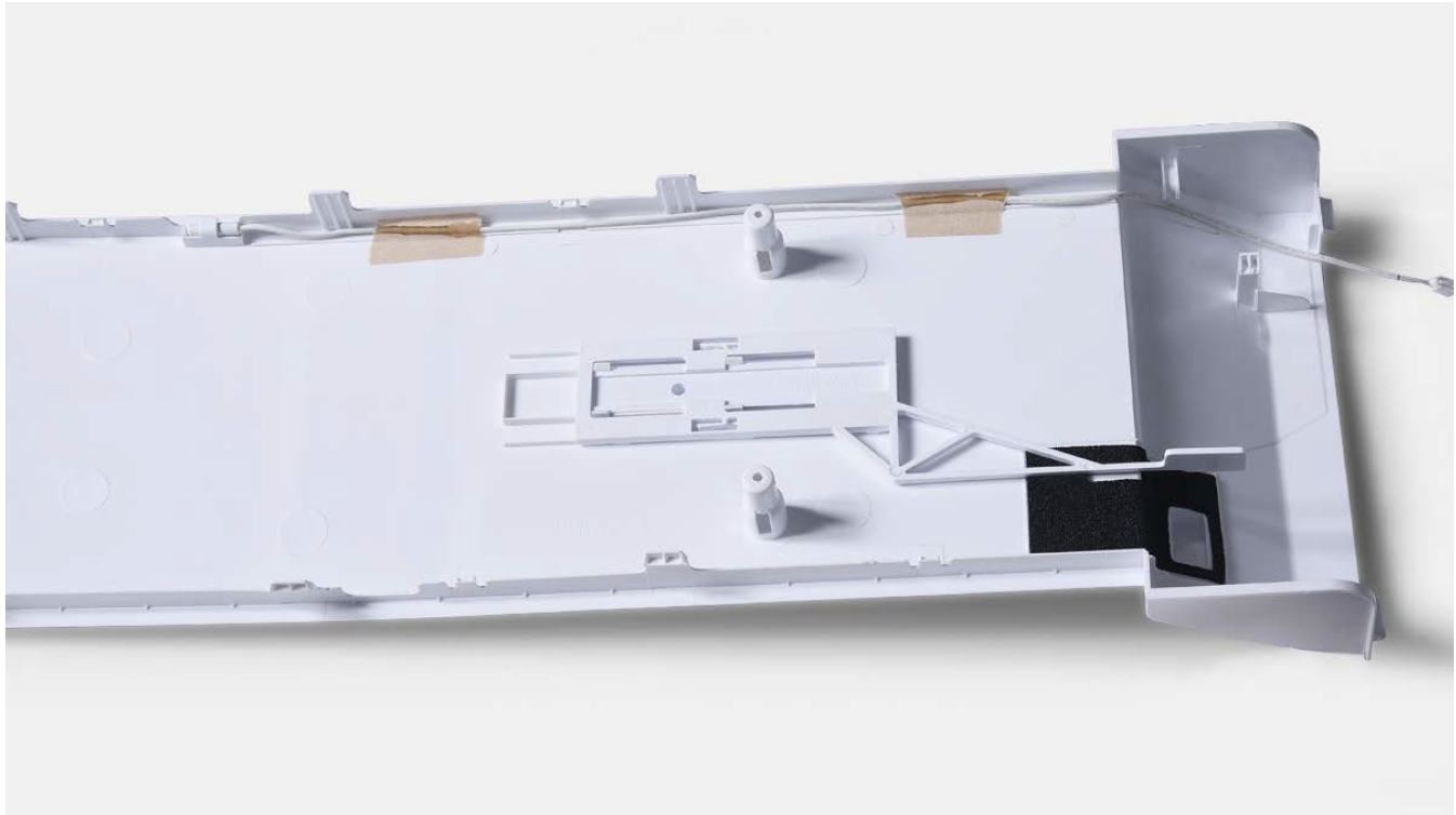
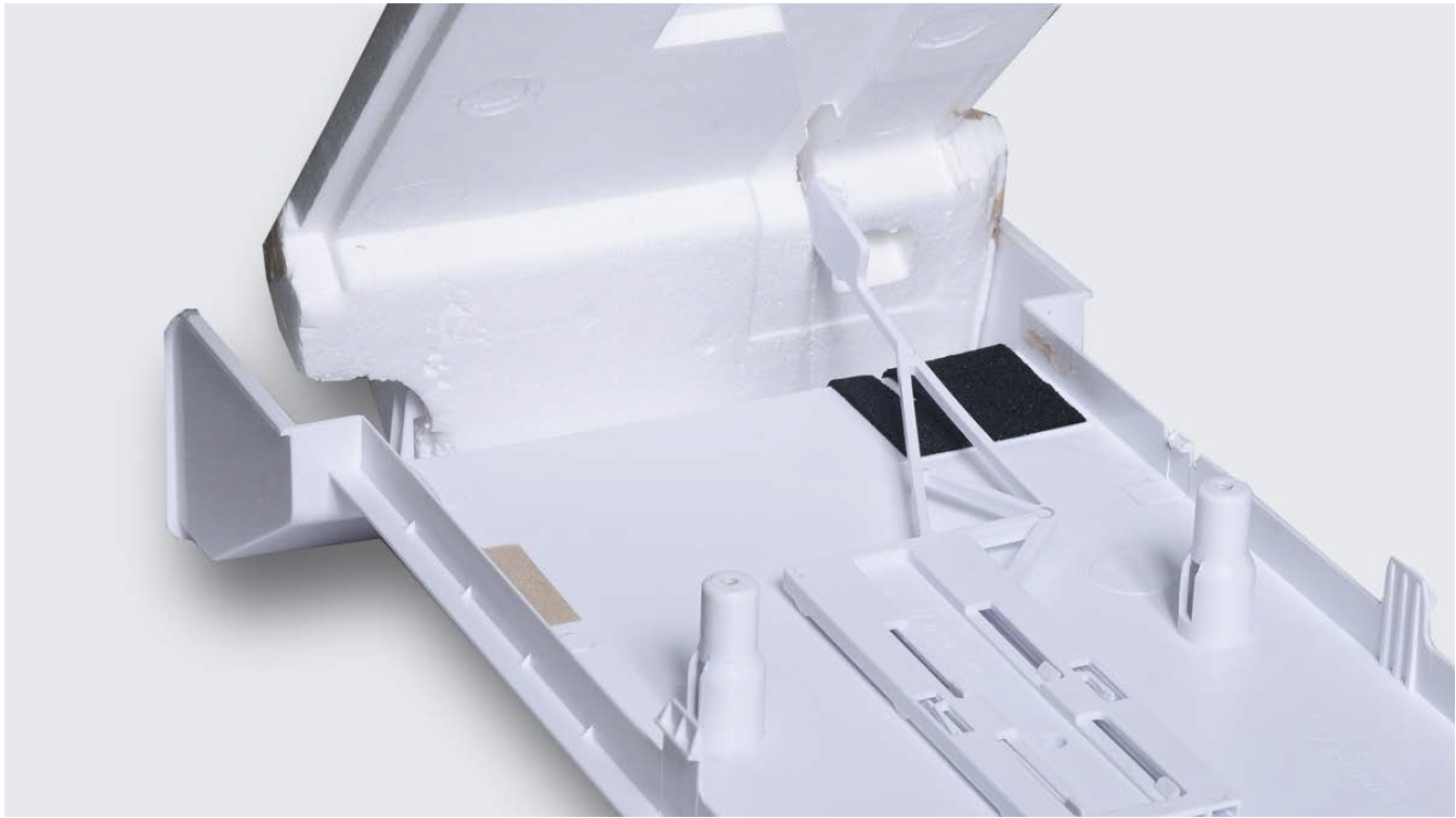
Step 4
Remove the broken sensor, and replace it with a new one.
Reverse steps above to
reinstall the air duct.
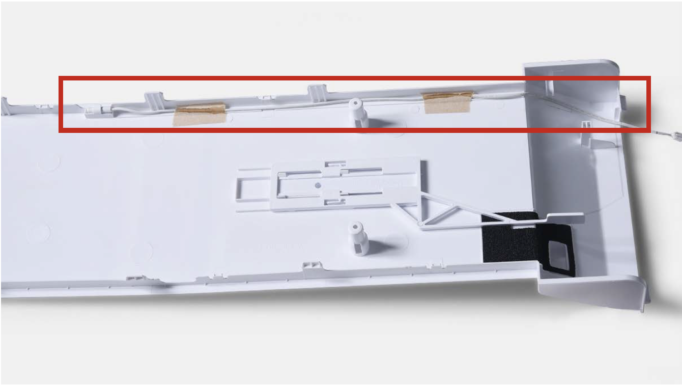
Please pay attention to
bellow key points.
Tip 1
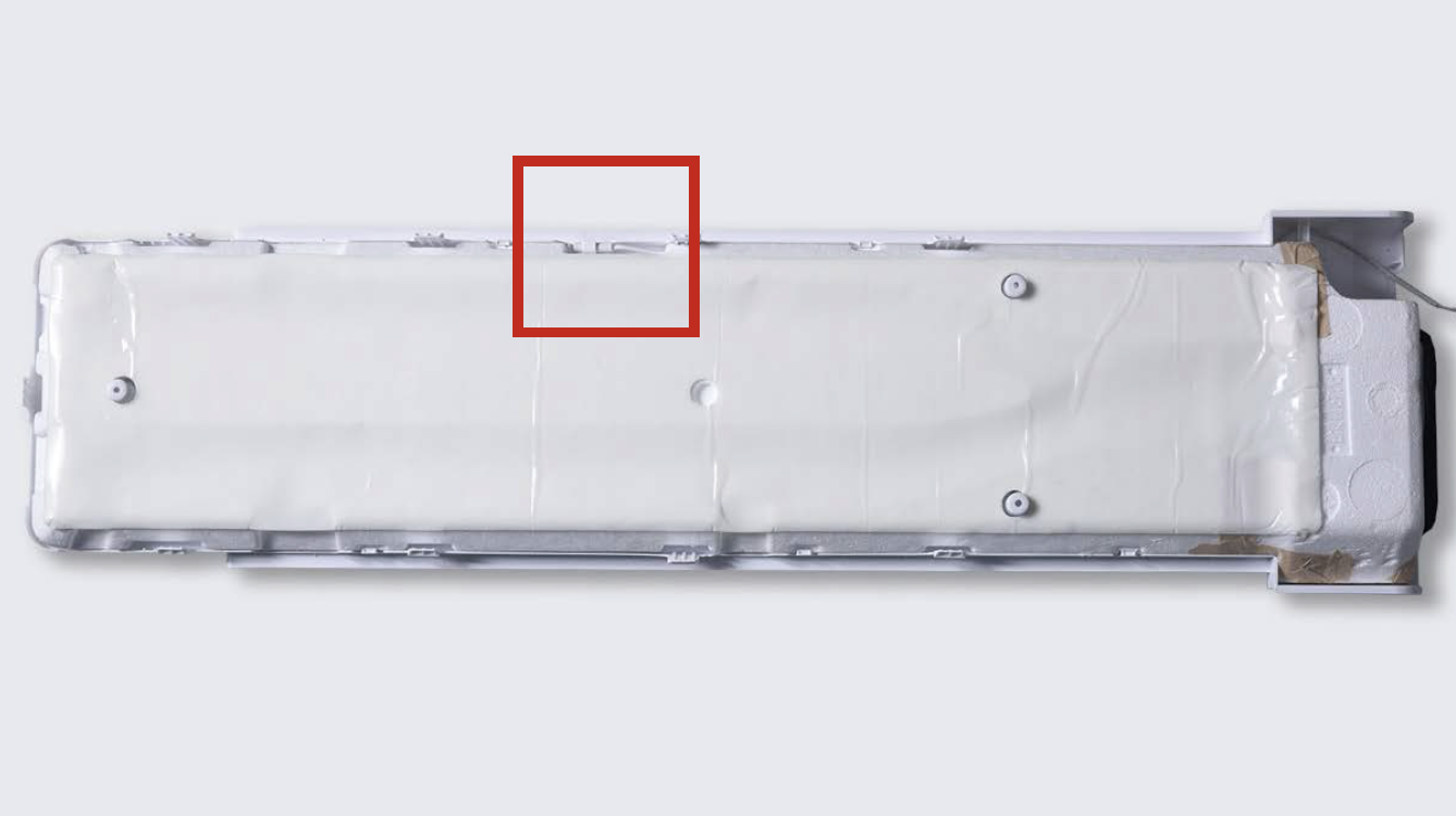
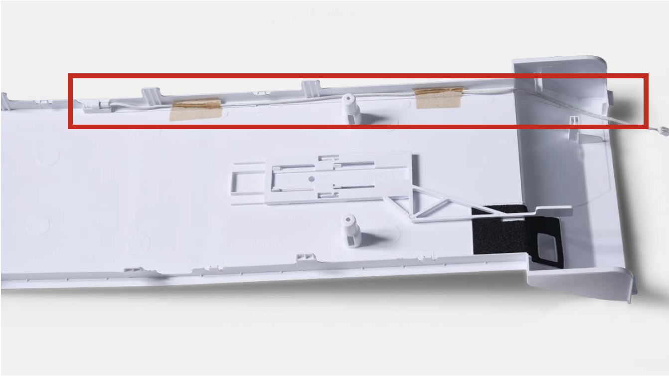
Fasten sensor properly on air duct cover, as shown in the picture on right.
Tip 2
Make sure the sealing sponge is in good condition.
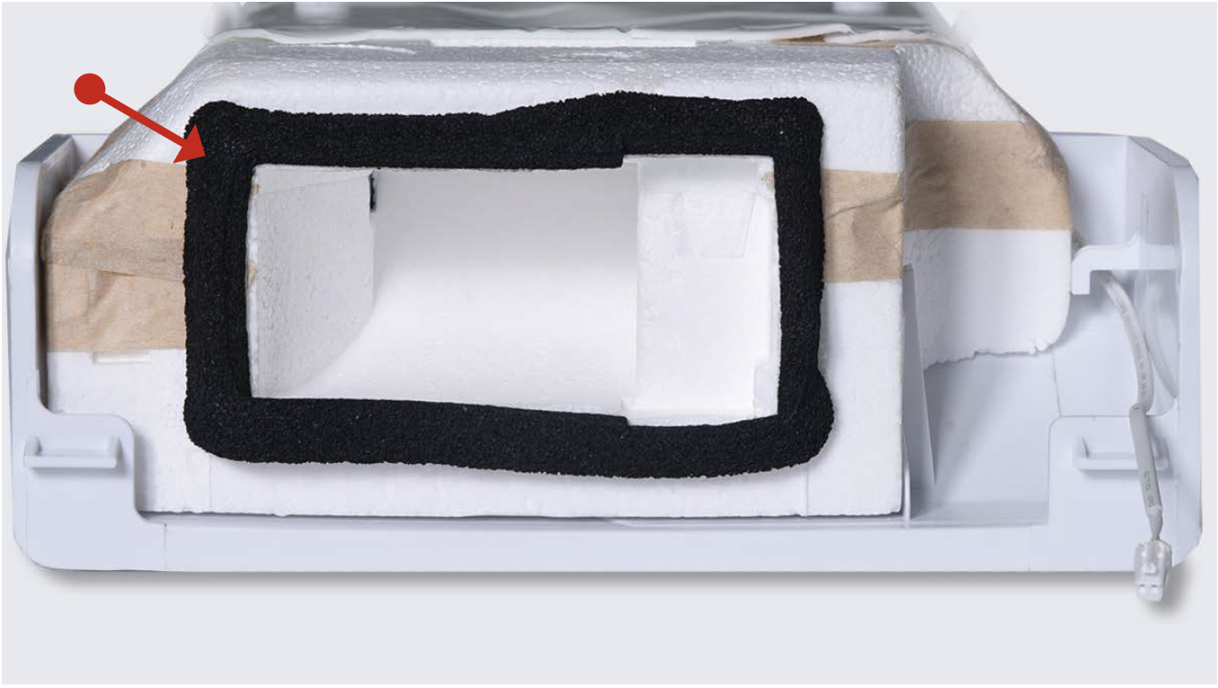
Tip 3
Make sure back cover of the air duct is not broken.
Tip 4
Make sure chiller temperature controller is installed to correct position.
CHECK AND TEST 4
Step 1
Set multimeter to resistance gear.
Step 2
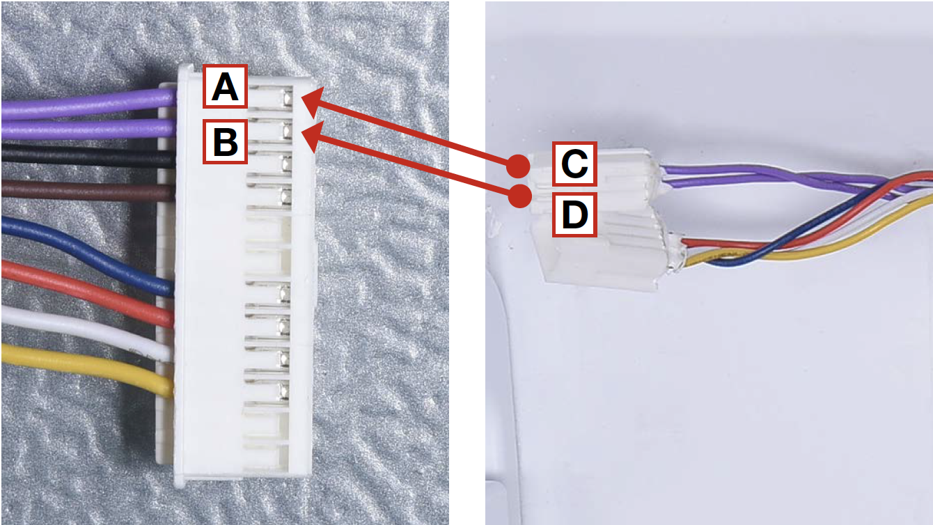
Put one detector into one end of wires in PCB area, and another detector into one end of wires in fridge air duct cover.
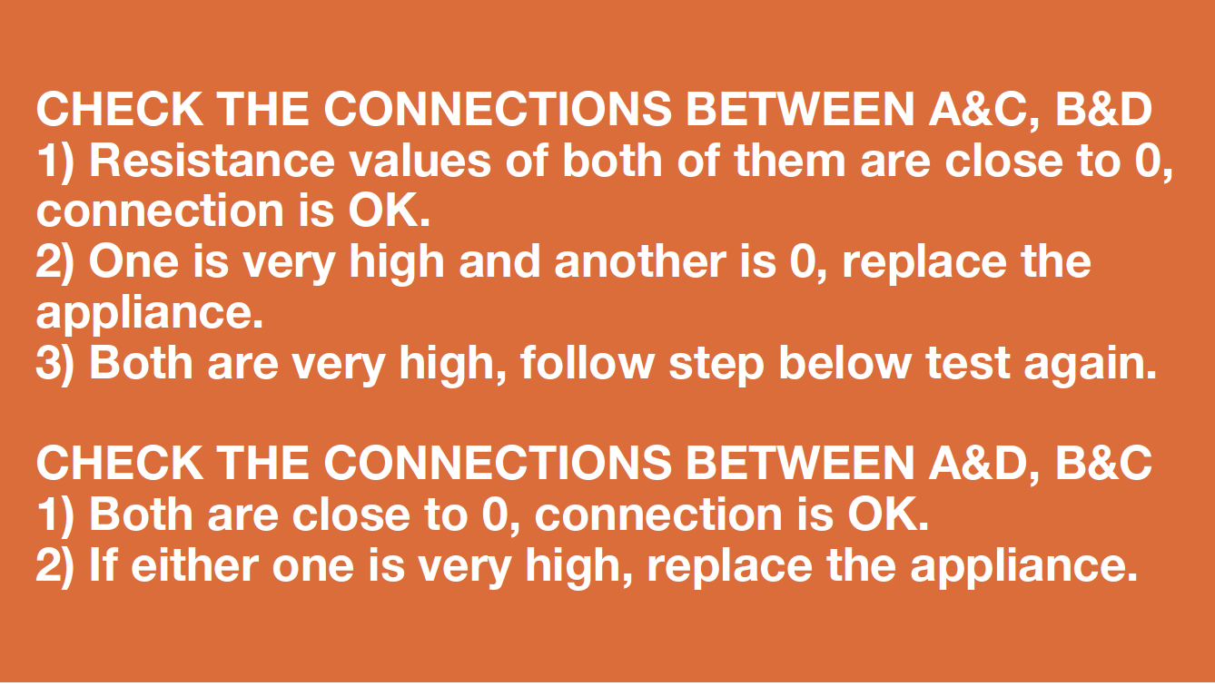
DIAGNOSIS 4


PROCEDURE 3
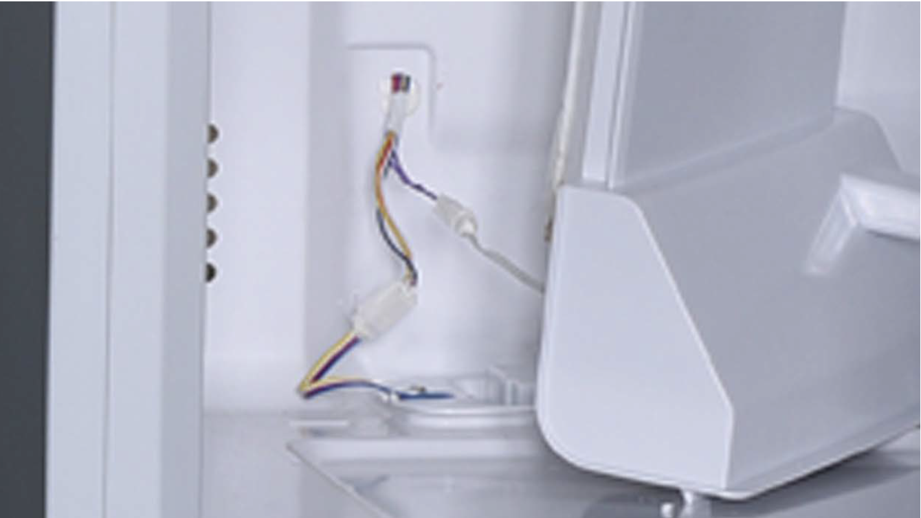
Tip 1
Push terminals into final position, and then move wires onto cavity to avoid crushing wires with edge of air duct.
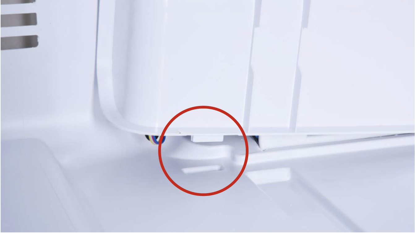
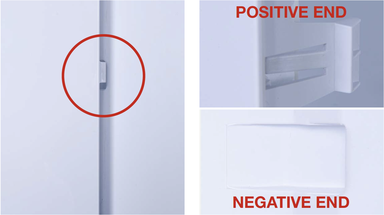
Tip 2
When reinstalling the air duct, first put the positive end of buckle (on the bottom) into the negative end.
Tip 3
Later, fasten the buckles on the top with same method.
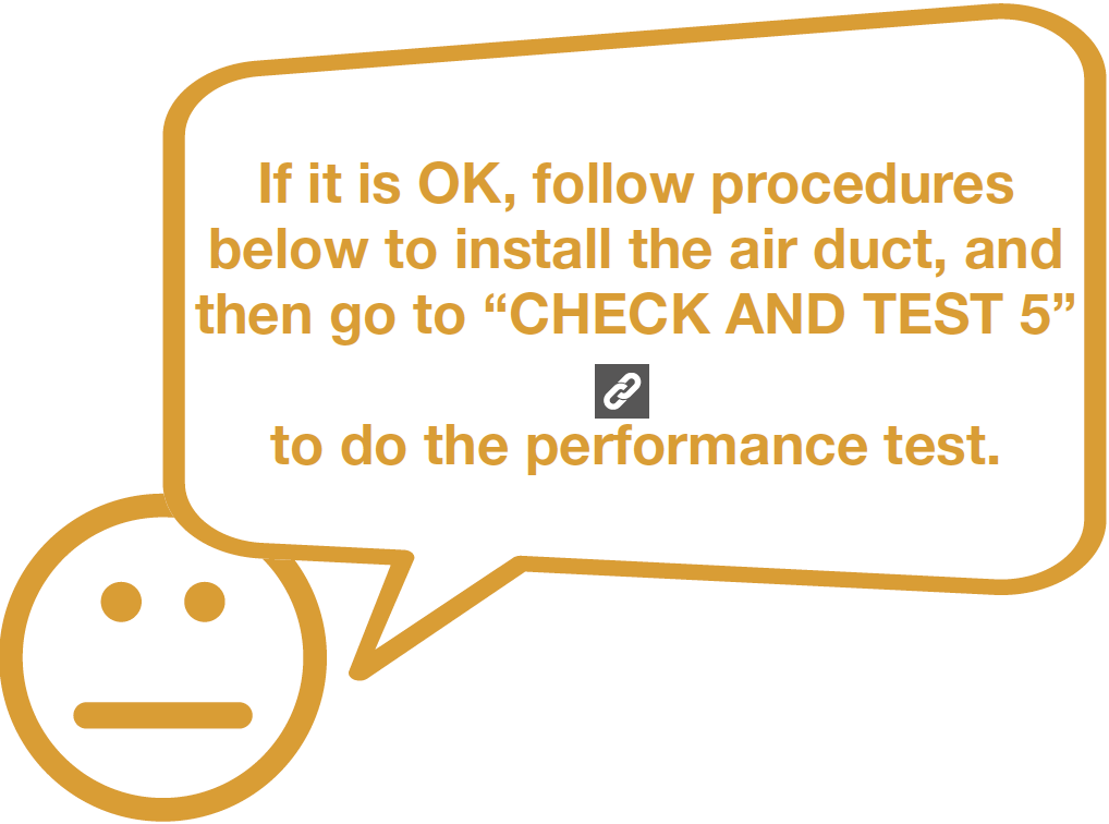
CHECK AND TEST 5

DIAGNOSIS 5


GO BACK TO COMPONENT LIST