8.2 RELIABILITY FAULTS:
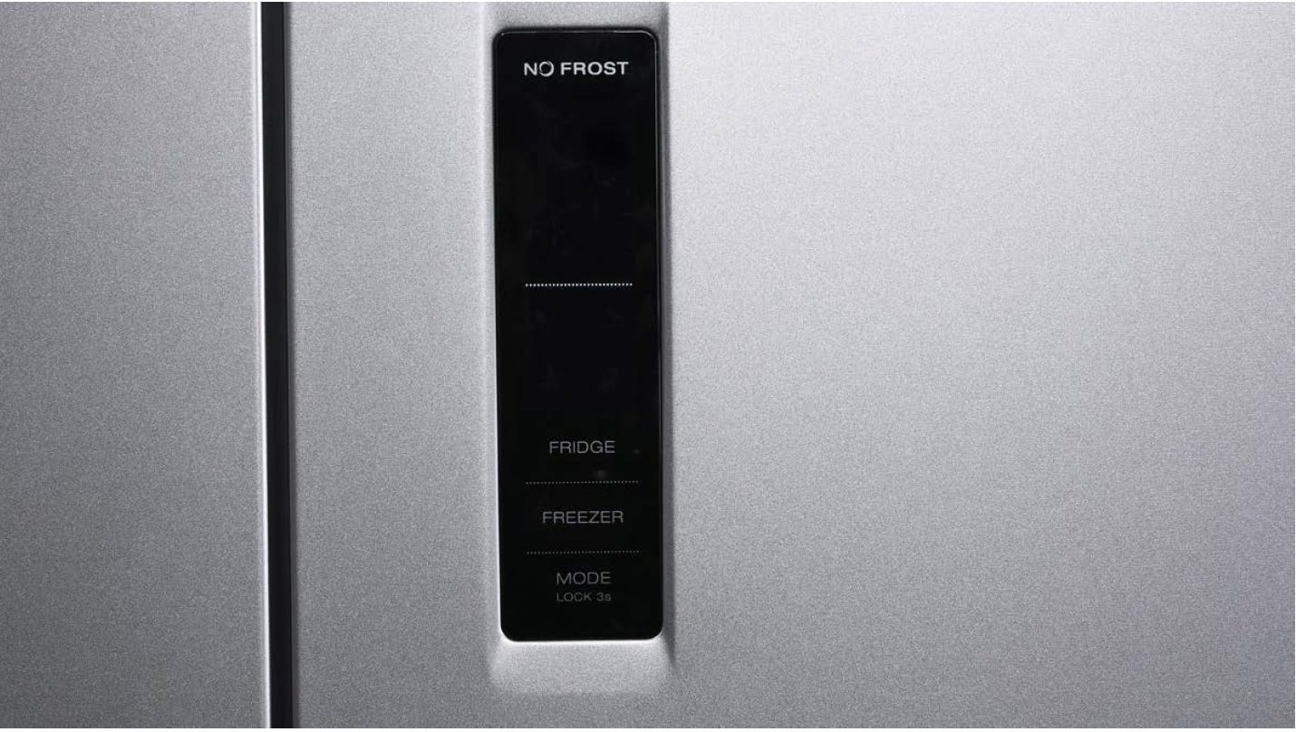
WRONG OR NO ICONS ON DISPLAY


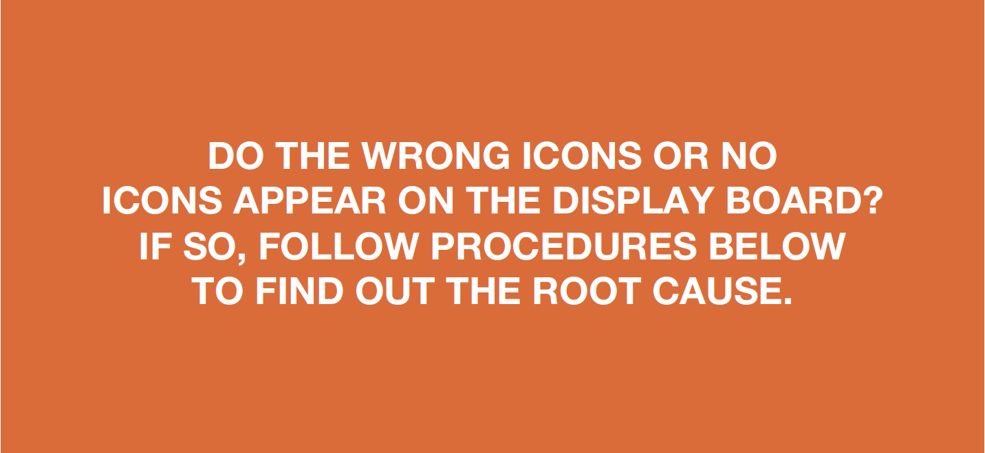
CHECK AND TEST 1
Step 1
If you verify that the wrong icons or no icons are shown on display or icons are flashing...

DIAGNOSIS 1
CHECK AND TEST 2
Step 1
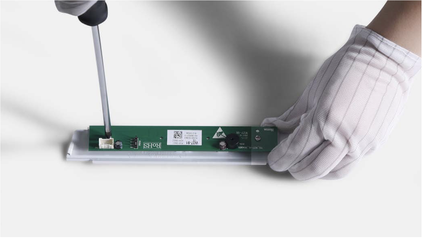
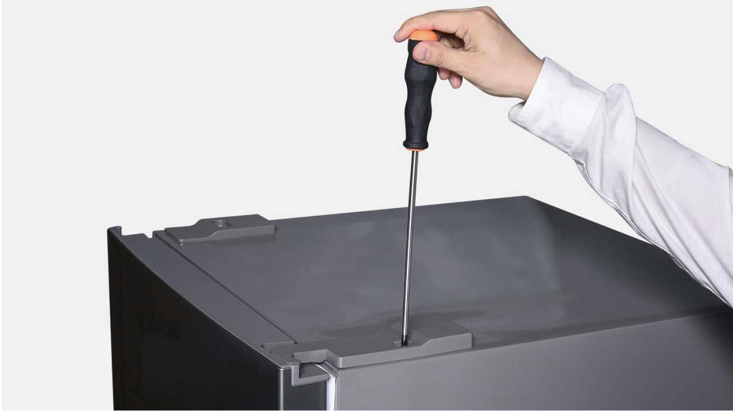
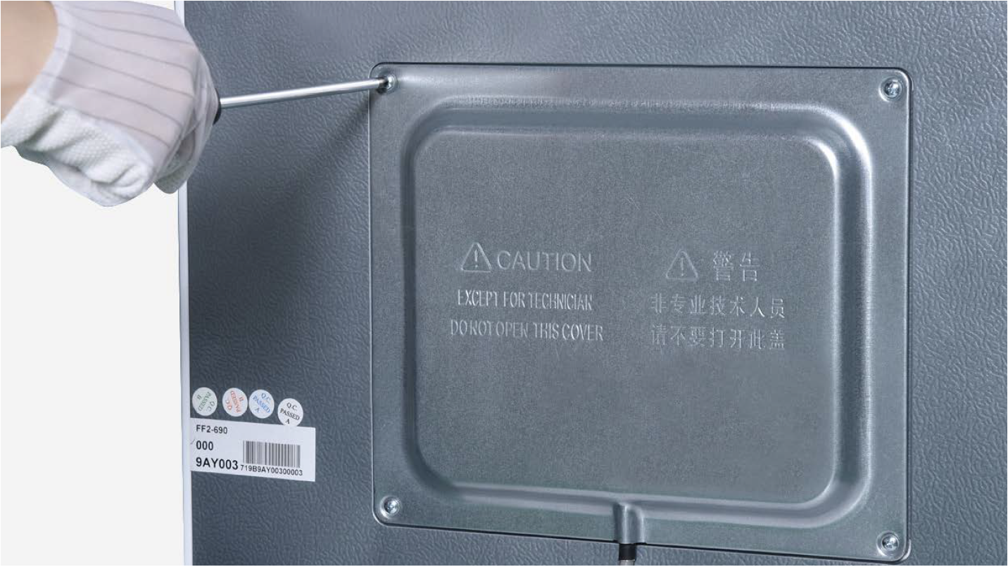
Unscrew cover of mainboard with a cross-head screwdriver.

Step 2
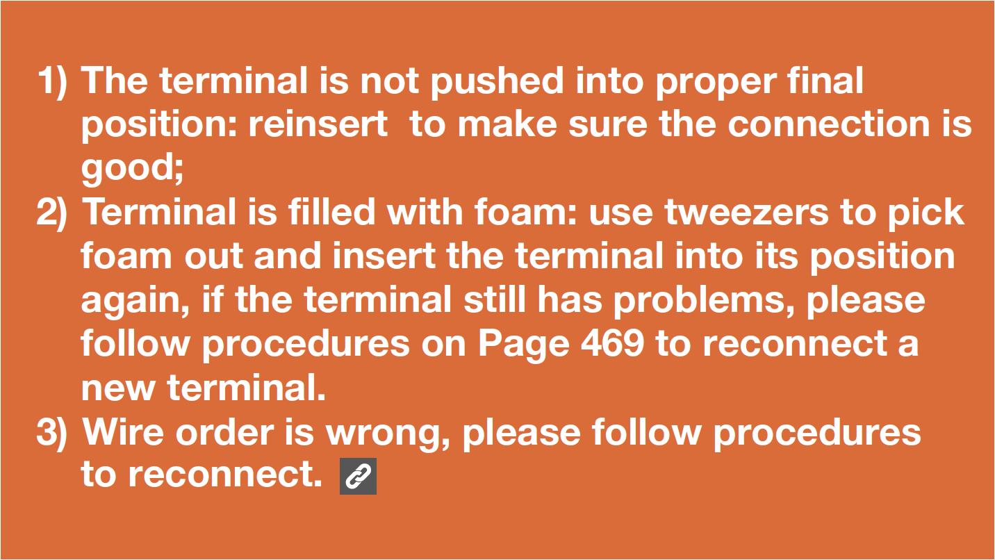
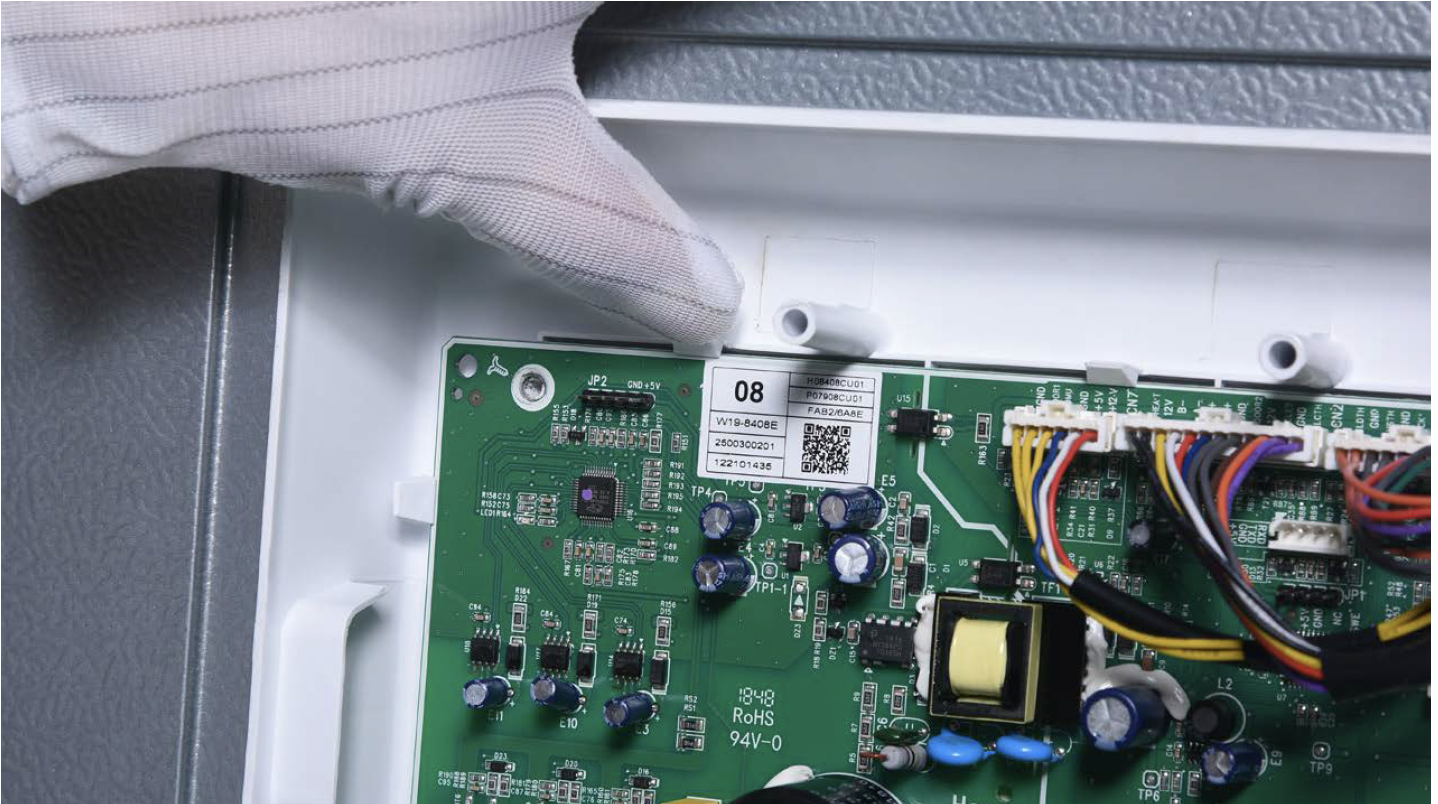
Check if terminal in PCB area is inserted to final position.
If not, reinsert it to final position.
Step 3
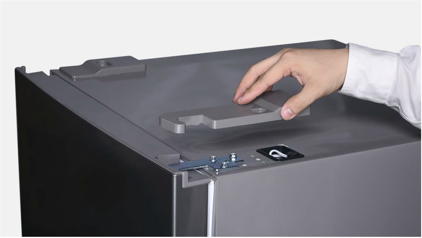
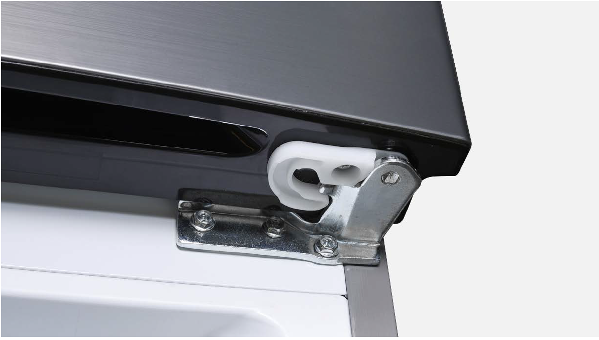
Unscrew hinge cover.
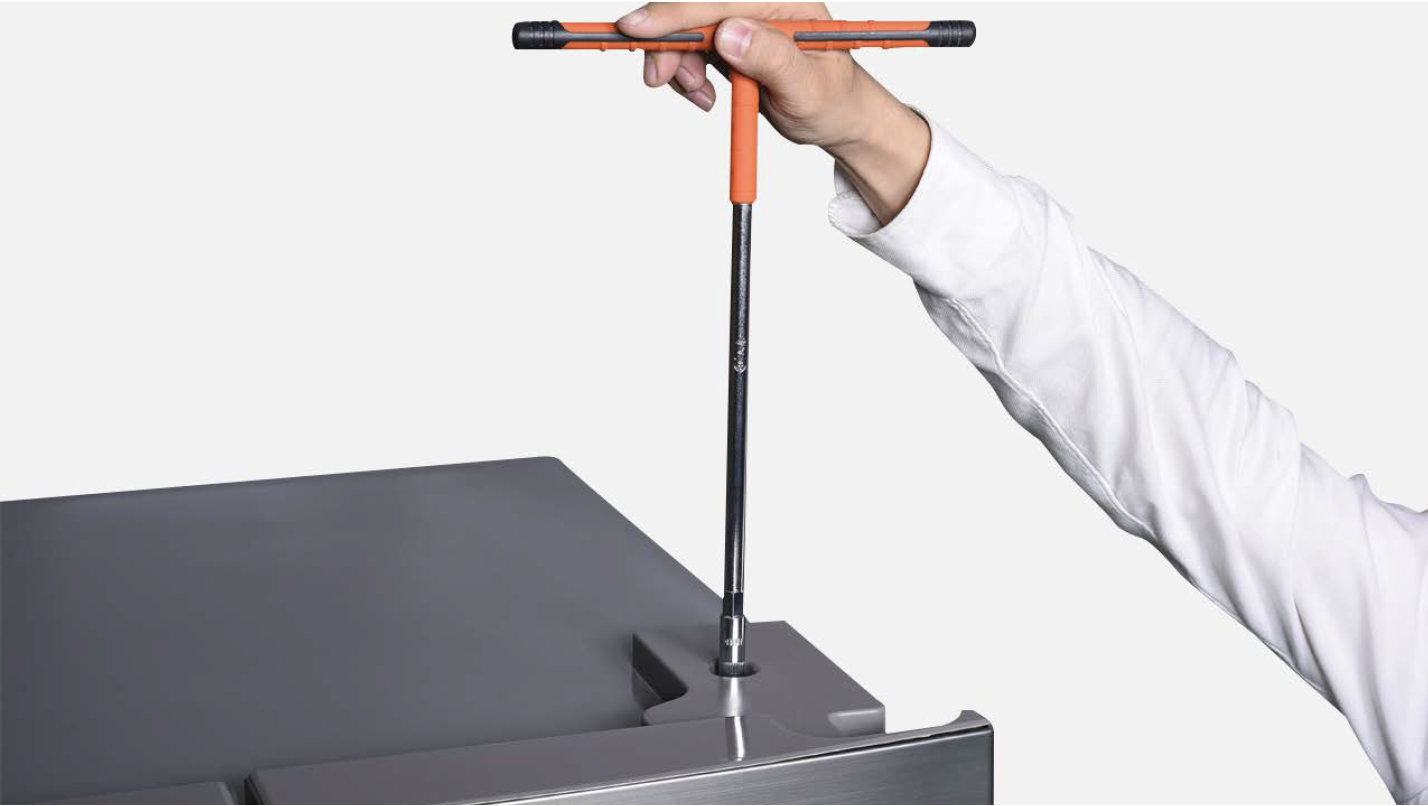
Step 4
Check if terminal in hinge cover is inserted to final position.
If not, reinsert it to final position.

DIAGNOSIS 2

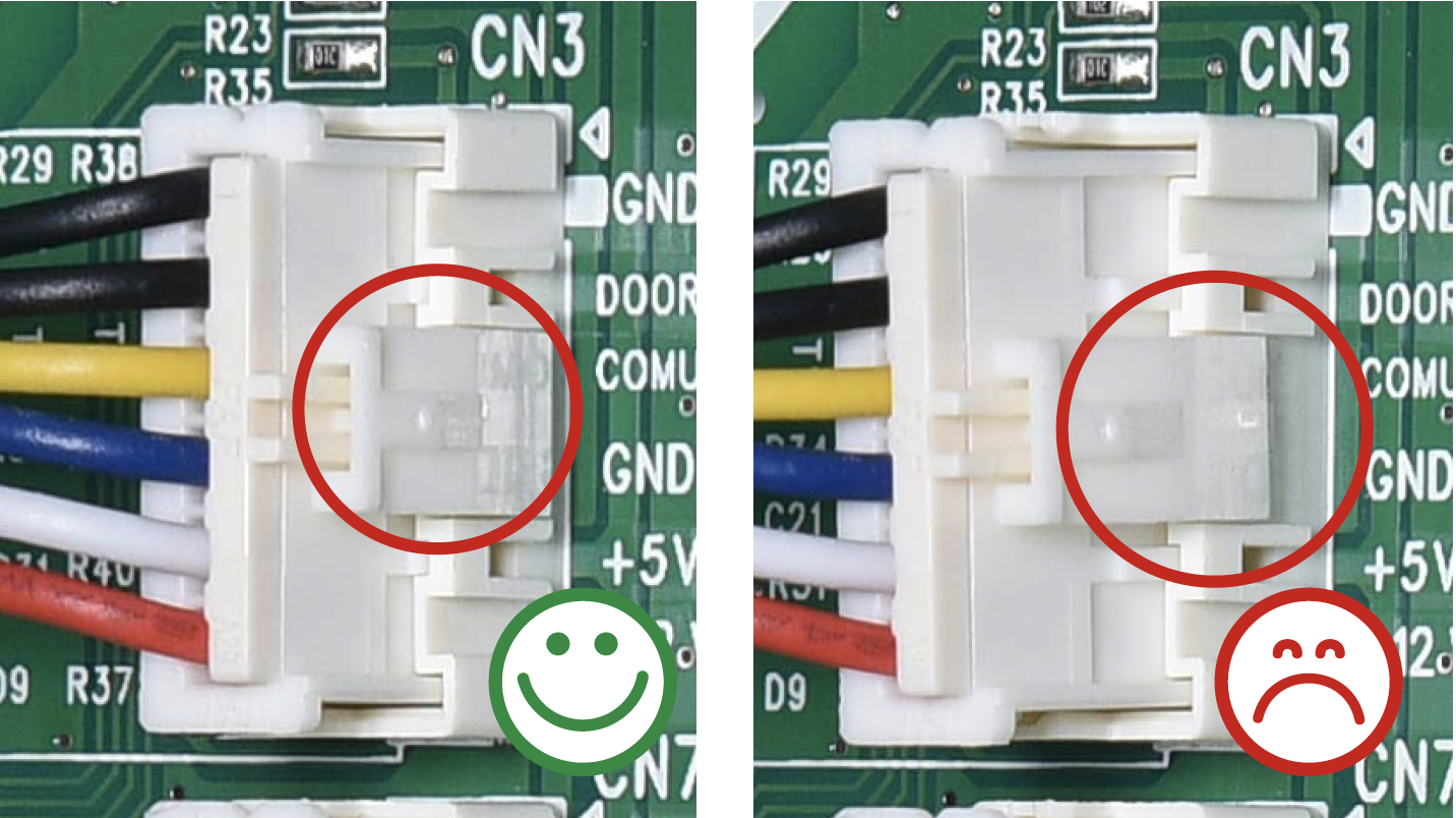
CHECK AND TEST 3
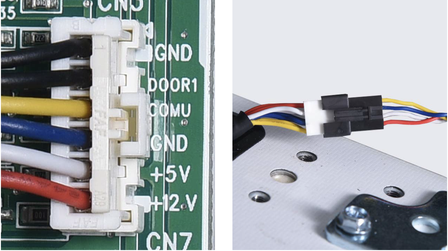
Step 1
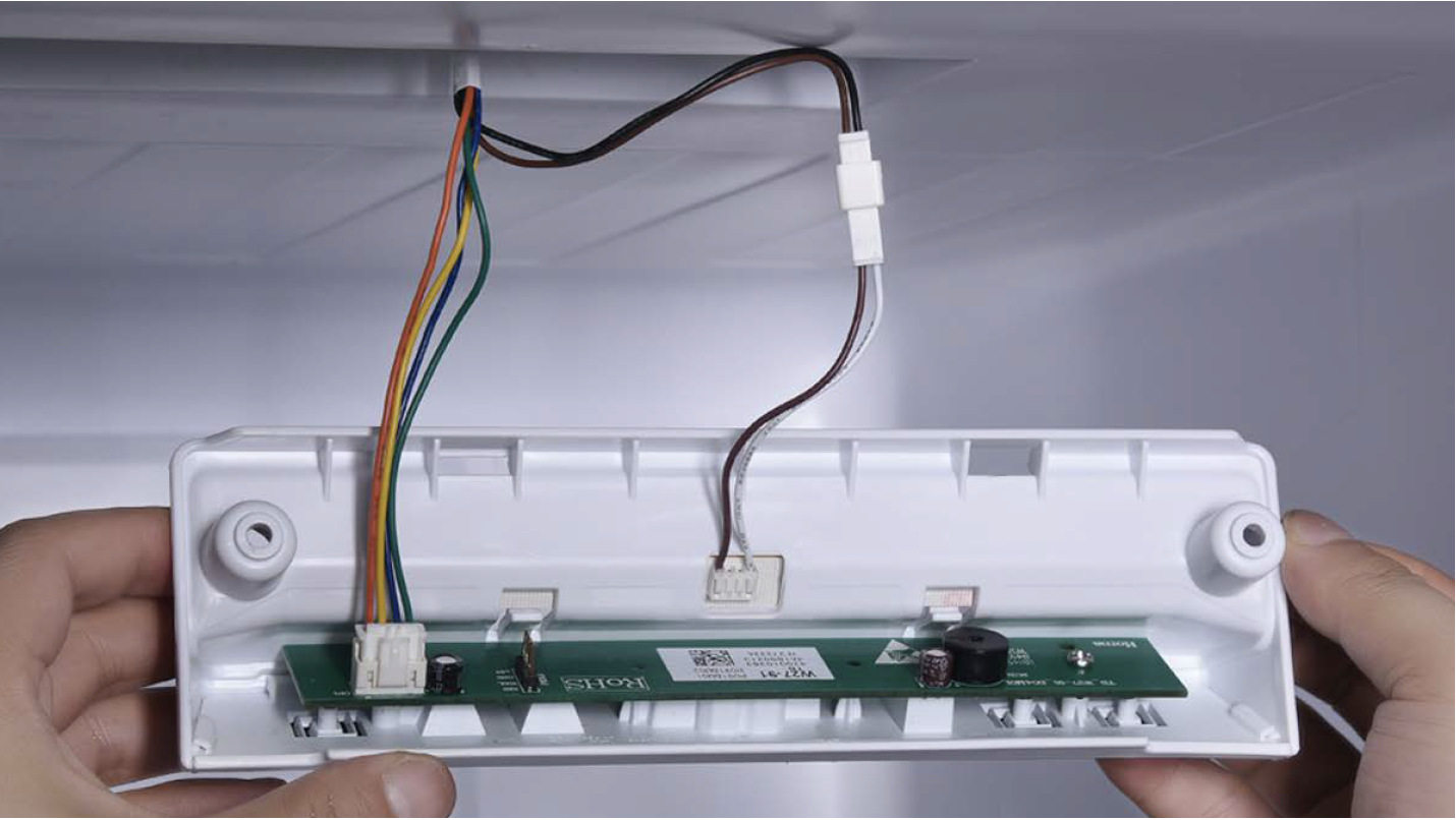
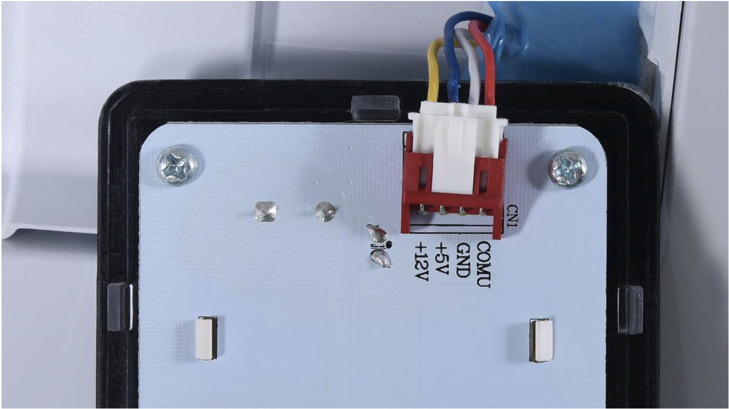
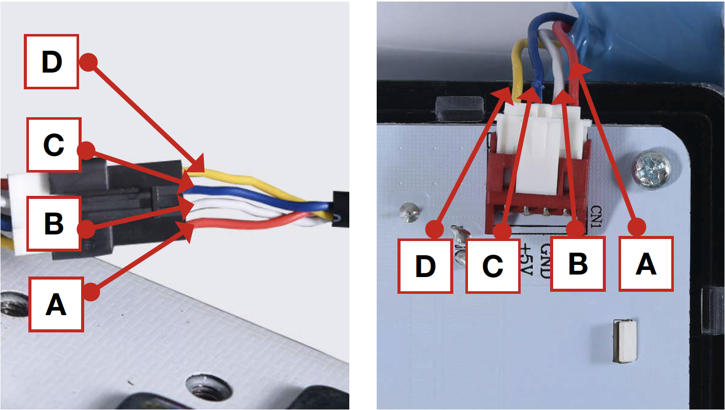
Check if wire order in PCB area and hinge cover area are correct or not.
Right picture shows the correct wire order.
DIAGNOSIS 3
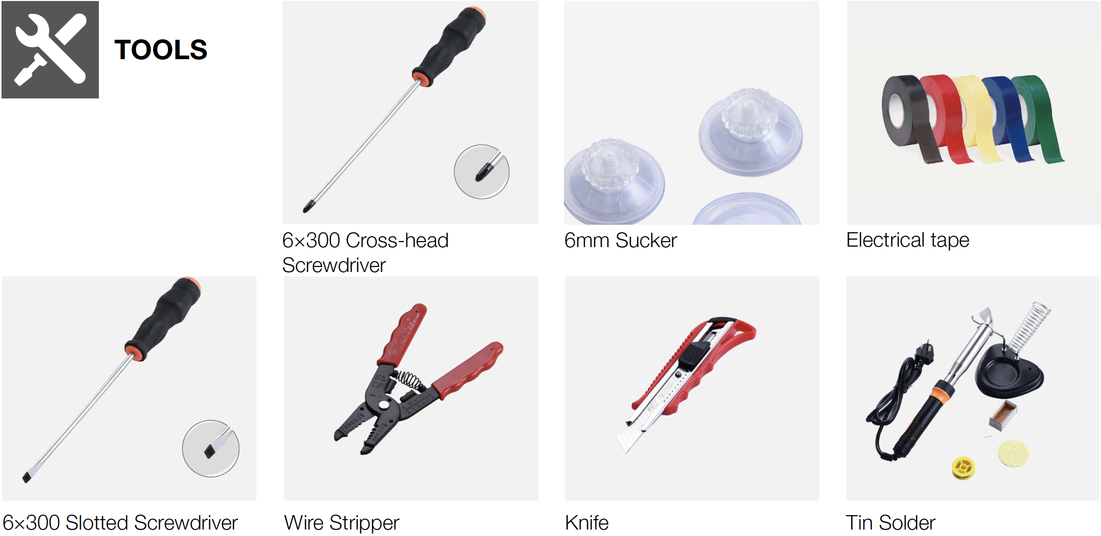
PROCEDURE 1
GENERAL PROCEDURES FOR WIRE RECONNECTION.
Step 1
Cut wire off.

Step 2
Peel off the sleeves.
Step 3
Check to ensure proper wire order and connect them.

Step 4
Tin soldering.
Step 5
Cover connection with electrical tape.


PROCEDURE 2
Step 1
Push a 6mm sucker onto display and turn the knob to strengthen suction force.
Step 2
Wrap a belt around knob to make it easier to pull out of display board.

Tips for installing display.
Tip 1
After connecting terminal, please use tape to fasten wires to avoid crushing with cover.
Tip 2
After putting display
into cavity, press edge
until you hear a clicking
sound, this means the
board is pushed into final
position.
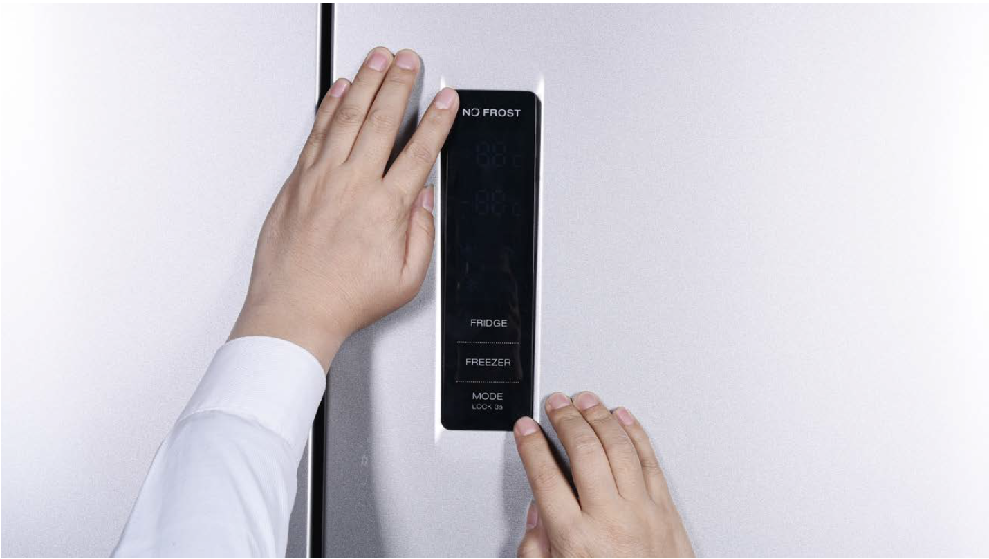
Tip 3
Please press all buttons on display board to make sure it works well.
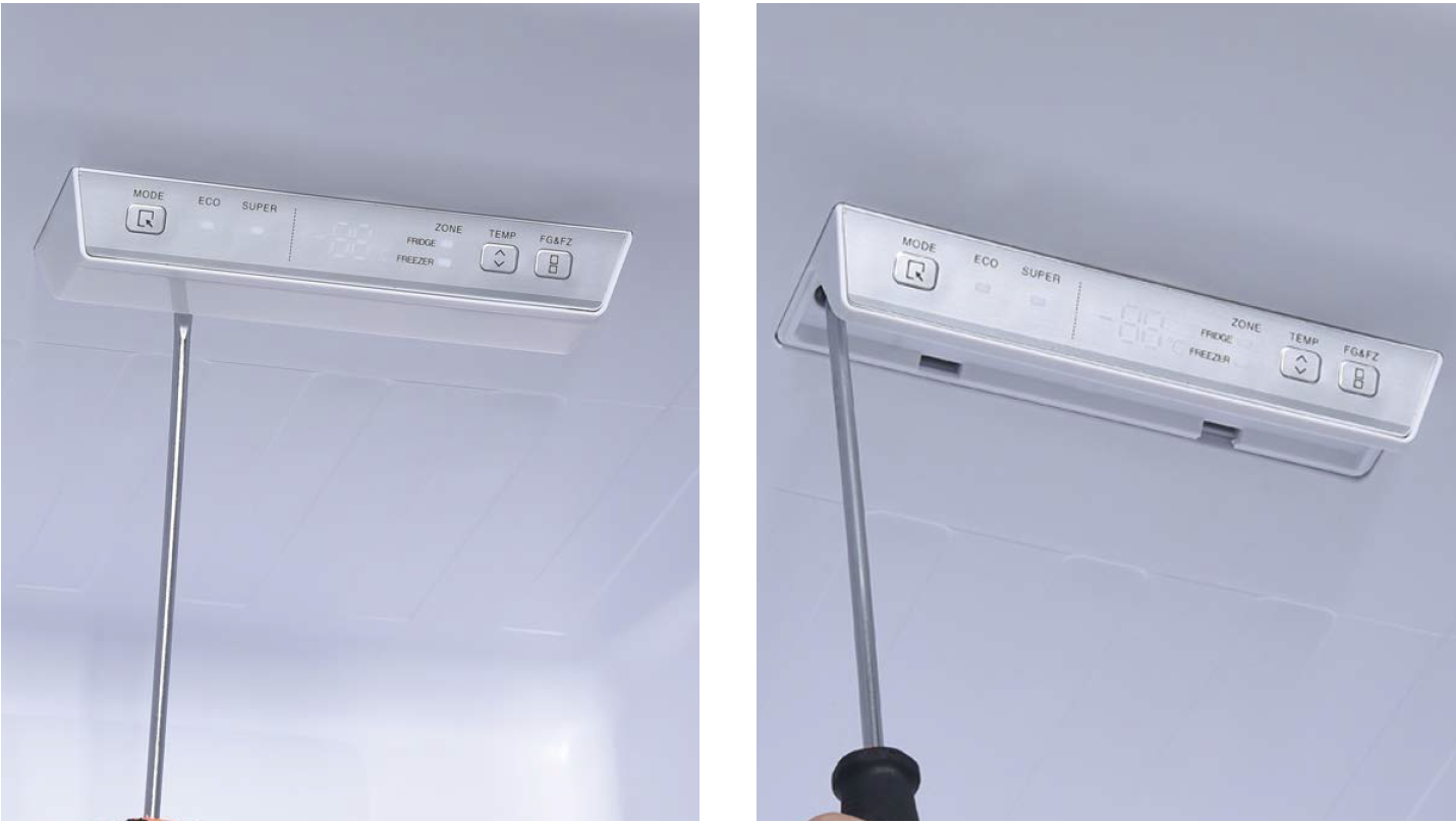
PROCEDURE 3
Step 1
Prize off the cover on door cap.
Step 2
Remove the screws (in total 2).
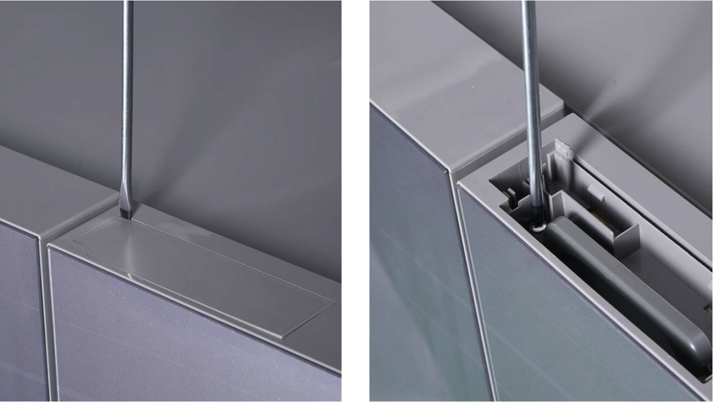
Step 3
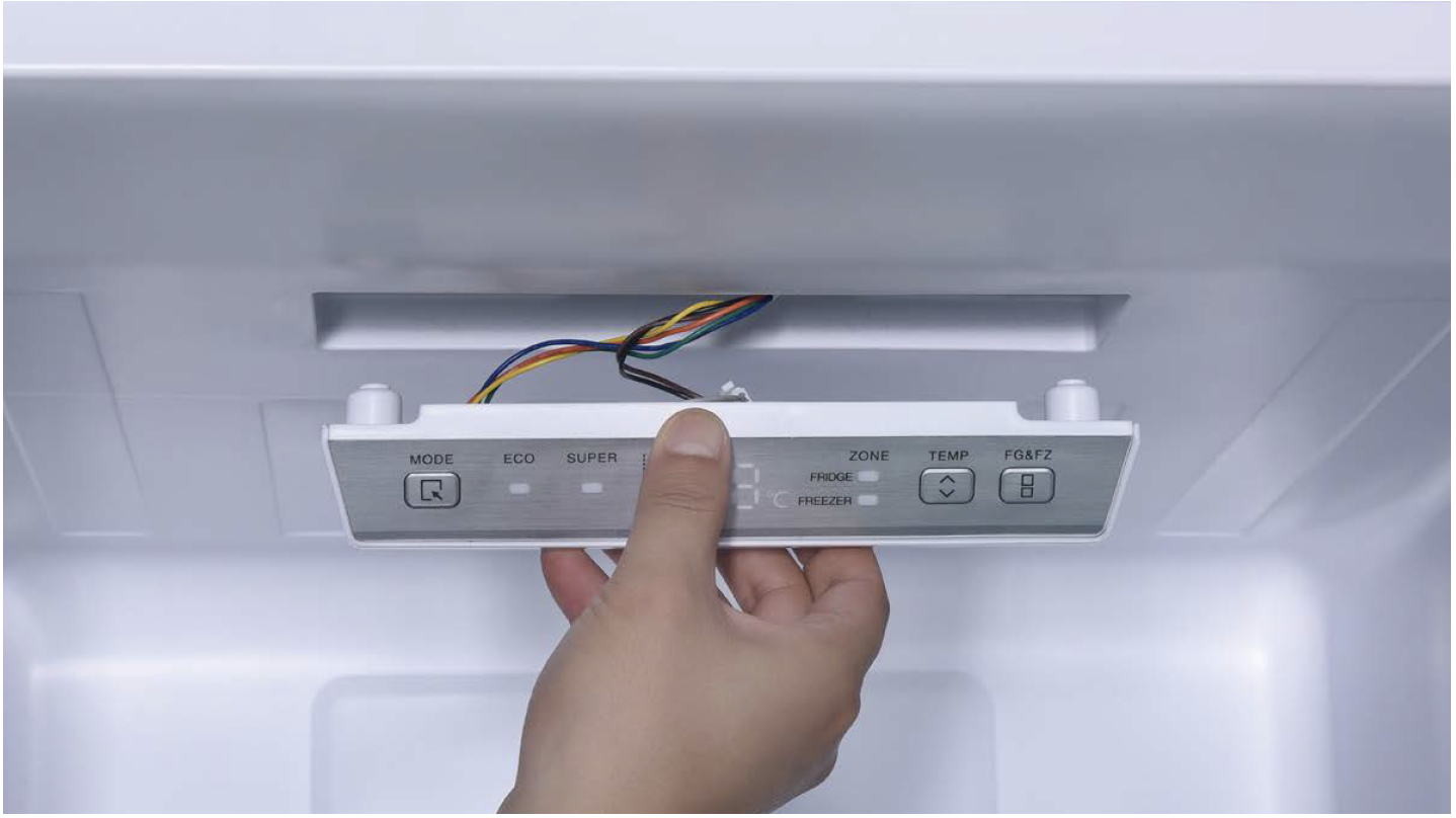
Pull out the plastic.
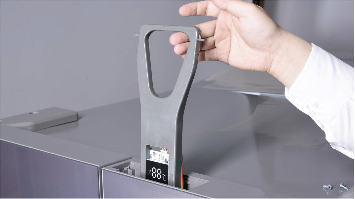
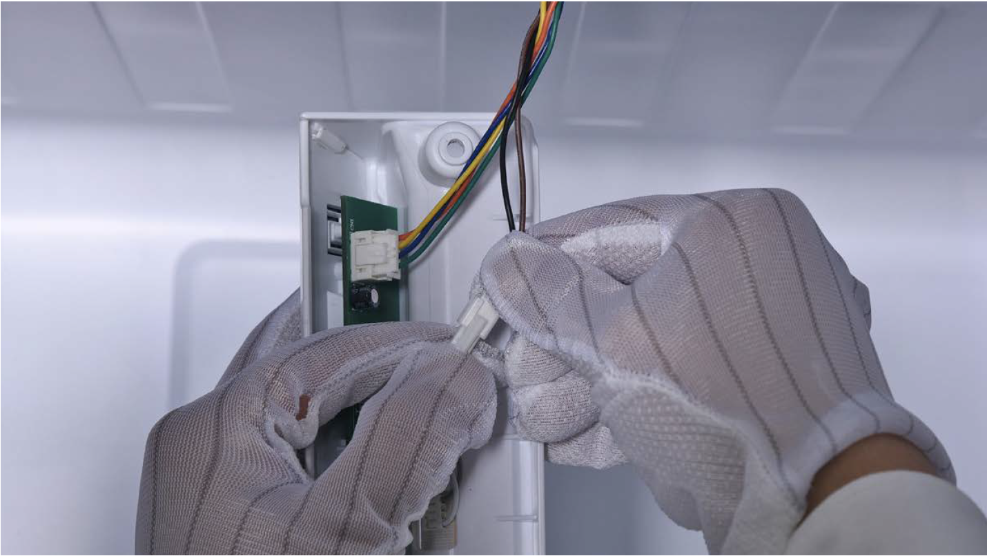
Step 4
Disconnect the terminal for display panel.
Step 5
Remove tape.
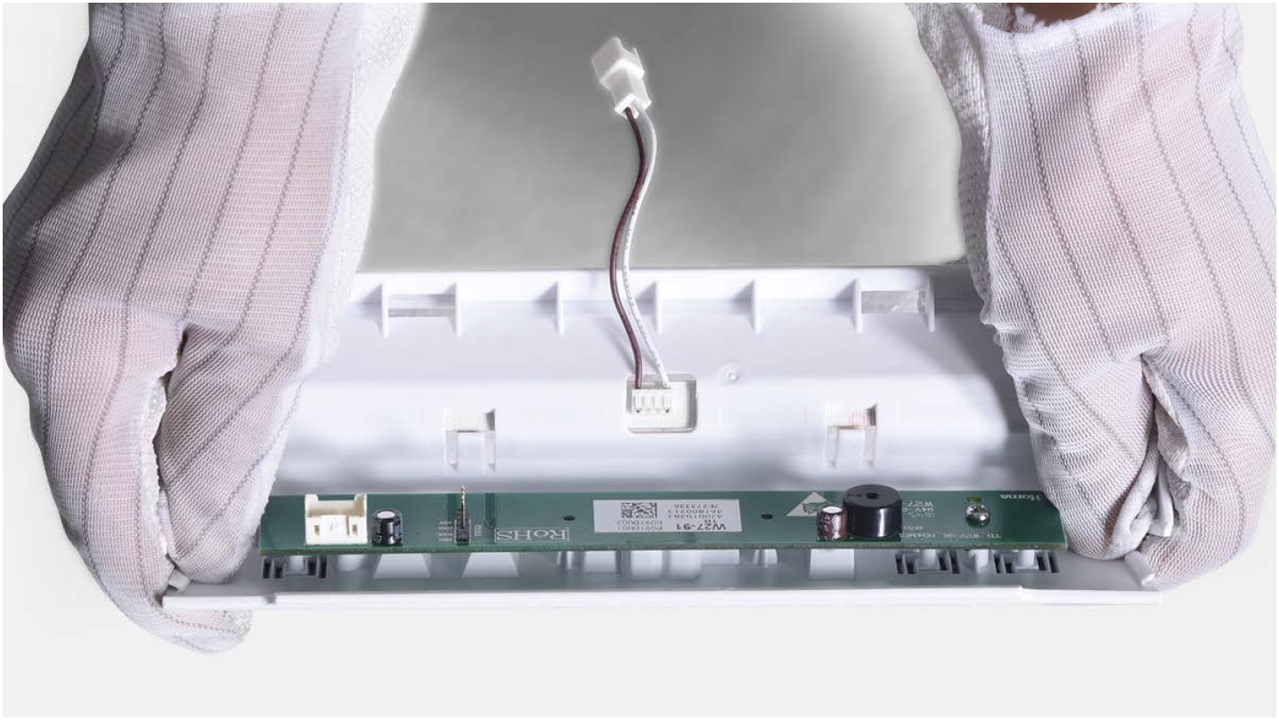
Step 6
Push the display away from the corner.
Reverse steps above
to install display
board.
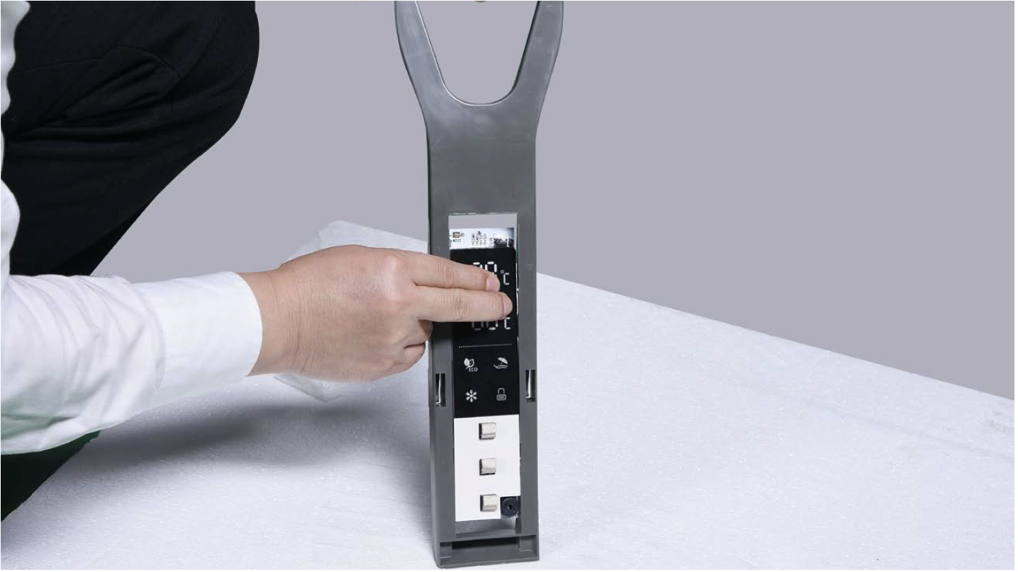
Follow tips carefully:
Tip 1
Please press all buttons on display board to check if it works well or not. Make sure words and icons are clear.

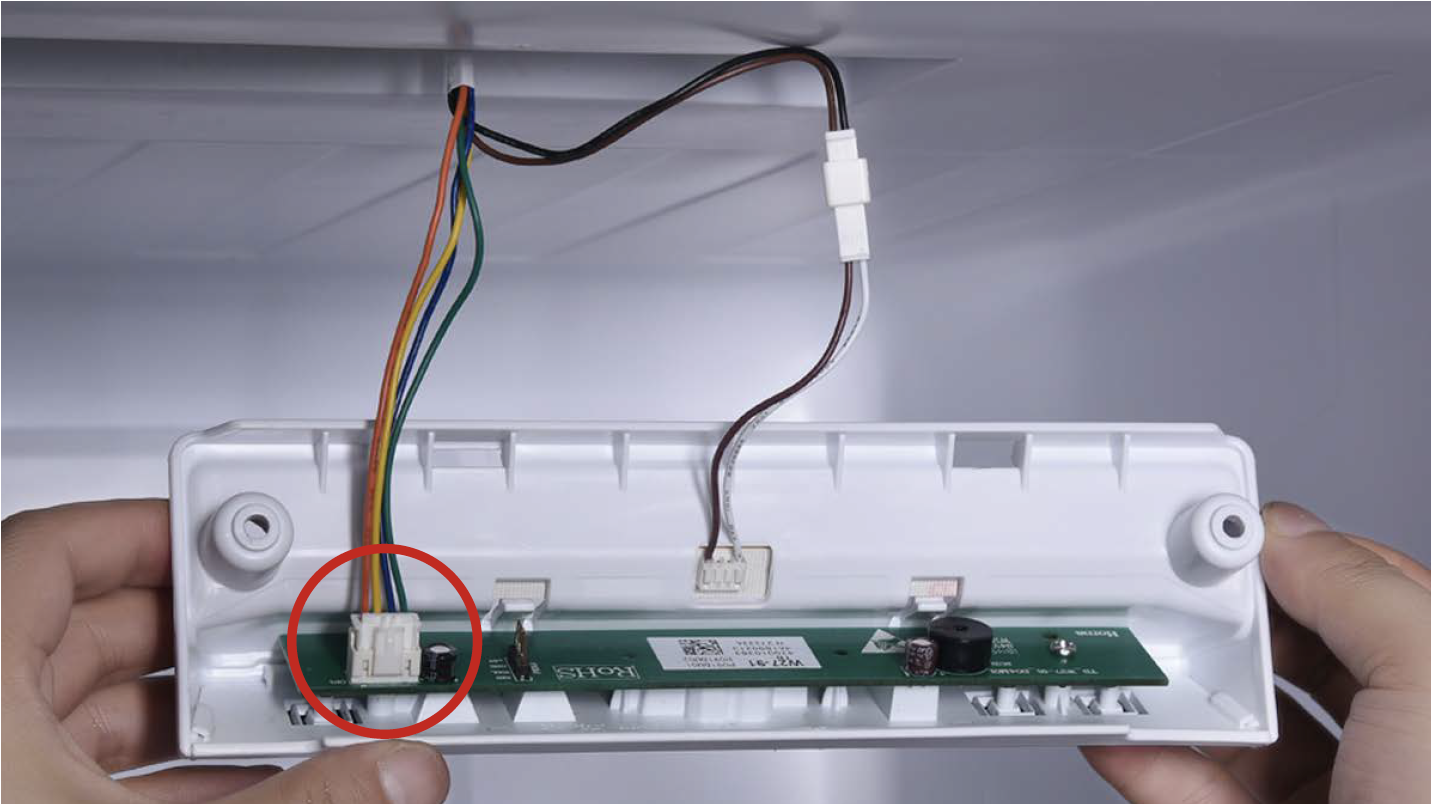
Tip 2
If not, disassemble it and put tape onto the point indicated by red circle.

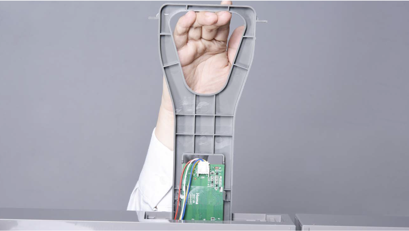
PROCEDURE 4
Step 1
Use a slotted driver to prize off from back of cover.
Step 2
Unscrew with 6mm Cross-head screwdriver.
Step 3
Pull down the lamp box.
Step 4
Disconnect the terminals for LED and for control board.
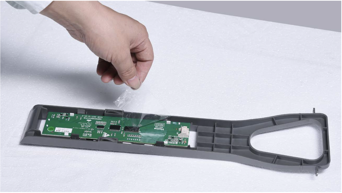
Step 5
Loosen the clips and take off the control panel.
Step 6
Unscrew with 6mm Philips screwdriver and move away the control board.
Reverse steps above to install internal display. Please note below point:
Tip 1
Pay attention to wires while installing the internal display, to avoid damaging with screw.
CHECK AND TEST 4
Step 1
Check if connection and
wire order in display area
are correct or not.
CASE 1: OUTSIDE DISPLAY
CASE 2: INTERNAL DISPLAY
DIAGNOSIS 4

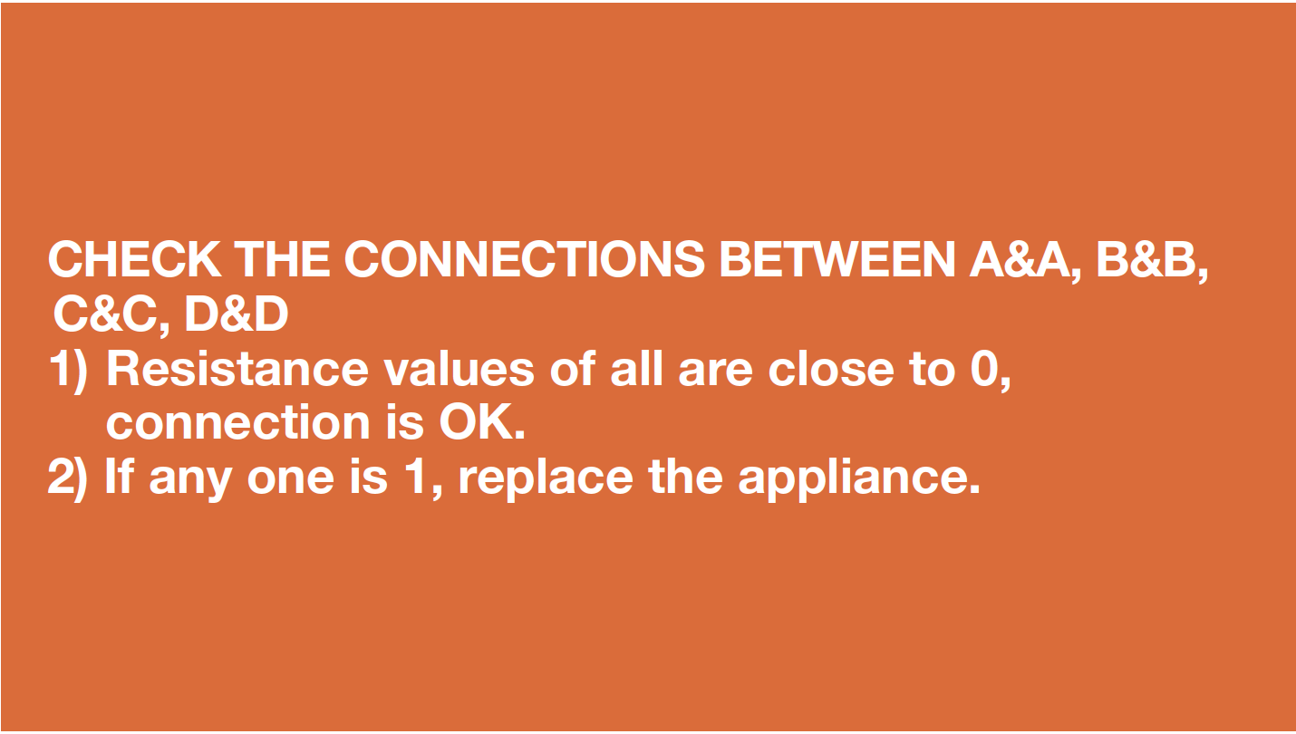
CHECK AND TEST 5
Step 1
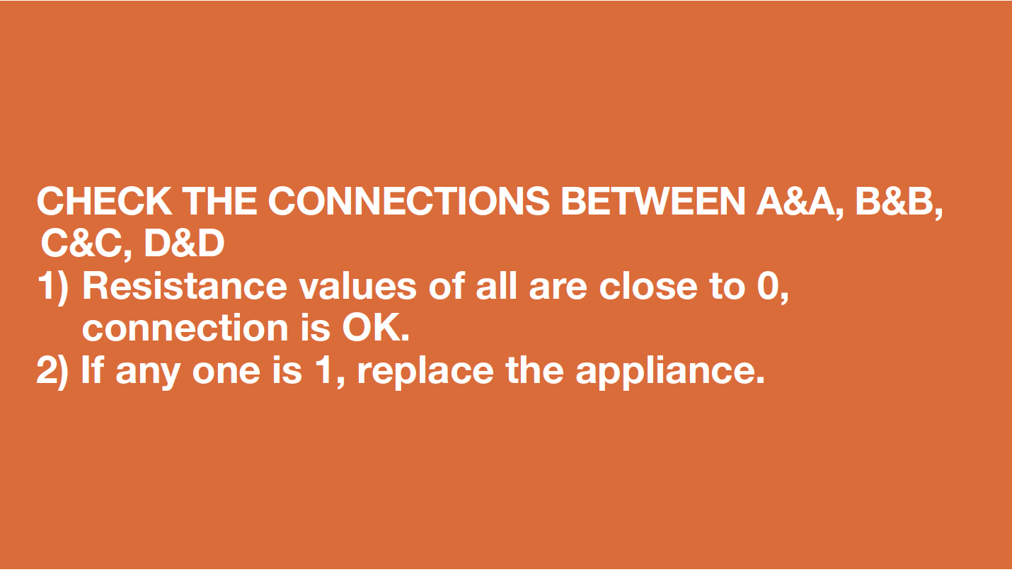
Set multimeter to resistance gear.

CASE 1: OUTSIDE DISPLAY
Step 2
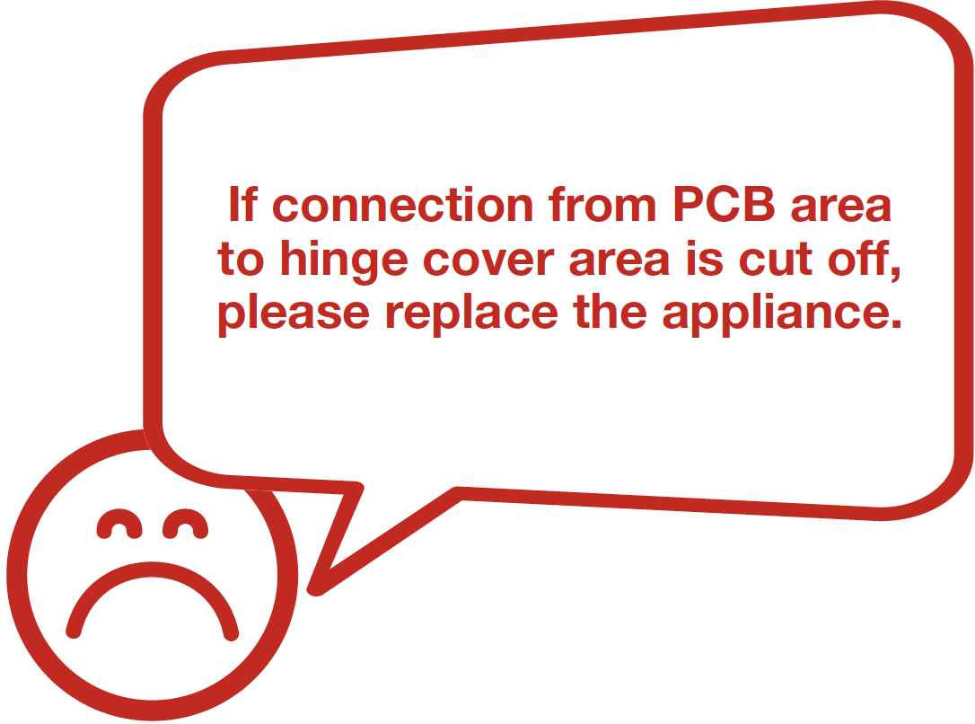
Check wire connection from PCB area to hinge cover area.

Step 3
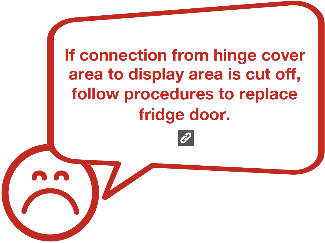
Check wire connection from hinge cover area to display area.
DIAGNOSIS 5
CASE 2: INTERNAL DISPLAY
Step 2
Check wire connection from PCB area to display area.

DIAGNOSIS 5
PROCEDURE 5
Step 1
Unscrew hinge cover.
Step 2
Remove the cover.
Step 3
Disconnect the terminals.

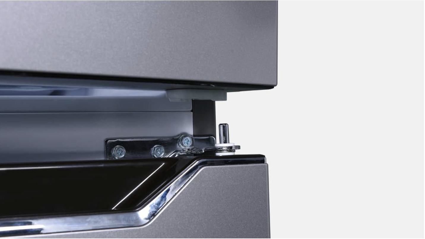
Step 4
Unscrew 3 bolts and remove the top hinge.

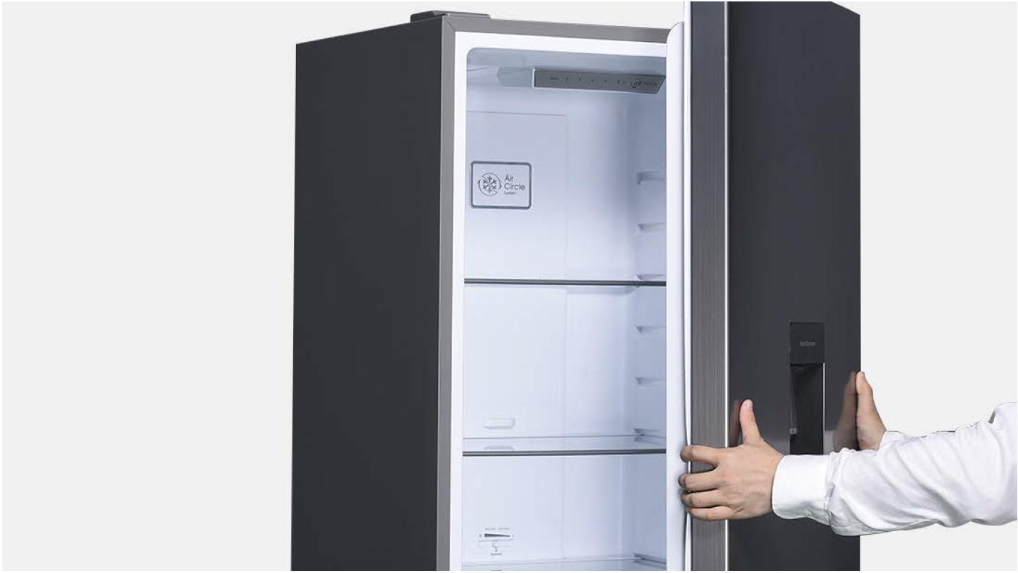
Step 5
Remove upper door.
Reverse procedures above to restore hinges and doors, however, please pay attention to below points:
Tip 1
Don’t forget to add washer onto hinge pin.
Tip 2
When installing door onto hinge, please check the alignment between door-stopper and hinge.
Tip 3
Make sure gasket is attached well.
Tip 4
Make sure gaps between doors are even.
CHECK AND TEST 6

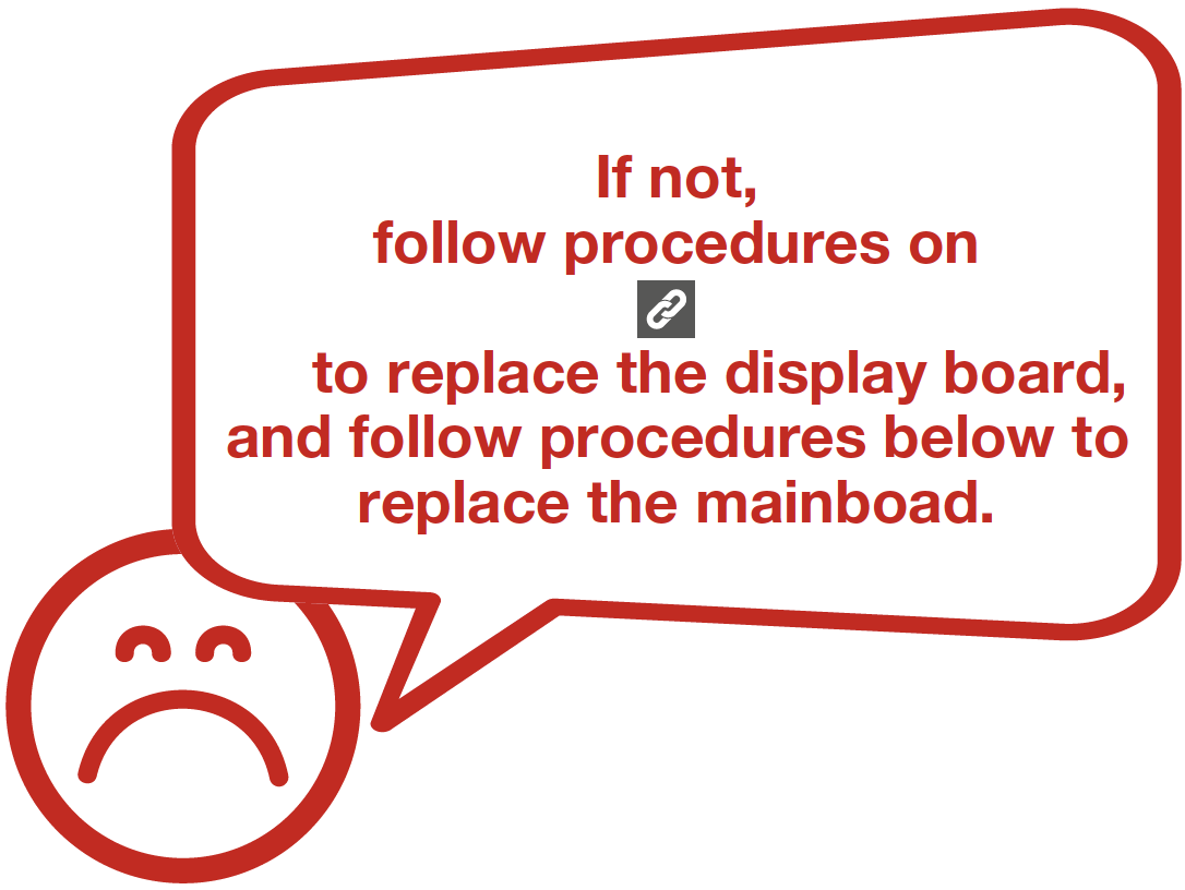
PROCEDURE 6
Step 1
Unscrew cover of mainboard with a cross-head screwdriver.
Step 2
Disconnect terminals.
Step 3
Prize off earthing wires.

Step 4
Unscrew the mainboard
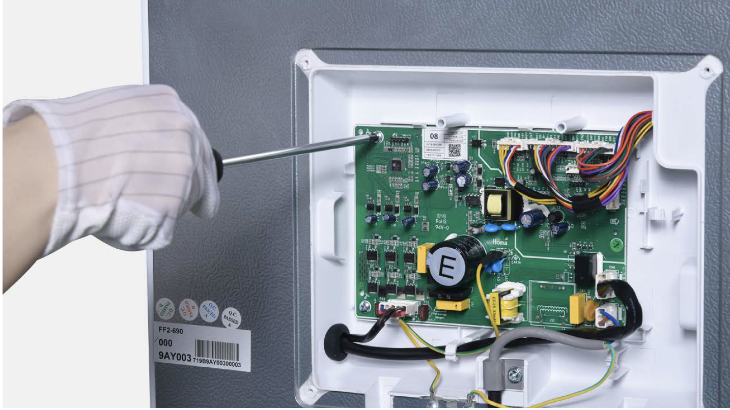
Step 5
Prize off the buckle to remove mainboard.
Reverse steps above to install a new mainboard.
CHECK AND TEST 7


GO BACK TO FAULT LIST RELIABILITY