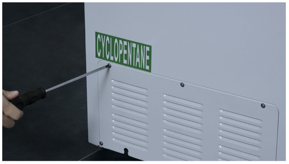
DIAGNOSIS 1

Step 1
Disassemble the compressor room cover.
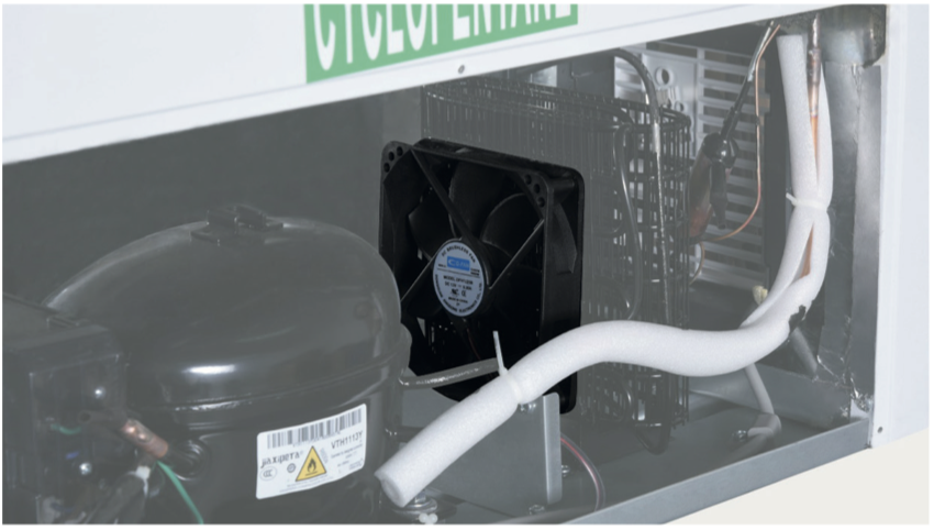
Step 2
Check if the fan blade is blocked or not. If blocked, clear the sundries.

DIAGNOSIS 1


CHECK AND TEST 2
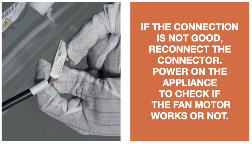
Step 1
Unplug and check if the fan motor wire and connectons are good.
DIAGNOSIS 2

PROCEDURE 1
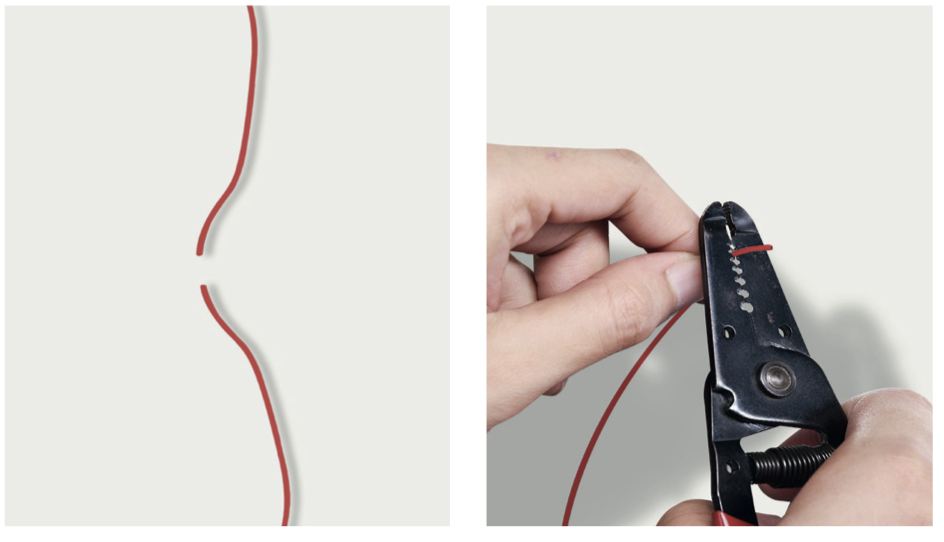
Step 1
Cut wire off.
Step 2
Peel off the sleeves.
Step 3
Check to ensure proper wire order and connect them.

Step 4
Tin soldering
Step 5
Cover connection with electrical tape.

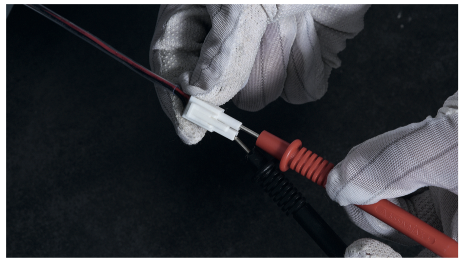
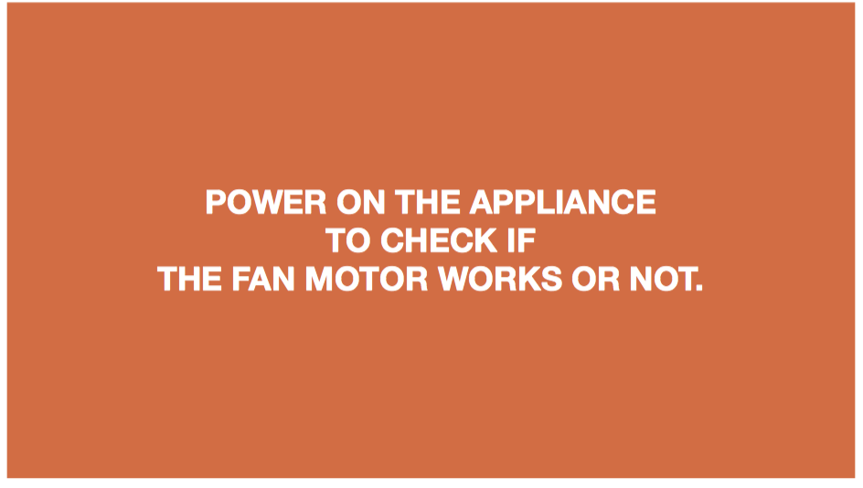
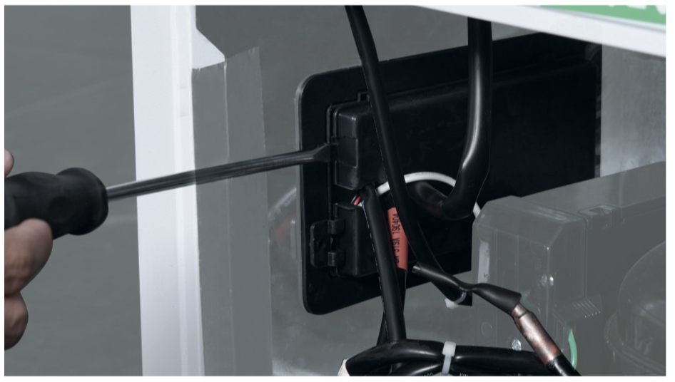
DIAGNOSIS 3


CHECK AND TEST 3
Step 1
Disconnect the fan motor wire connector.

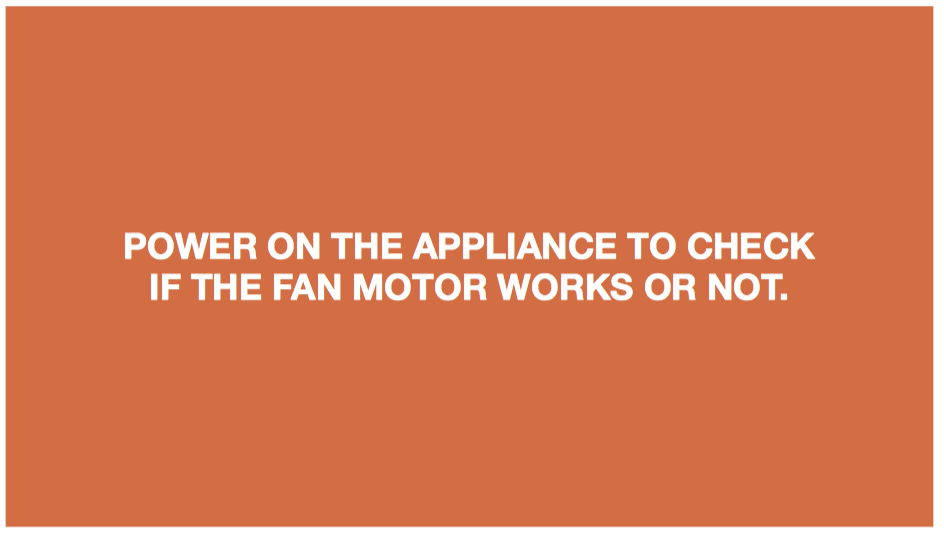
Step 2
Supply 12V DC to the fan motor wire terminals to check if the fan motor works or not.
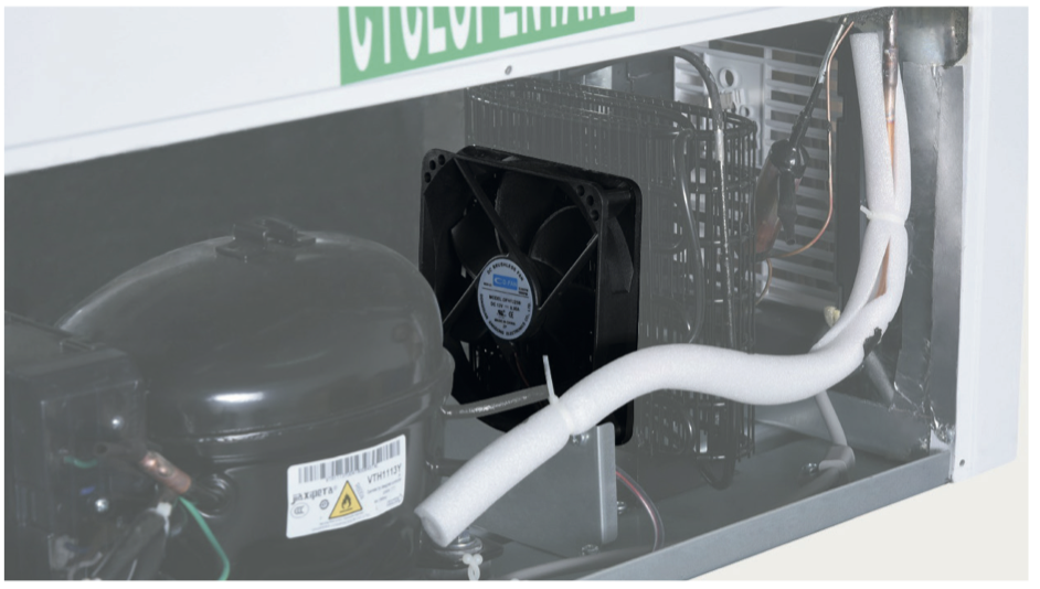
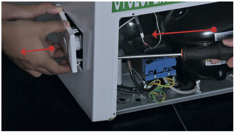
DIAGNOSIS 4

PROCEDURE 2
Step 1
Unscrew the screws of fan motor.

Step 2
Take out the fan motor along with the fan motor bracket.
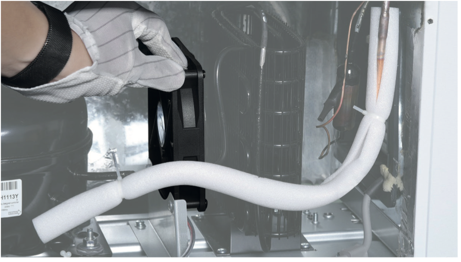
Step 3
Reverse above steps to install a new fan motor.
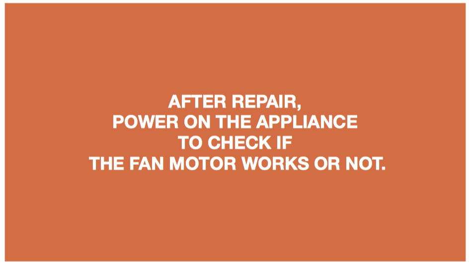
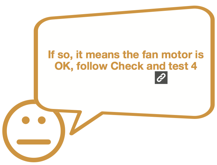
DIAGNOSIS 5


CHECK AND TEST 4
Step 1
Unscrew the screw of PCB cover.

Step 2
Remove the PCB cover.
Step 3
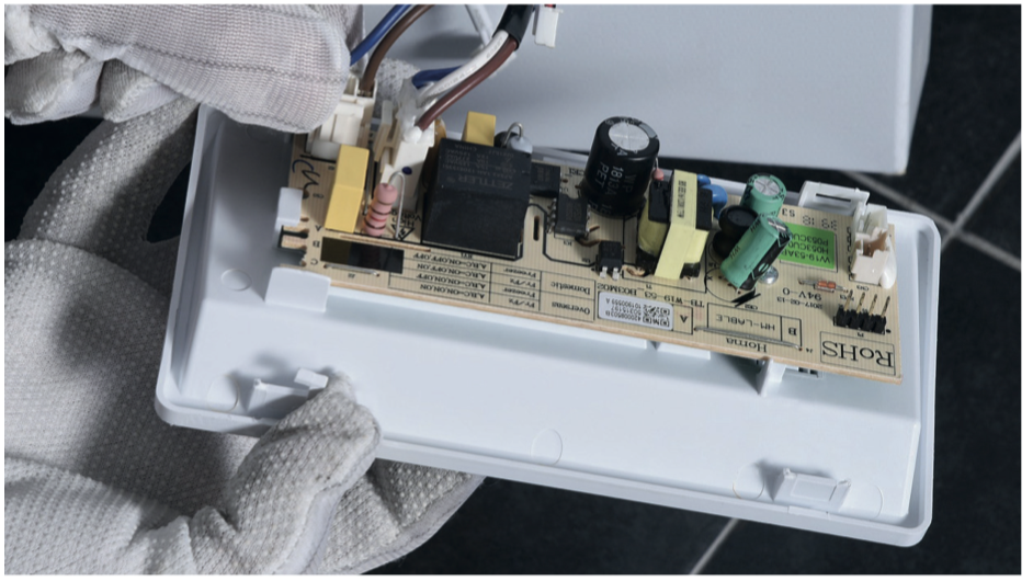
Push the PCB box out to disassemble the PCB along with the PCB box.
Attention: do not damage the PCB when pushing the PCB control panel box out
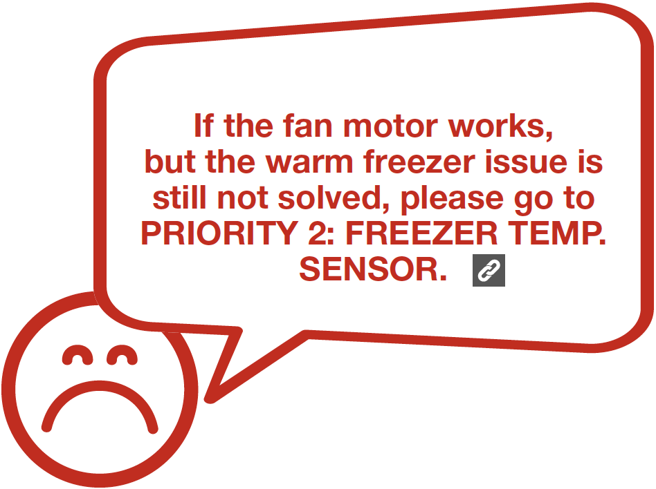
DIAGNOSIS 6


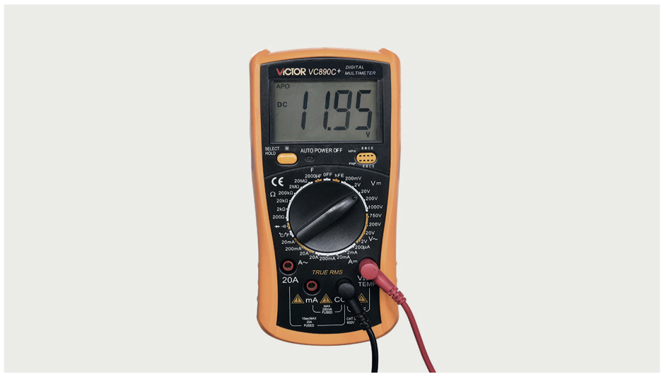
CHECK AND TEST 5
Step 1
Power on and use multimeter to test the voltage of output for fan.

Step 2
Record the test result.
DIAGNOSIS 7

PROCEDURE 3
Step 1
Disconnect all the connectors in the PCB area.
Step 2
Replace with a new PCB board and control panel box.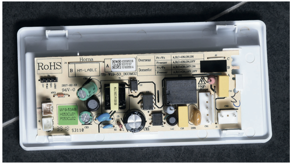
Step 3
Reverse steps above to reconnect the terminals.
DIAGNOSIS 8
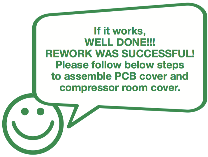
PROCEDURE 4
Step 1
Install back the control panel.

Step 2
Screw the screw of PCB cover.
Step 3
Screw the screw of compressor room cover.