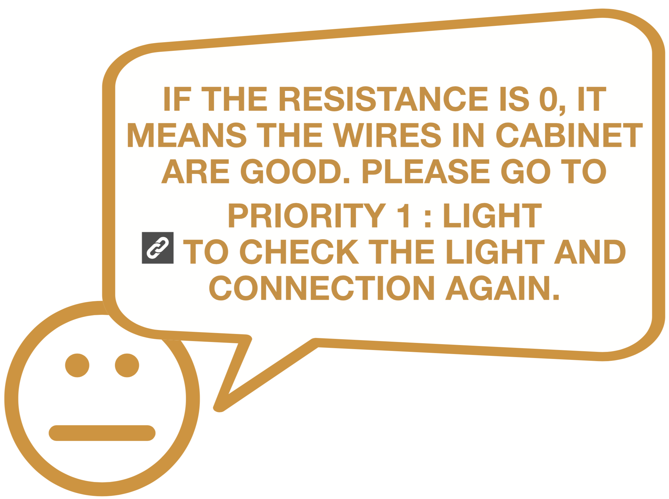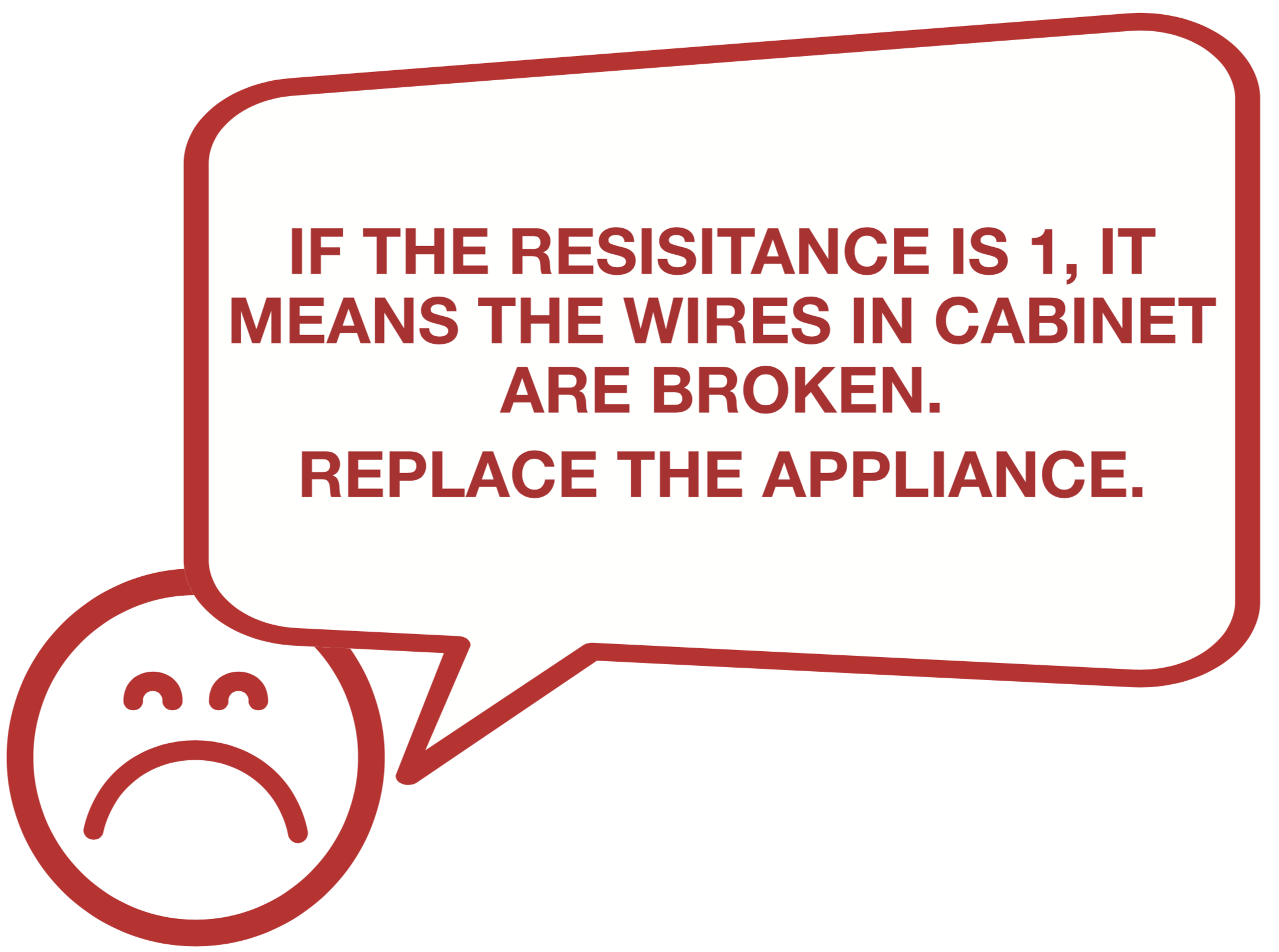

CHECK AND TEST 1
Step 1
Disassemble the compressor room cover.
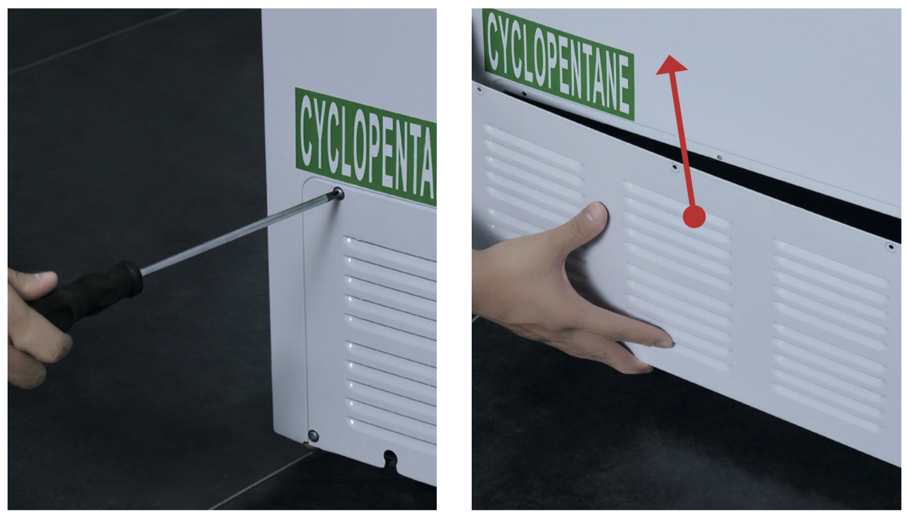
Step 2
Unscrew the screw of PCB cover.
Step 3
Remove the PCB cover.
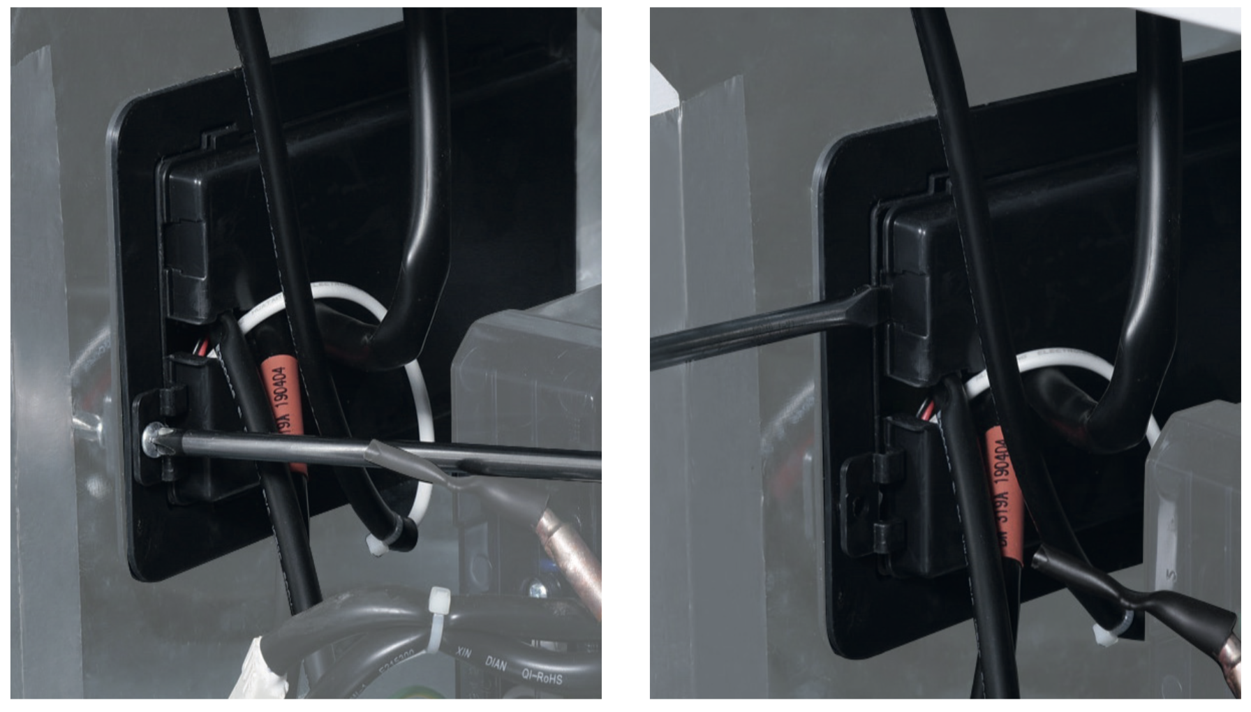
Step 4
Push the PCB box out to disassemble the PCB along with the PCB box.
Attention: do not damage the PCB when pushing the PCB control panel box out.
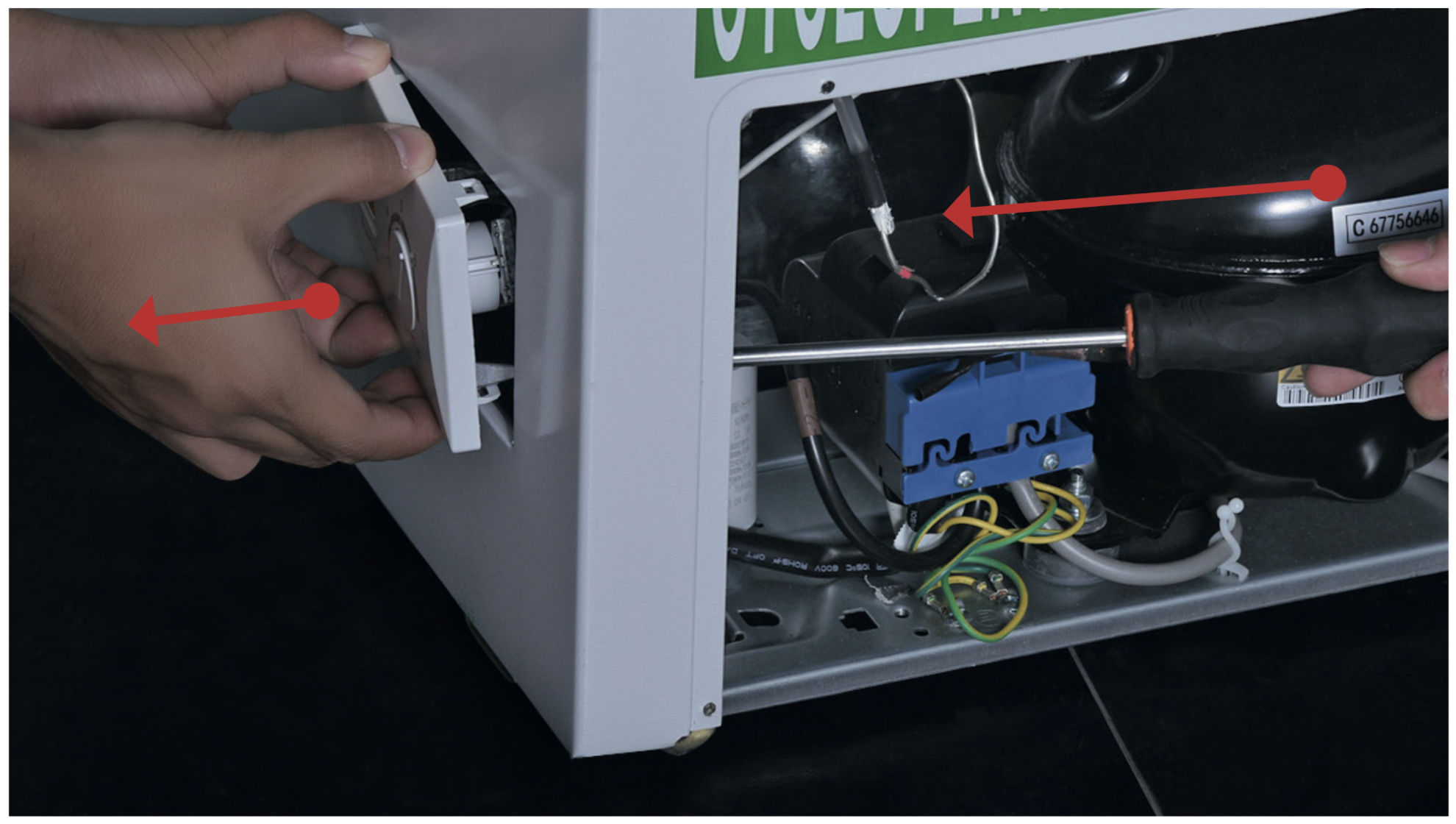
Step 5
Check if the terminal is loose.
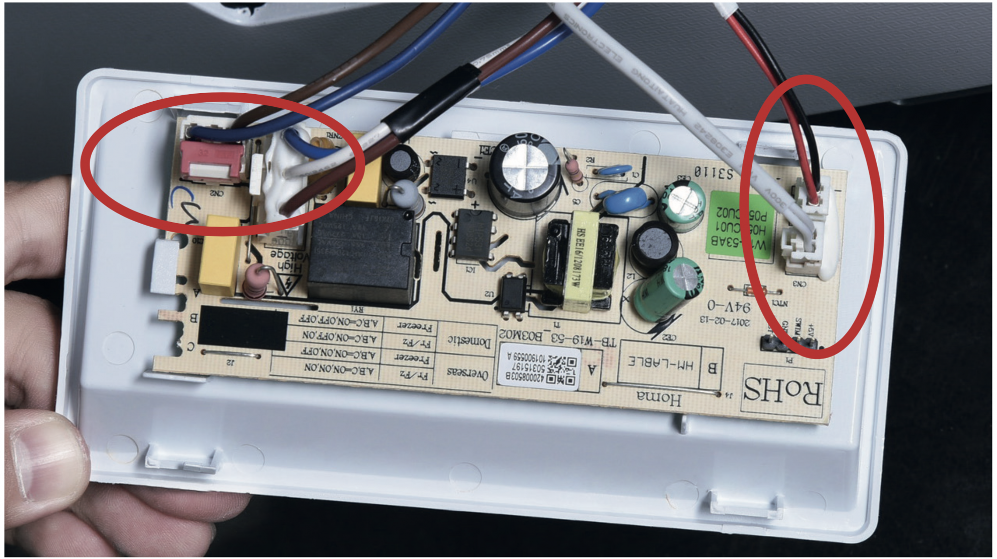
DIAGNOSIS 1
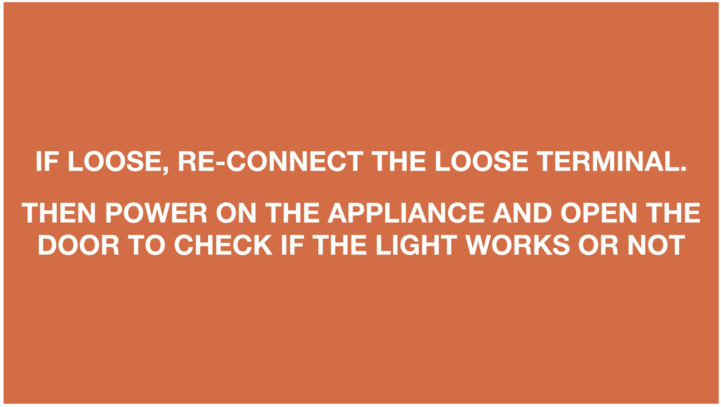

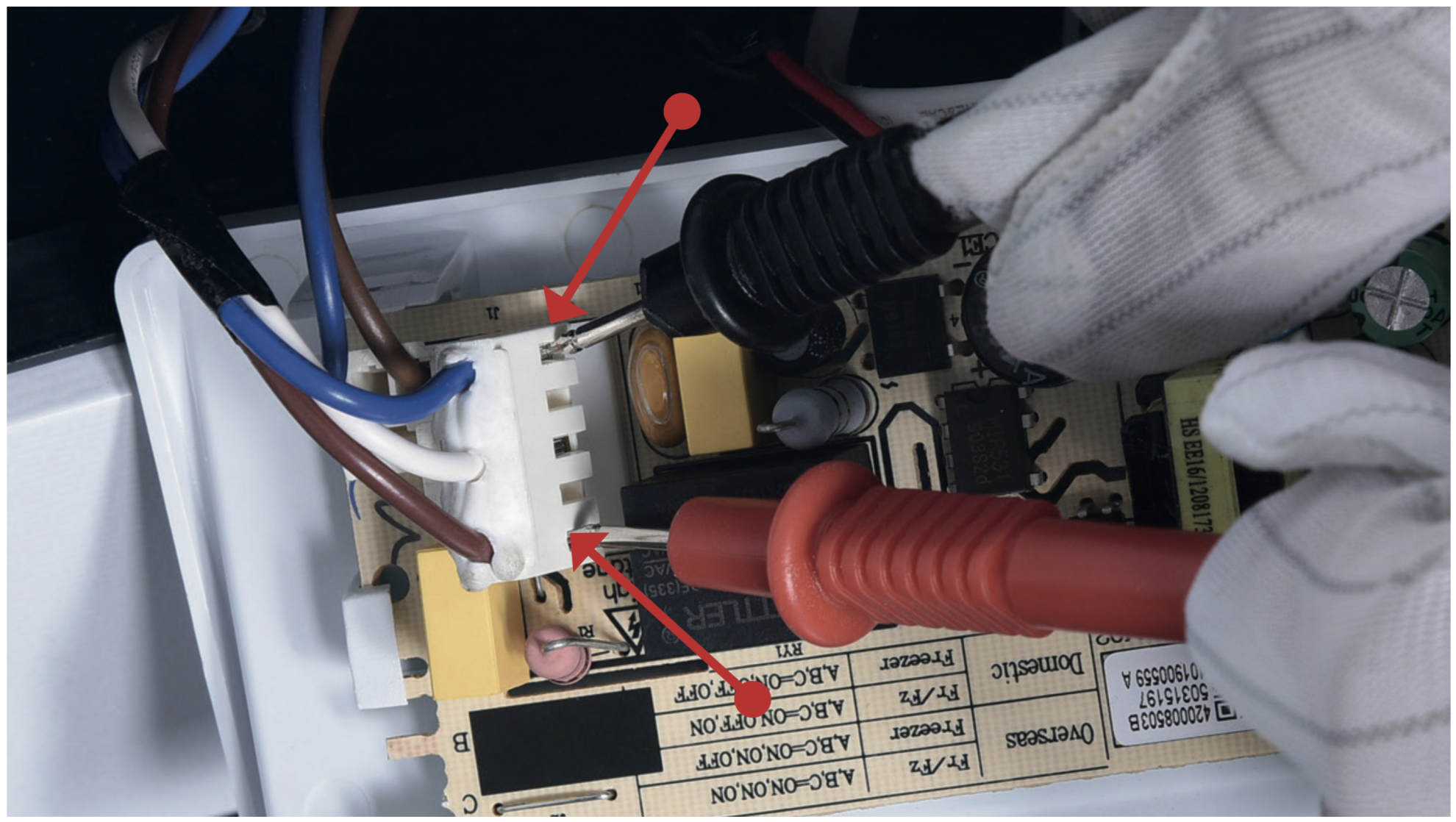
Step 1
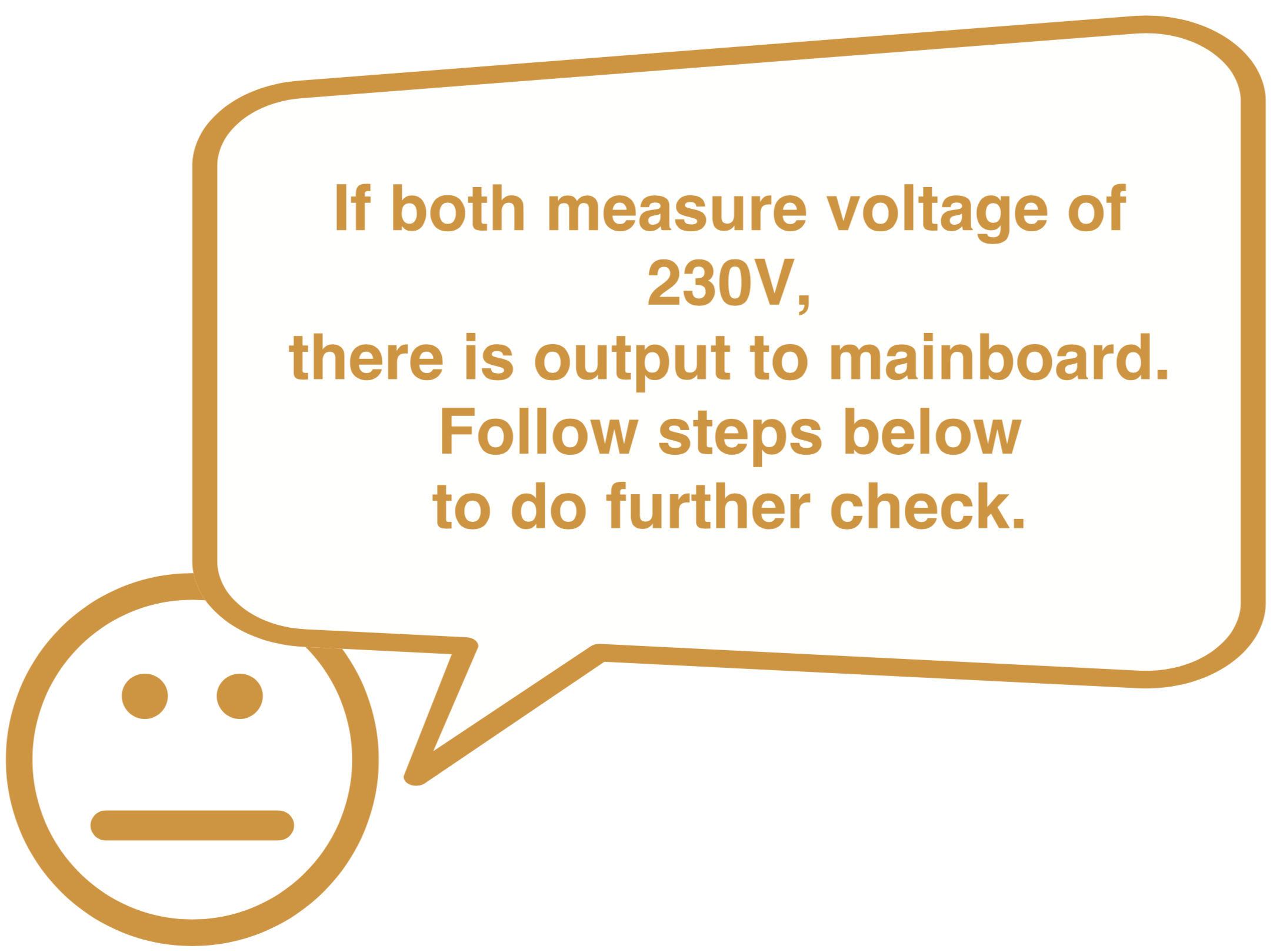
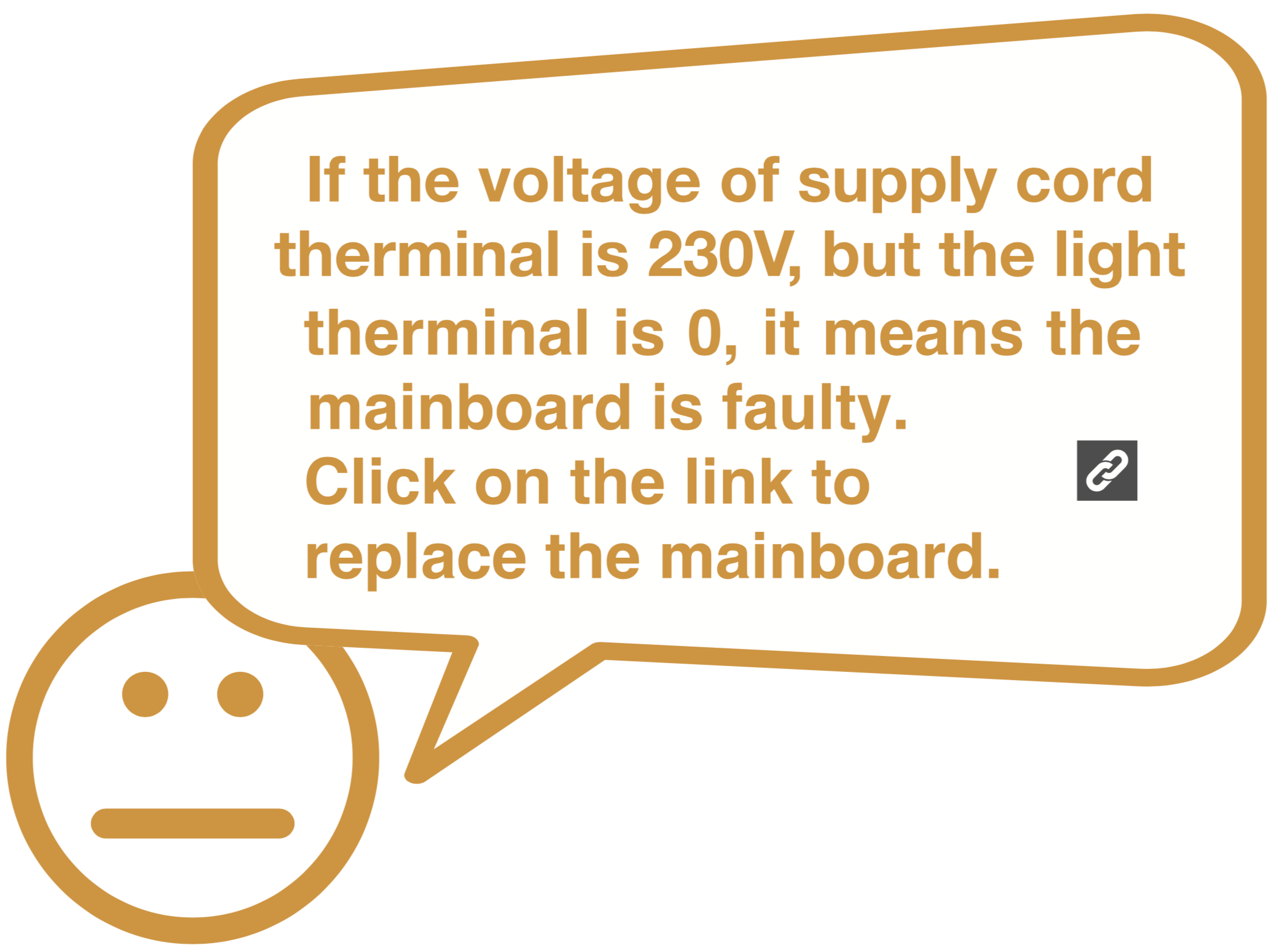
Measure the output of supply cord terminal.
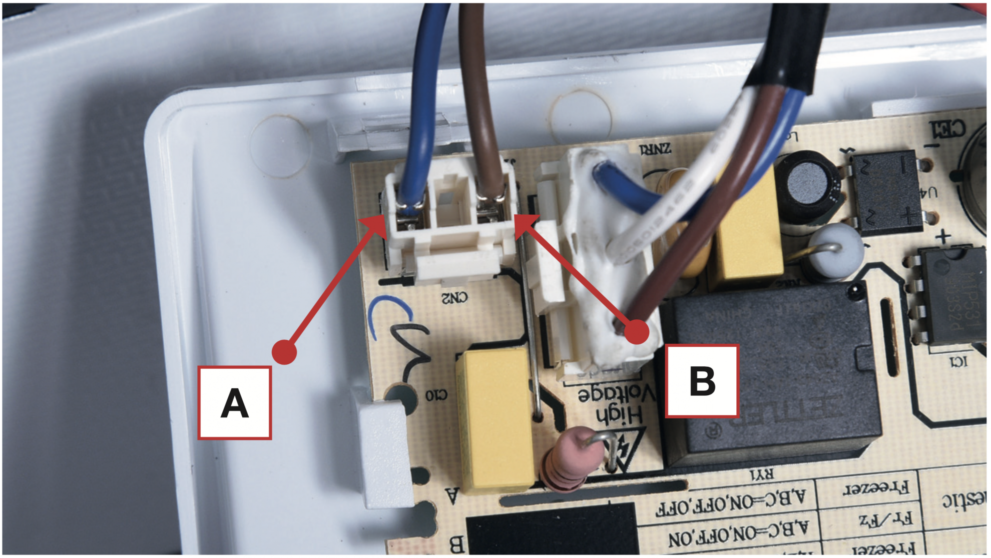
Step 2
Measure the output of of light therminal.
DIAGNOSIS 2


Step 1
Use a wire to connect the A & B terminal.
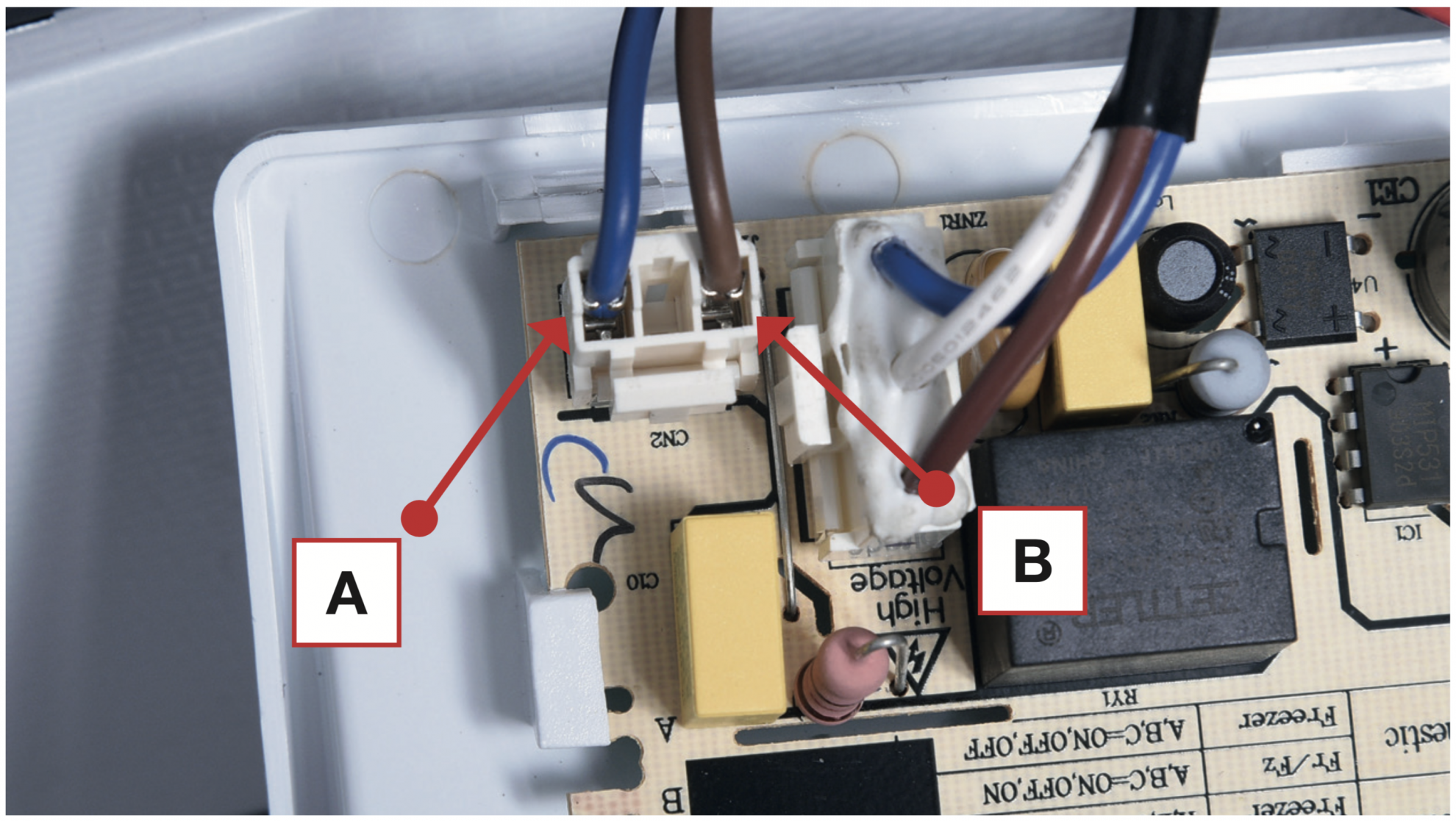
Step 2
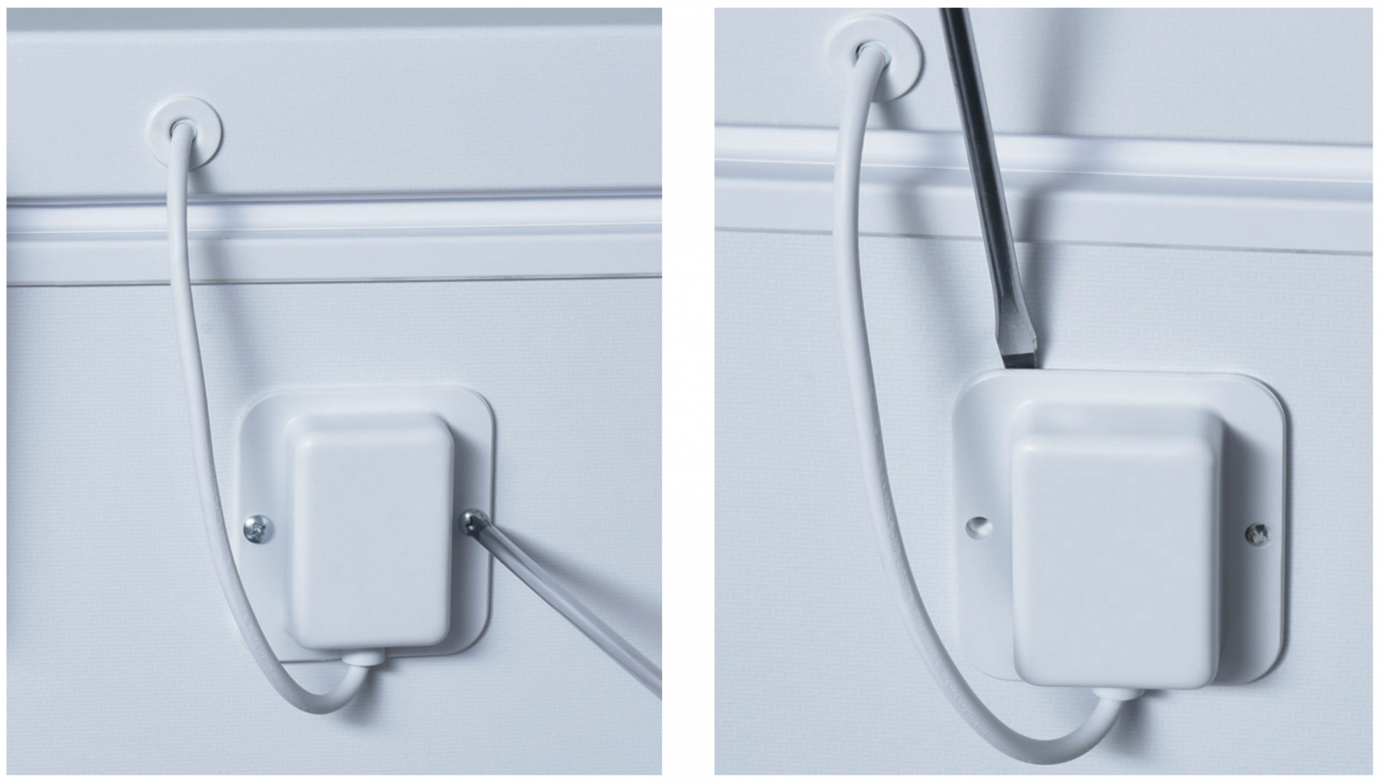
Unscrew the screws on the rear light wire connector cover.
Step 3
Prize up to remove the light wire connector cover.
Step 4
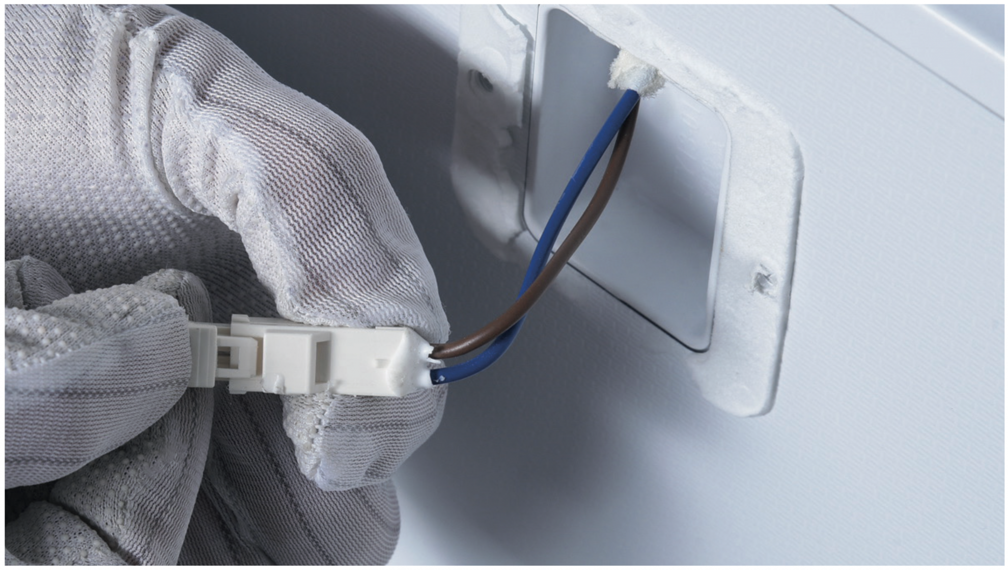
Connect the door light wire.
Step 5
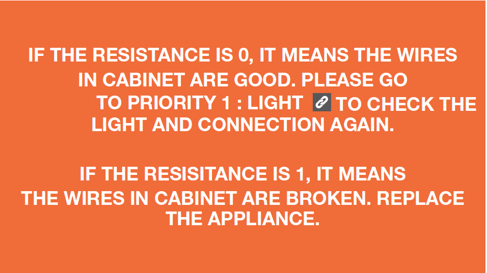
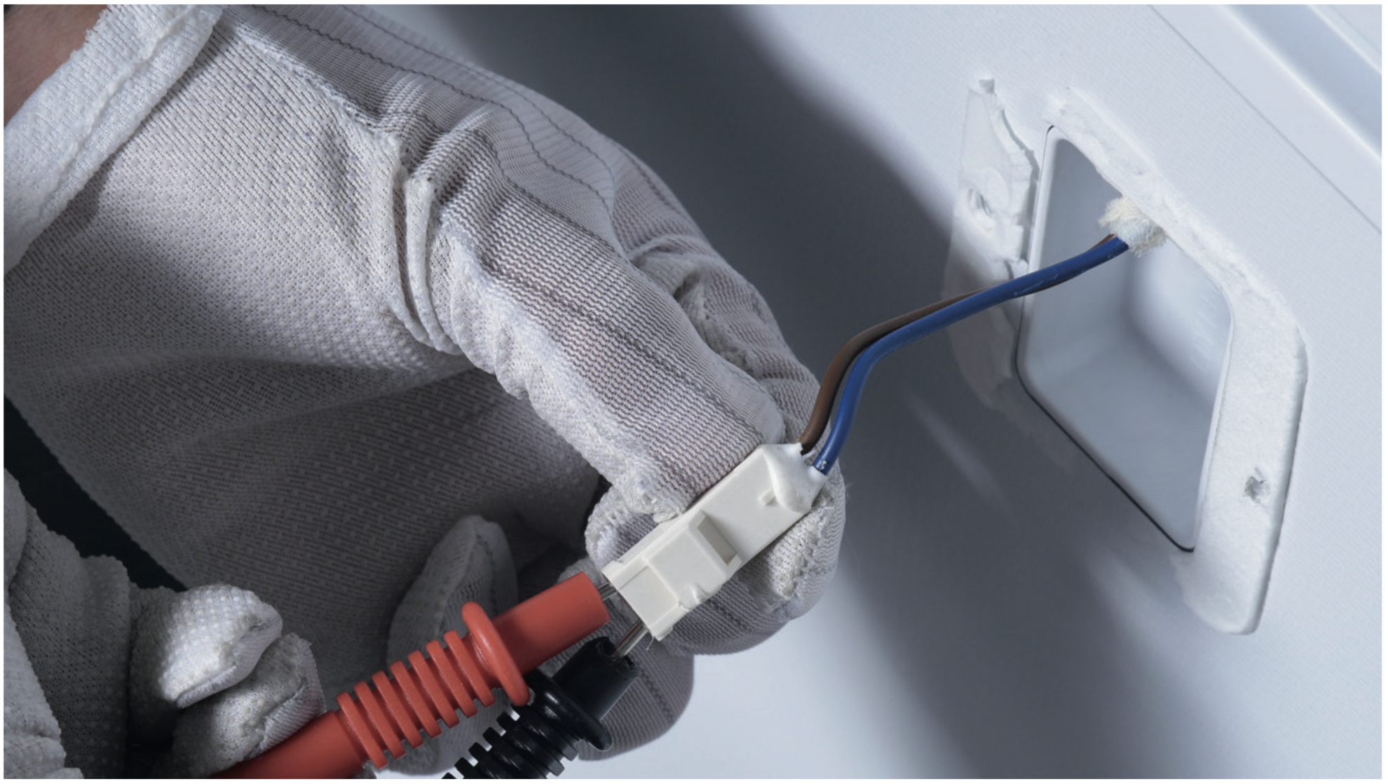
Measure the resistance of the terminals from cabinet side.

Step 1
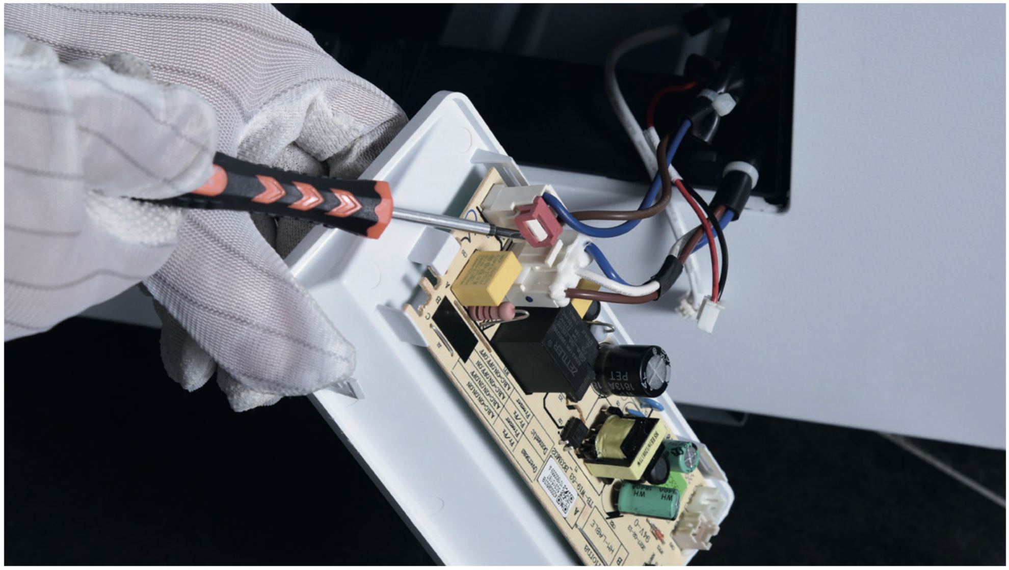
Prize off the buckle and disconnect the terminal.
Step 2
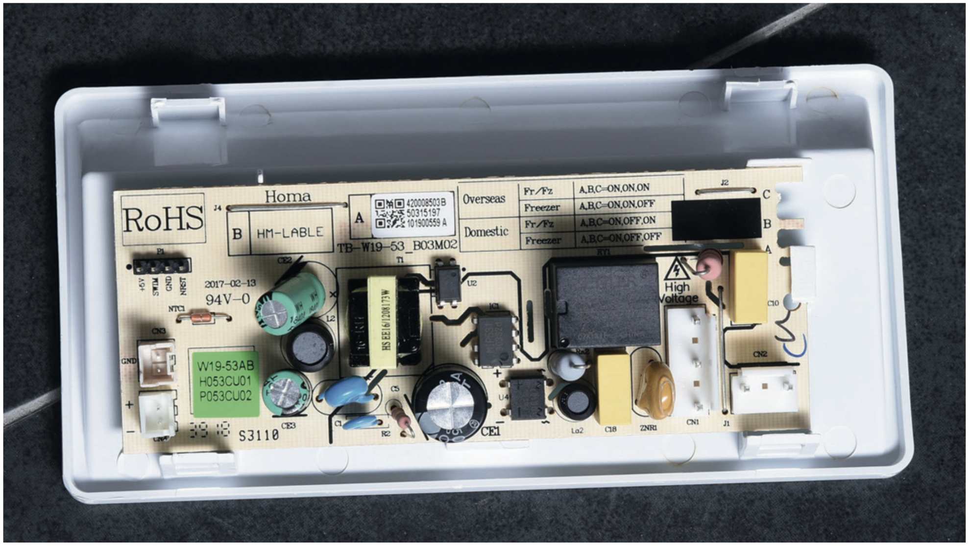
Replace the PCB board as well as the control panel box.
Reverse above steps to install a new PCB and control panel box.

CHECK AND TEST 4
Step 1
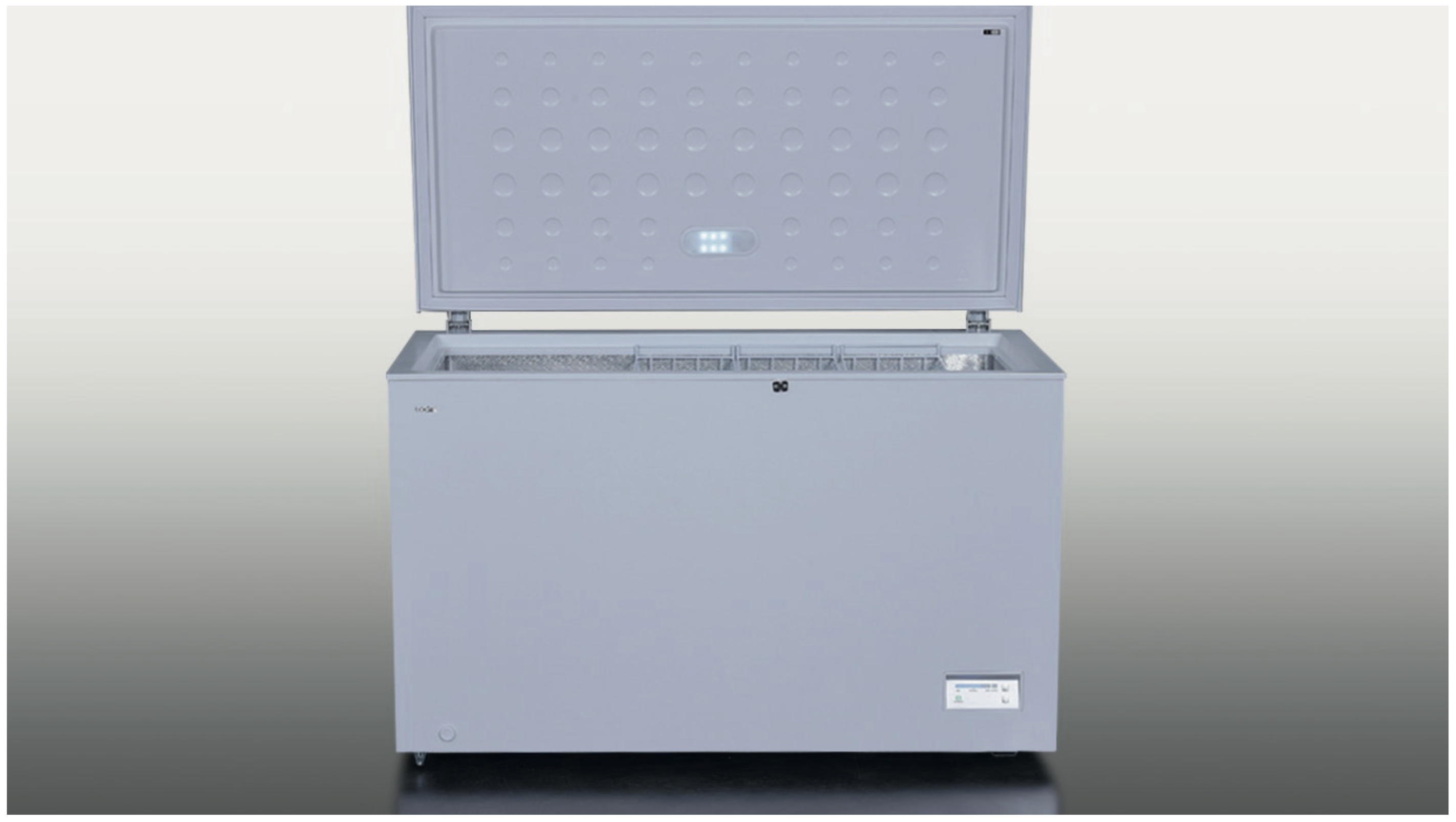
After rework, power on the appliance and open the door.
DIAGNOSIS 4


