

CHECK AND TEST 1
Step 1
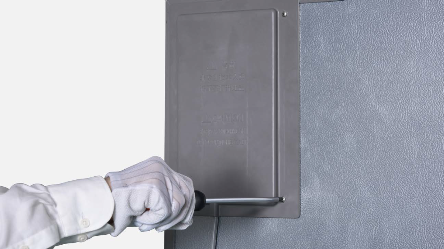
Unscrew cover of
mainboard with a
cross-head screwdriver.
Step 2
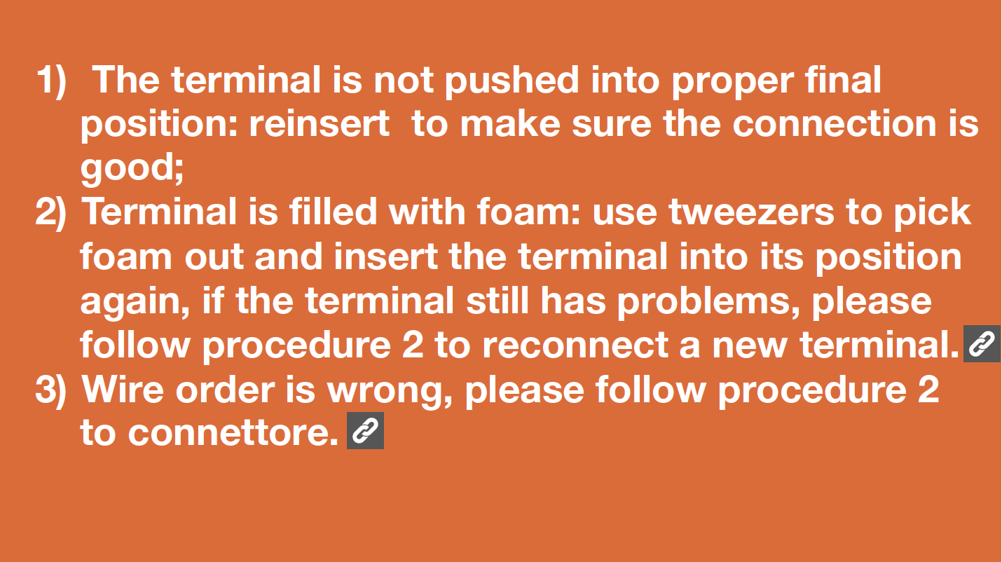
In mainboard area, check if terminal is pushed into proper final position.

Step 3
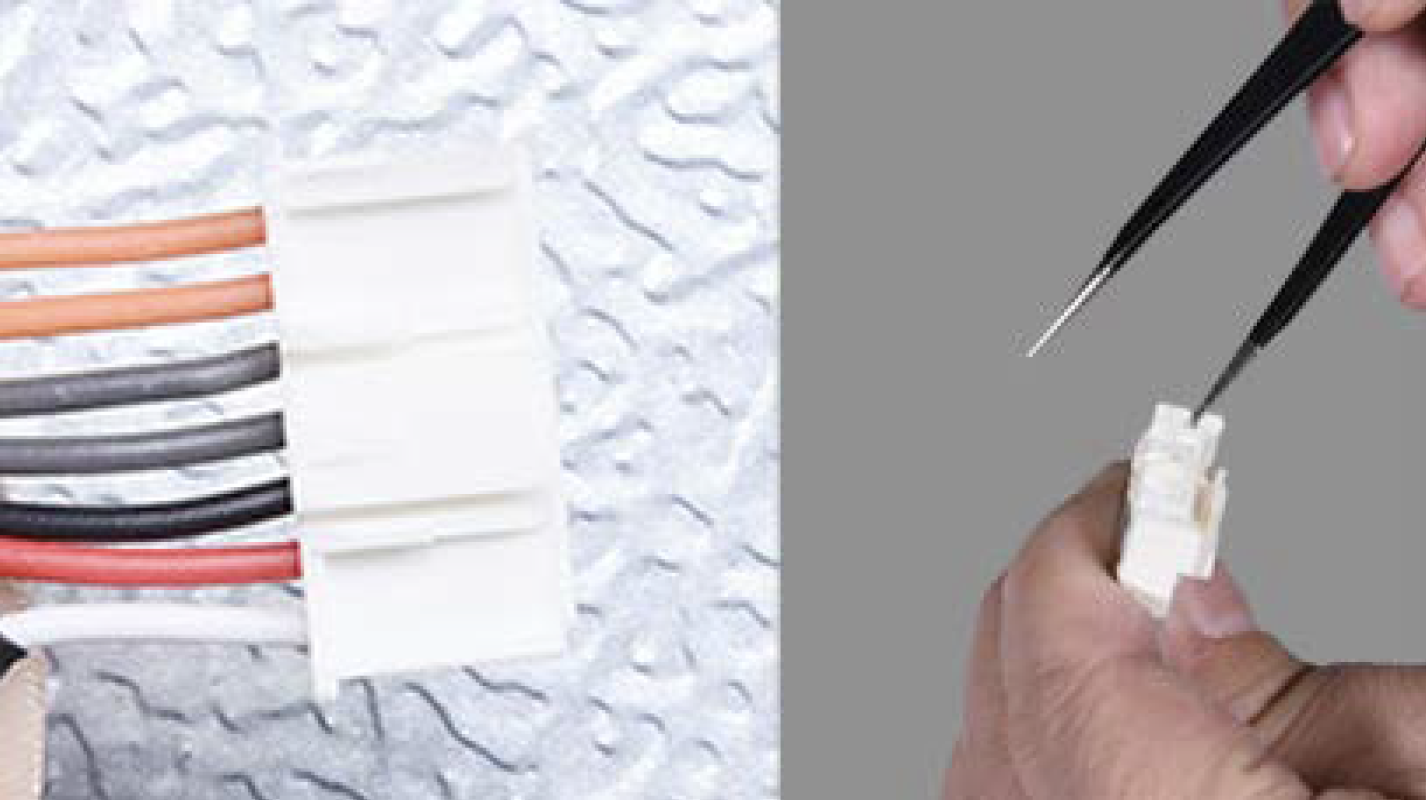
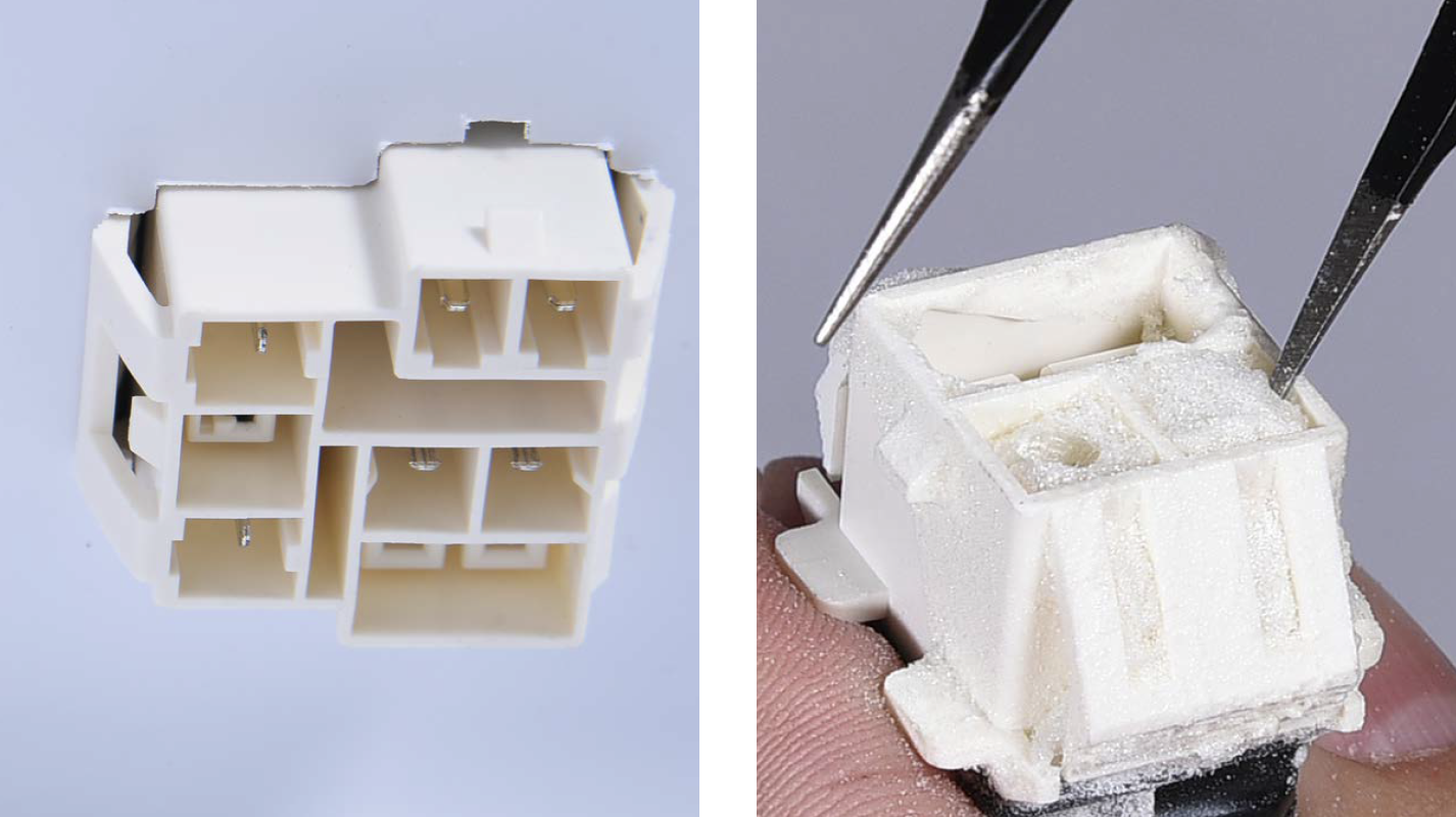
In mainboard area, check if terminal is filled with foam.
Step 4
If so, use tweezers to
remove foam.

DIAGNOSIS 1


CHECK AND TEST 2
Step 1
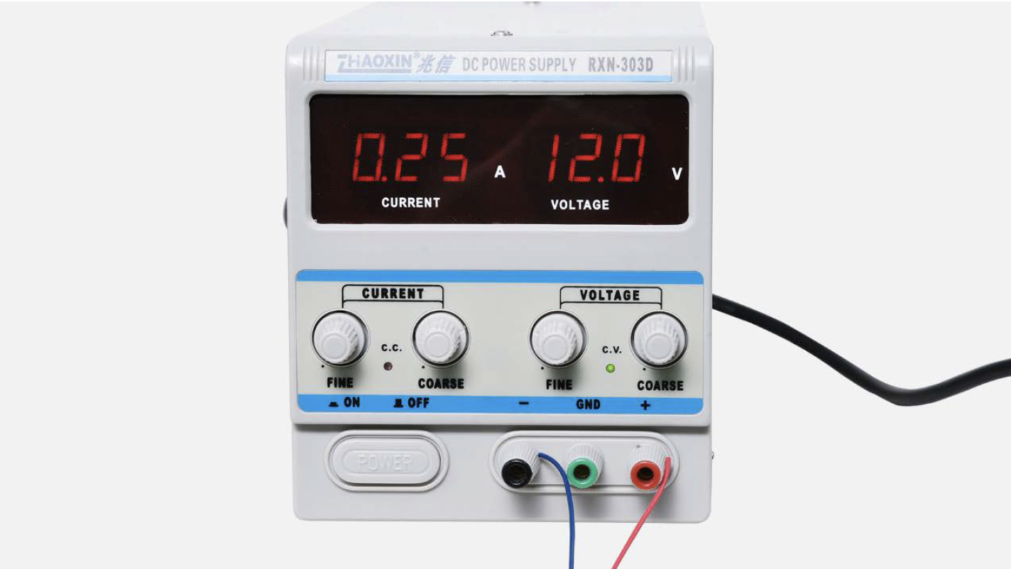
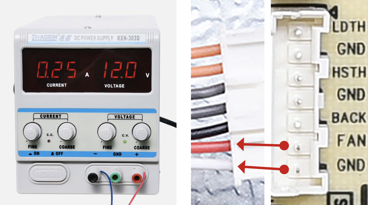
Turn power output of transformer to DC 12V.
Step 2
Supply power from terminal in PCB area (FAN & GND).


DIAGNOSIS 2


PROCEDURE 1
Step 1
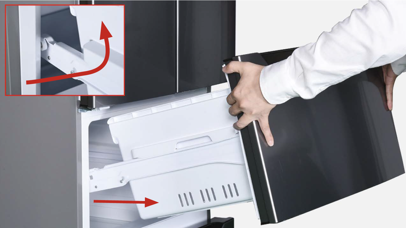
Remove the upper freezer drawer.
Step 2
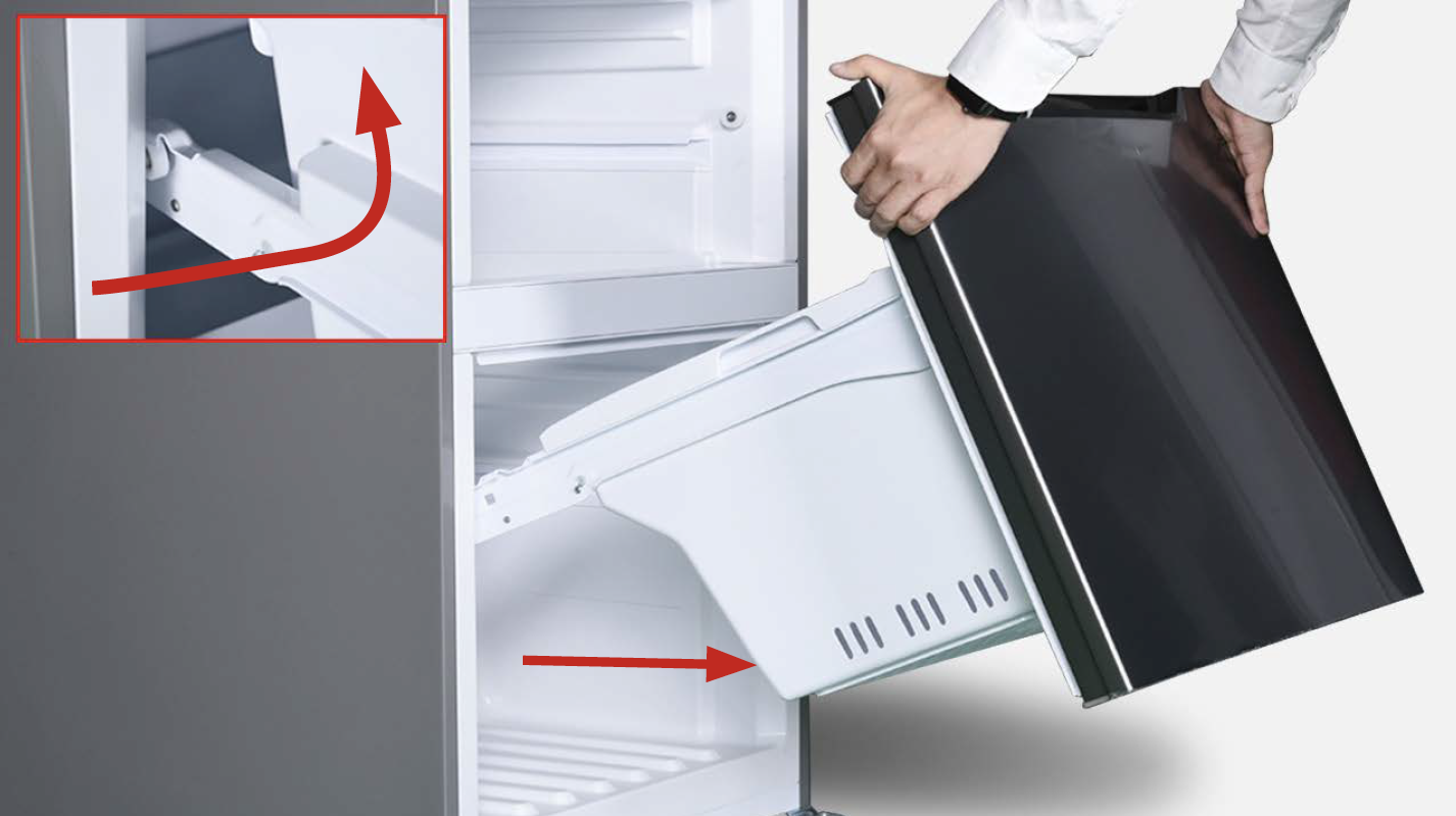
Remove the upper freezer drawer. Remove the upper freezer drawer.
Step 3
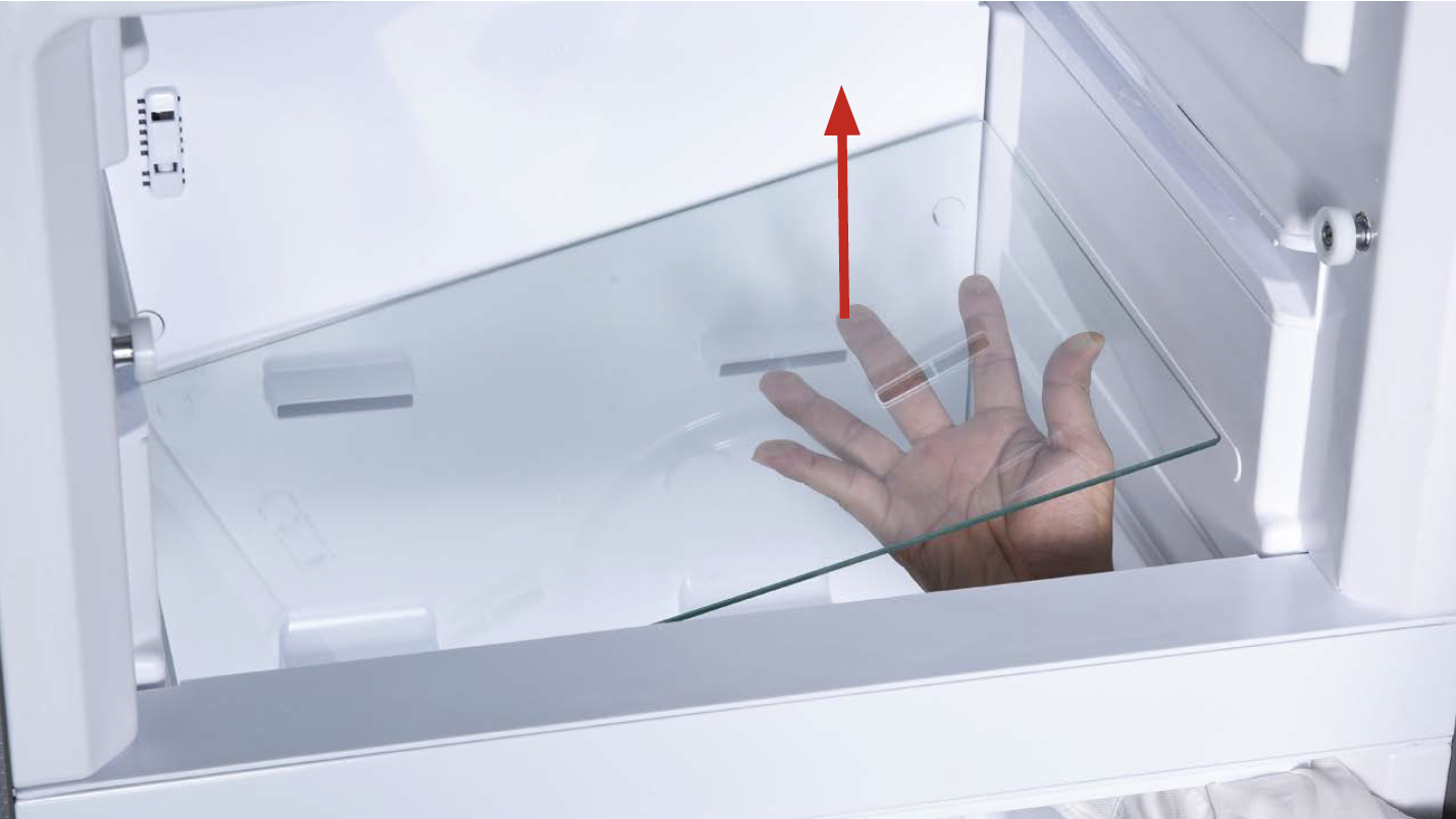
Remove the middle glass shelf located between upper and bottom freezer drawer compartments.
Step 4
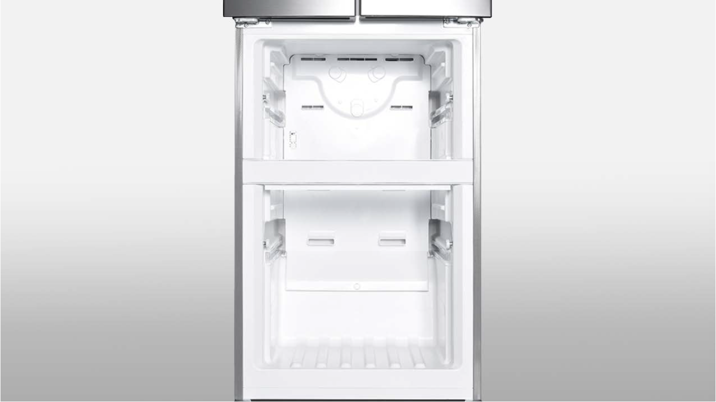
Unscrew air duct.
Check the freezer air
duct to find the three
screw covers.
Step 5
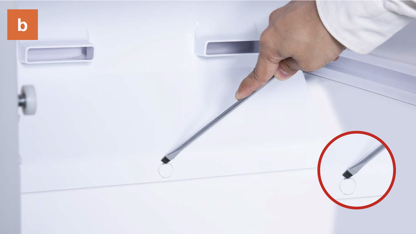
Remove the screw covers (total of three) on the air duct with slotted screw driver.
Step 6
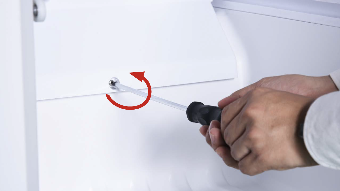
Unscrew all three screws with Cross-head screw driver.
Step 7
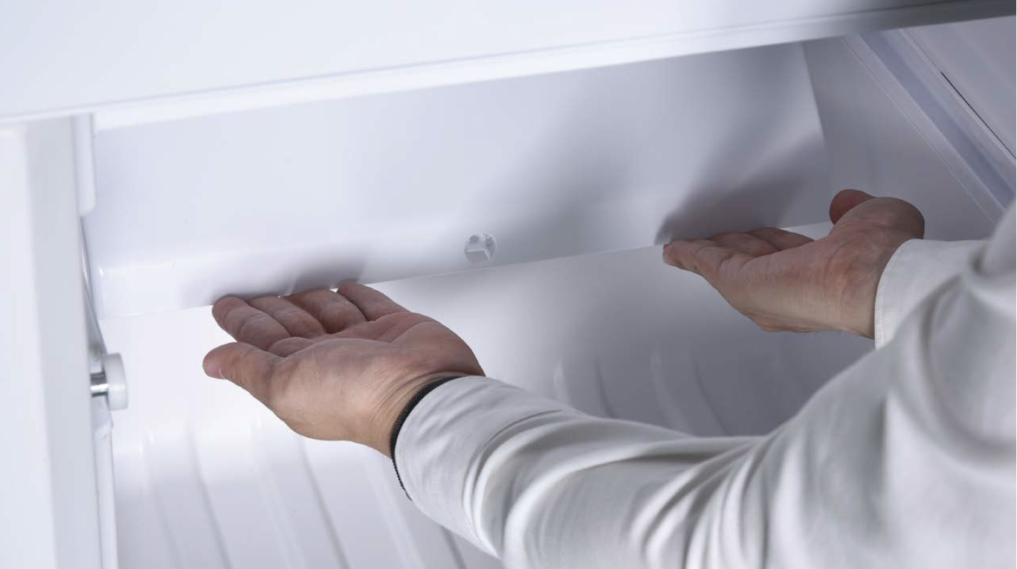
Dismantle the air duct.
Catch the bottom of air
duct.
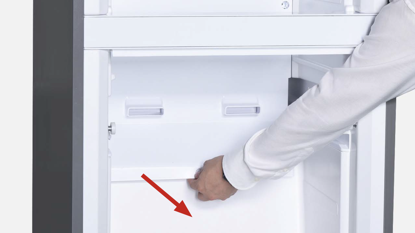
Step 8
Pull air duct out from the bottom of air duct.
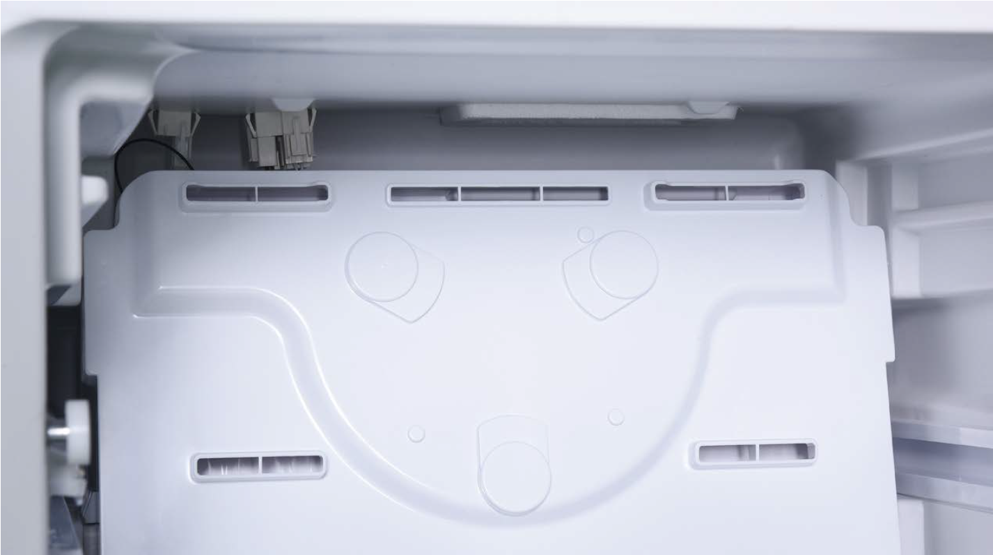
Step 9
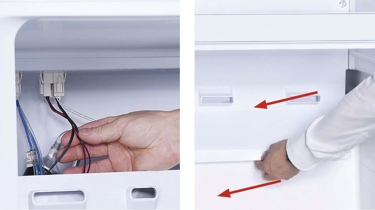
Pay attention to the connectors when pulling out the air duct.
Tip 1
When re-installing the air duct, move the wires out of the way so that they won’t be crushed by air duct.
Tip 2
After pushing air duct into position, it should make a click sound. If no click is heard, do it again.
CHECK AND TEST 2
Step 1
In duct area, check if terminal is pushed into final position.
Note
A & C are not OK; B is OK..

Step 2
Check if terminal is filled with foam or not.
IF YES, please use a needle to clean and remove the foam.
Later, reconnect the terminals
Power off the appliance and turn the power output of transformer to DC 12V.
Step 4
Supply power from terminal in PCB area.

DIAGNOSIS 2

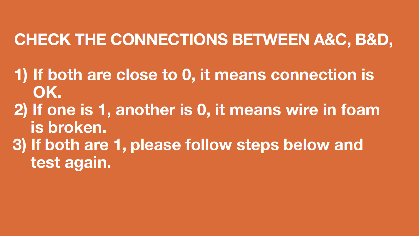
Step 2
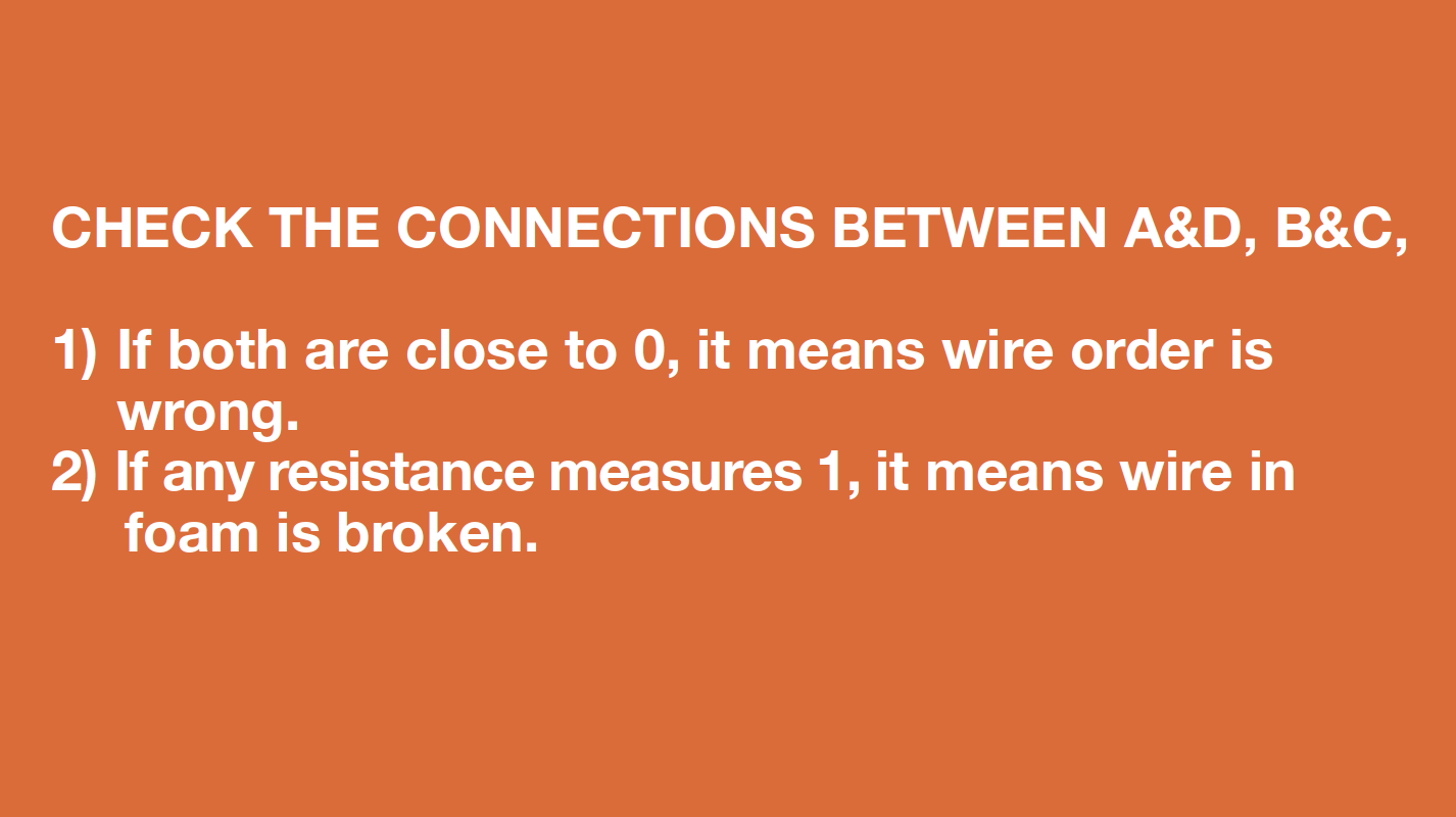
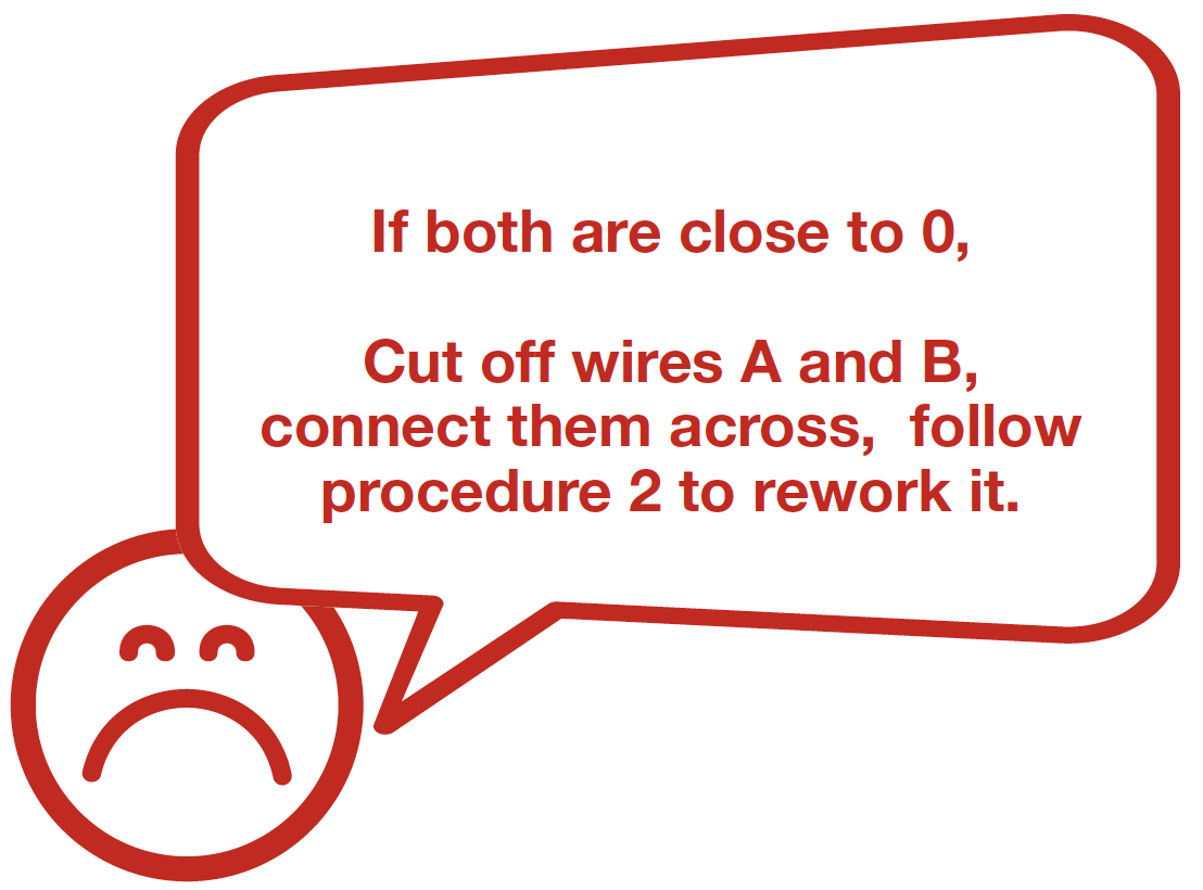
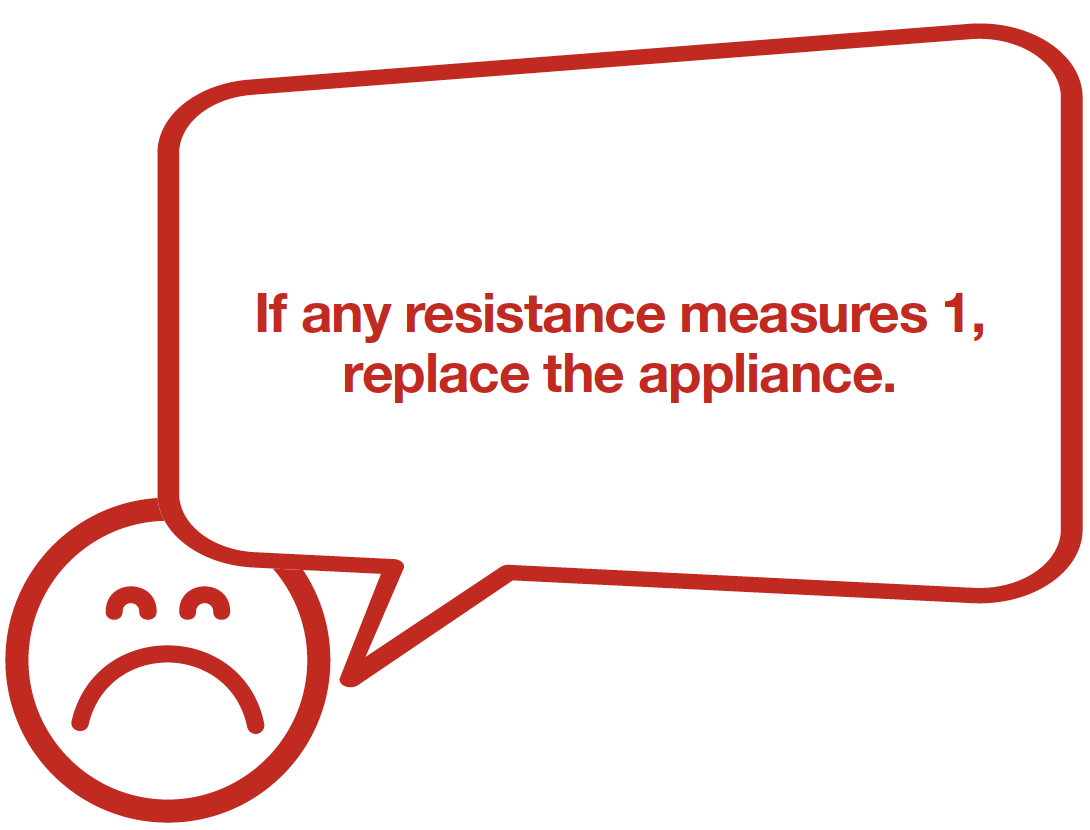
Check to see if the wires
are in the correct order
and their connections in
the foam are correct:
1. Set multimeter to
resistance gear;

2. Put detector into one end of wires in PCB area;
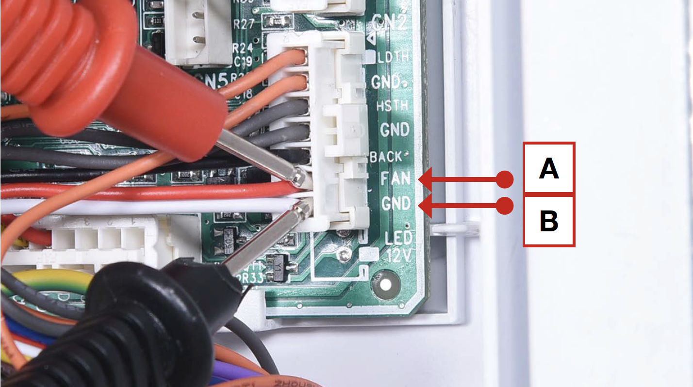
3. Put another detector into end of wires behind air duct.
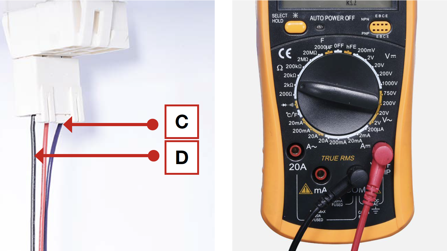

DIAGNOSIS 3

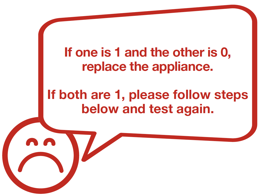

DIAGNOSIS 4
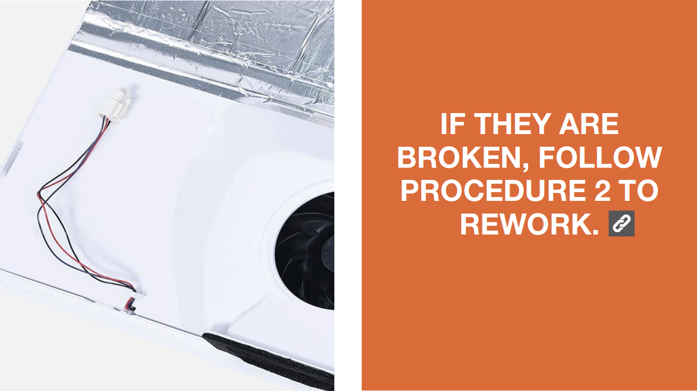
PROCEDURE 2

Step 1
Cut wire off.

Step 2
Peel off the sleeves.

Step 3
Check to ensure proper wire order and connect them.

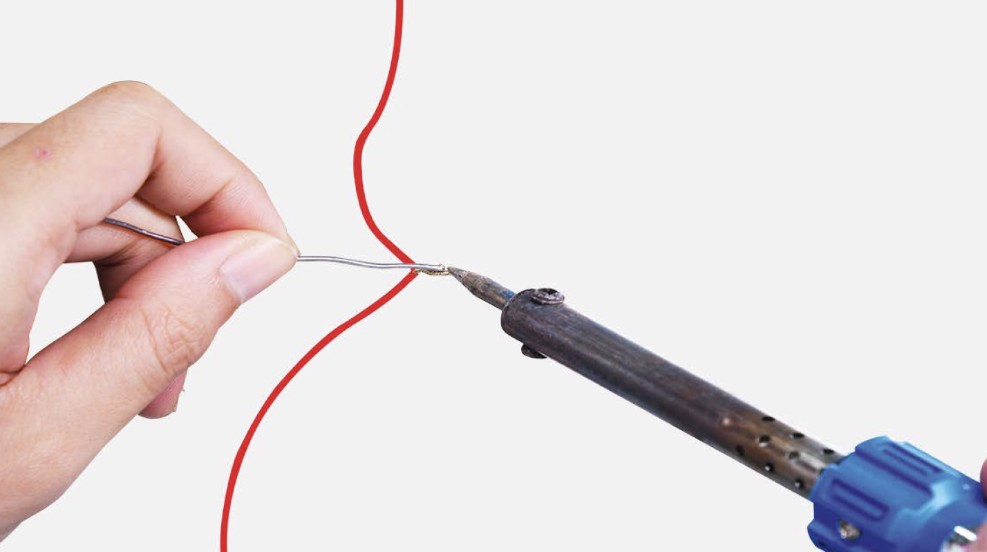
Step 4
Tin soldering.
Step 5
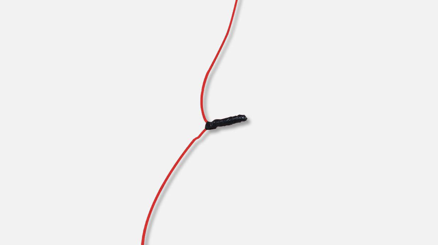
Cover connection with electrical tape.

CHECK AND TEST 4
Step 1
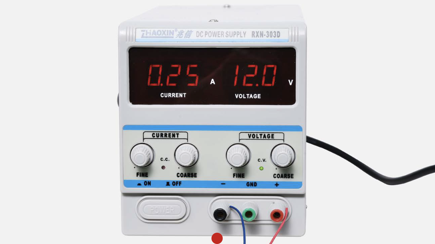
Set output of transformer to DC 12V to test fan from the terminal behind the air duct.
Step 2
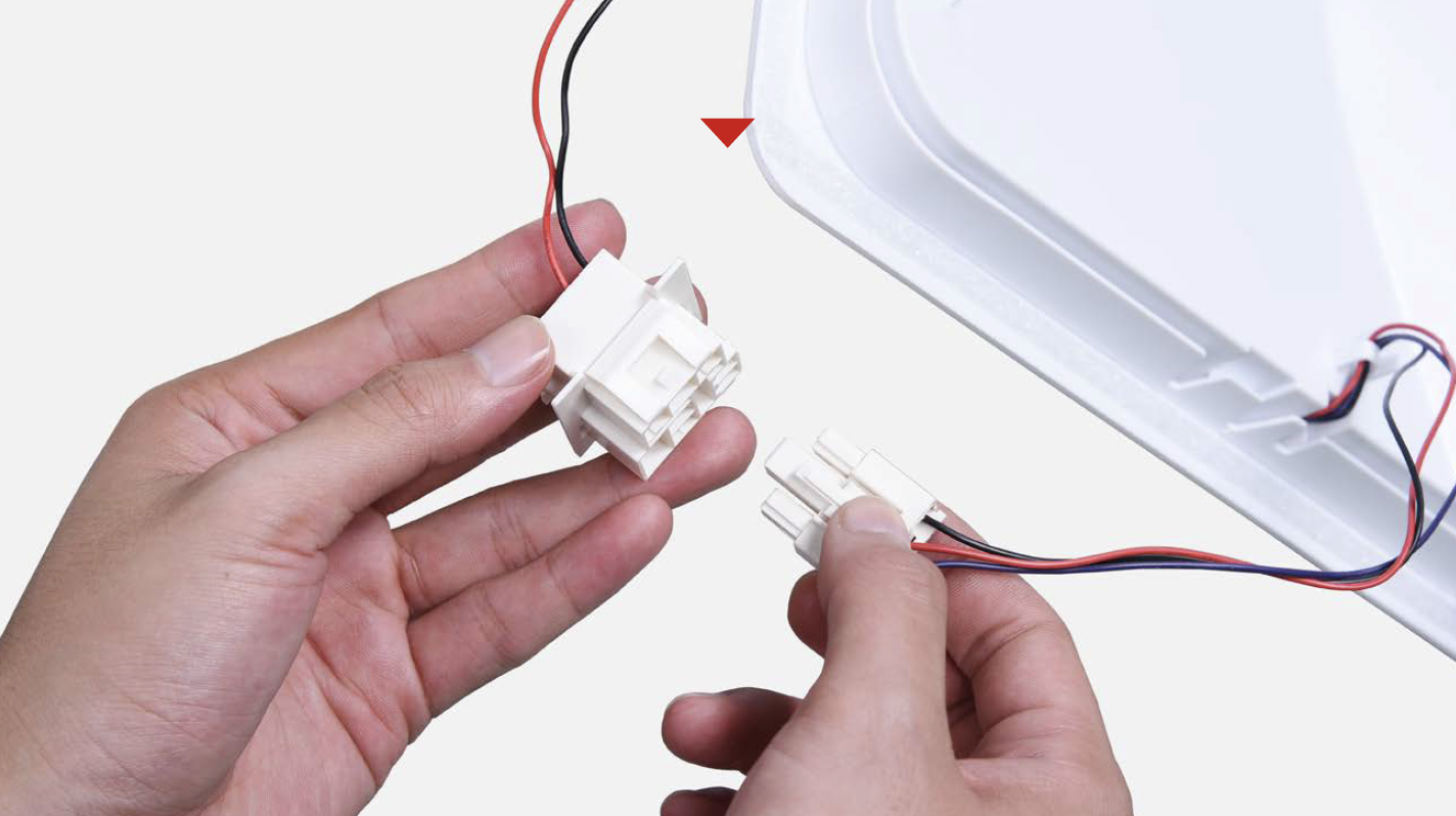
Use power source to test fan from terminal in the back of air duct.

DIAGNOSIS 5


Note
Tip 1
When re-installing the air duct, move the wires out of the way so that they won’t be crushed by air duct.
After pushing air duct into position, it should make a click sound. If no click is heard, do it again.

CHECK AND TEST 5
Step 1
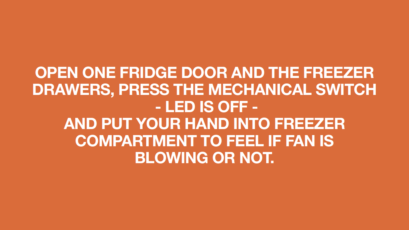
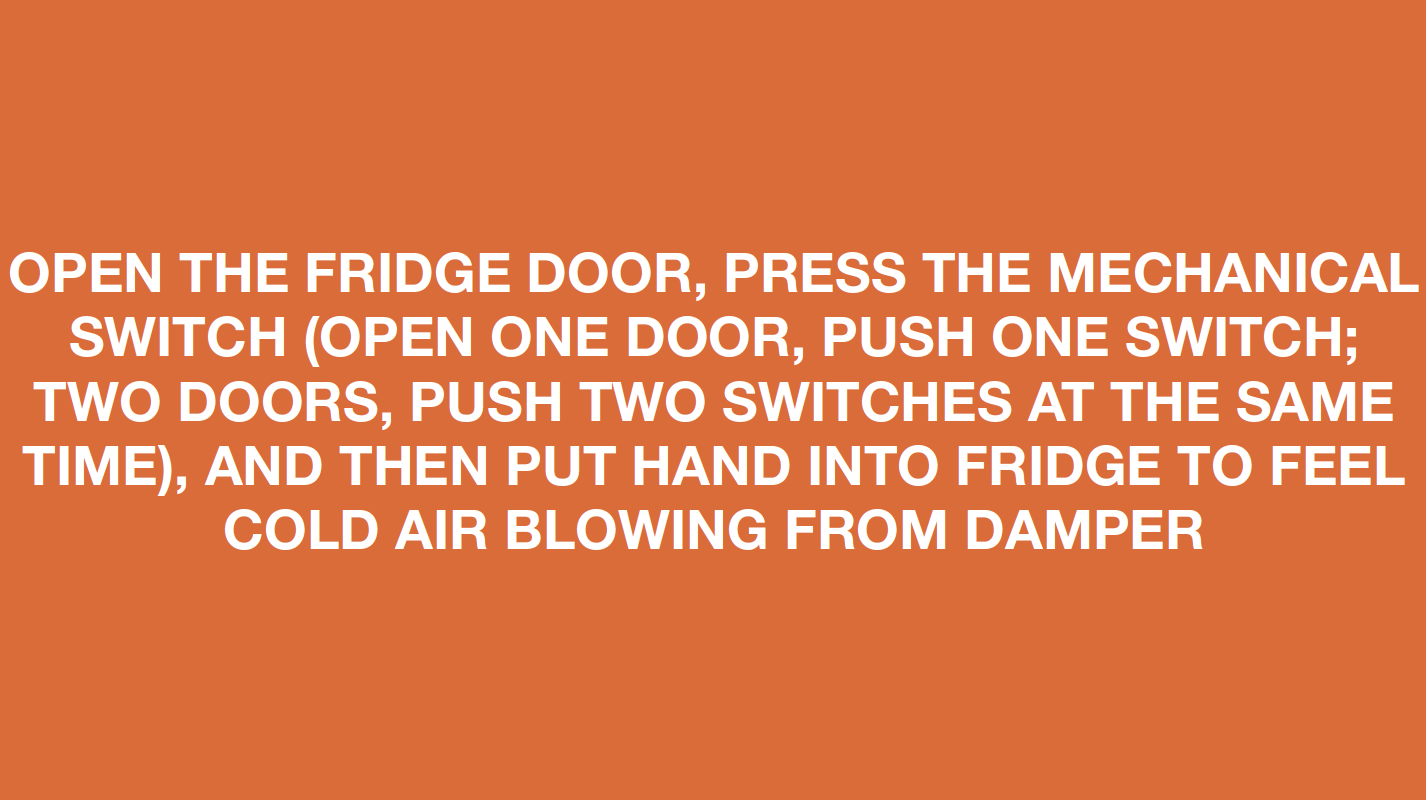
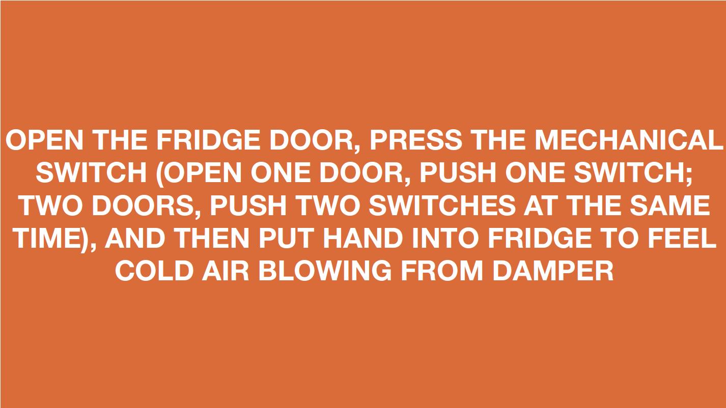
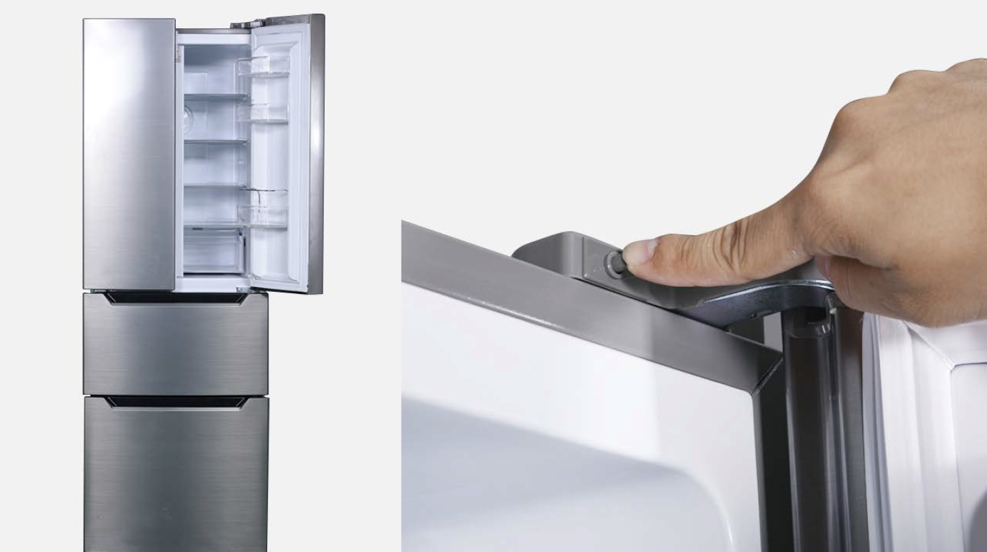
Open fridge door and freezer drawer, press the mechanical switch.

DIAGNOSIS 6
