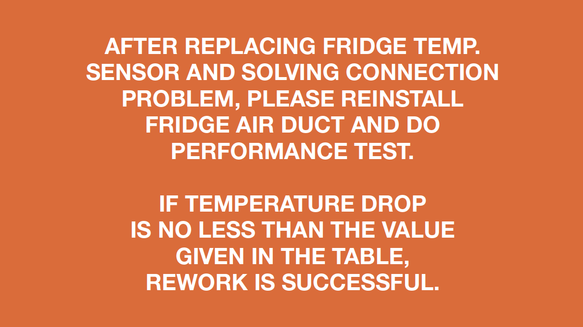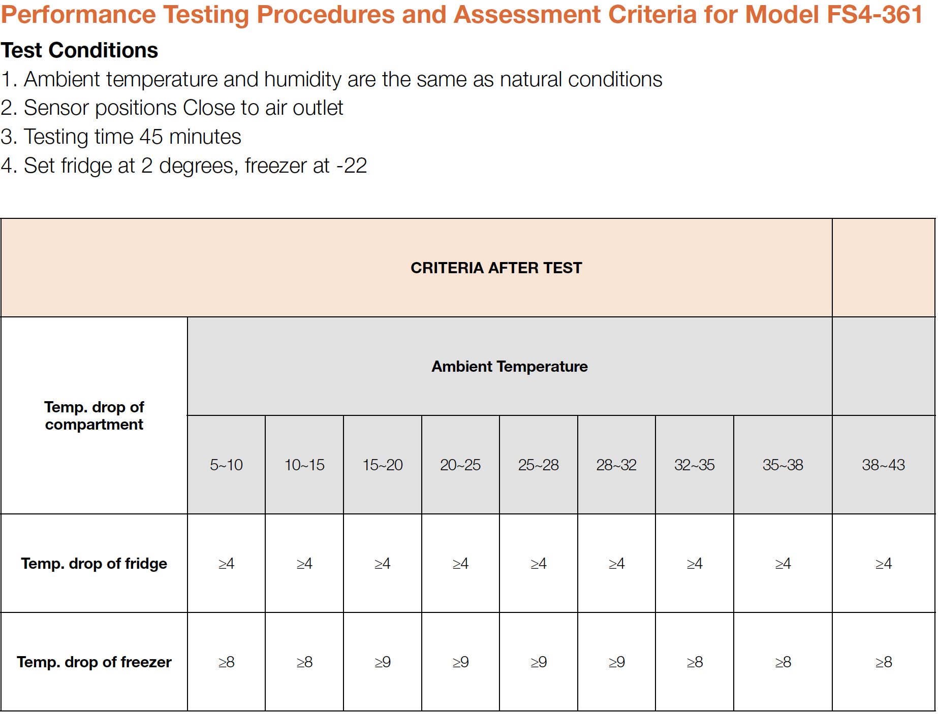


CHECK AND TEST 1
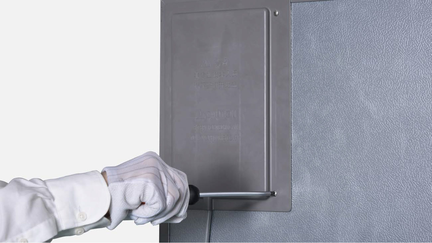
Step 1
Unscrew cover of mainboard with a cross-head screwdriver.
Step 2
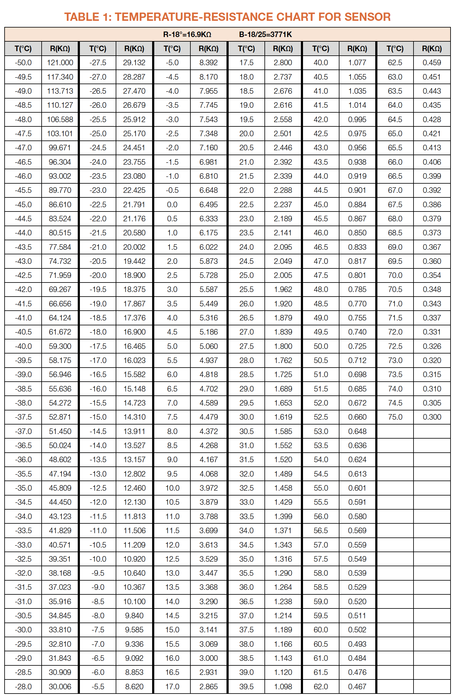
Test resistance of sensor from terminal in PC
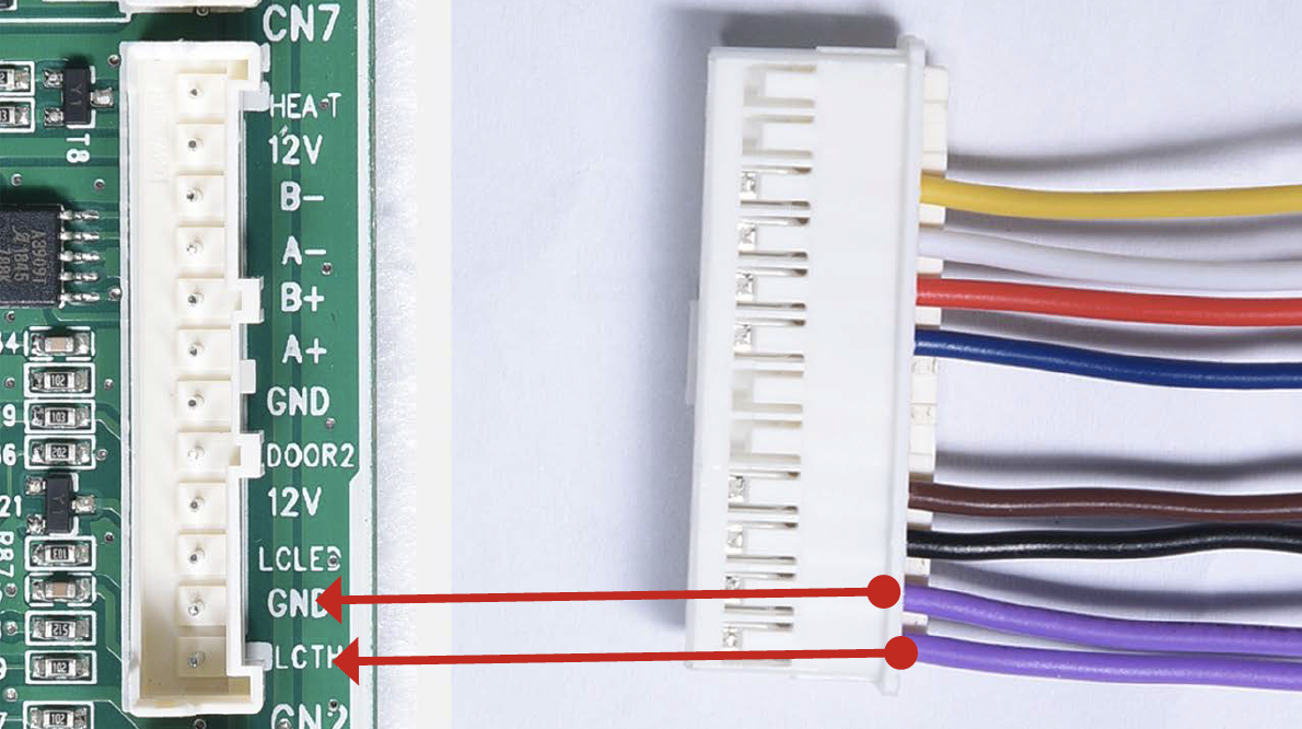
Step 3
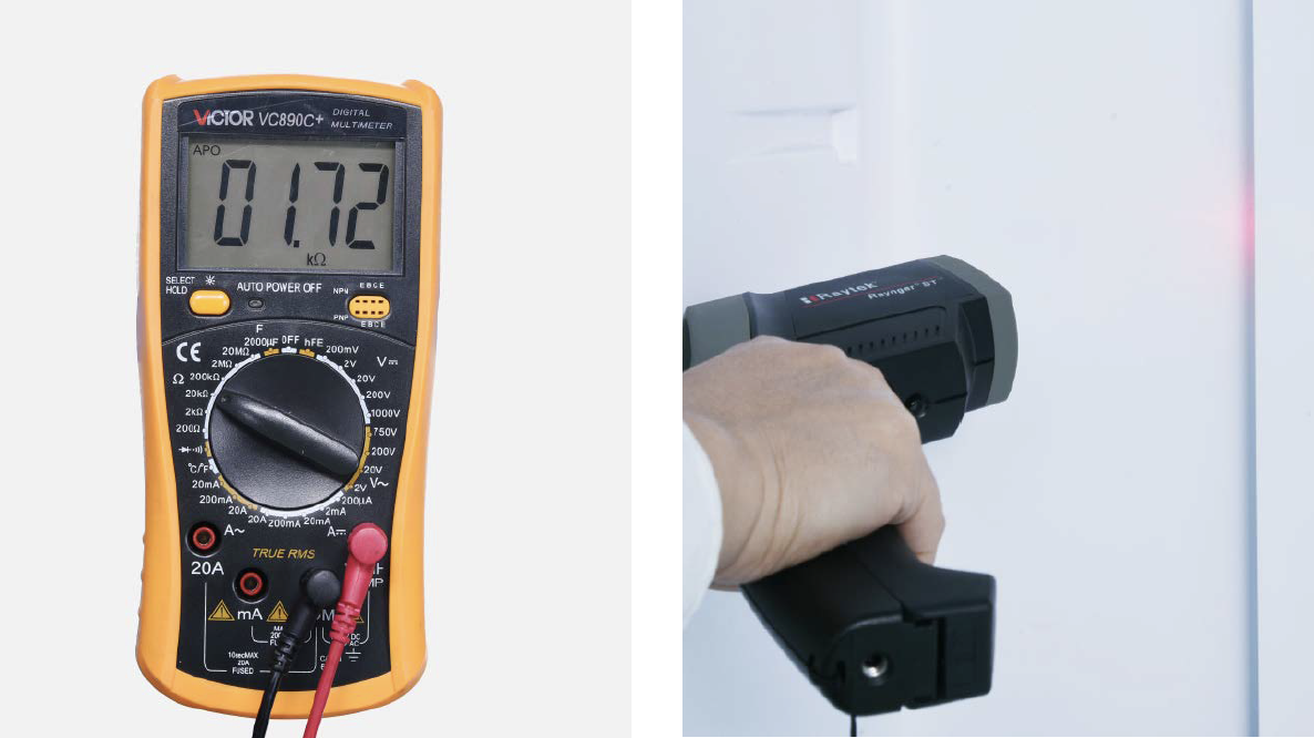
Take note of value.
Step 4
Measure the temperature of sensor.

DIAGNOSIS 1

PROCEDURE 1

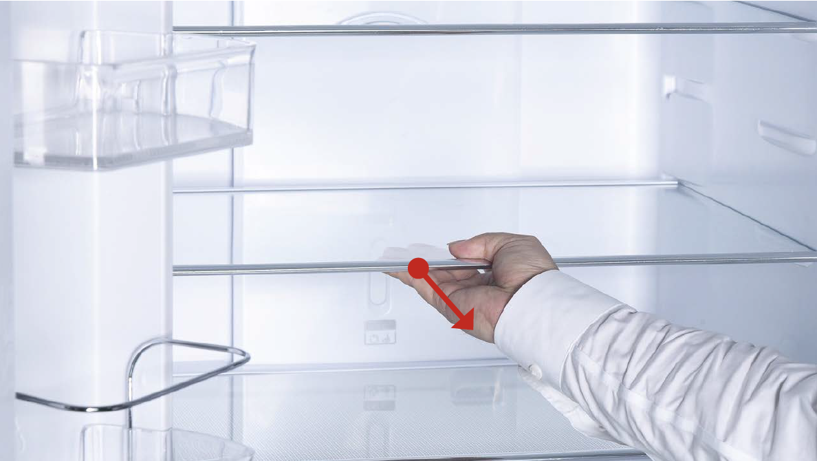
Step 1
Remove shelves.
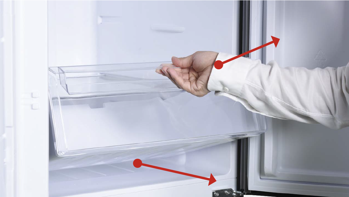
Step 2
Remove crispers.
Step 3
Remove shelf cover

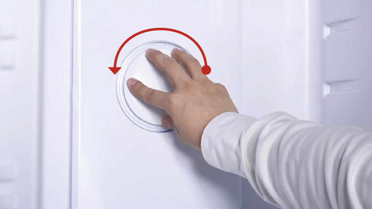
Step 4
Hold the cover and turn
in counter-clockwise
direction to loosen cover.
Then, remove cover.
Step 4
Hold the cover and turn in counter-clockwise direction to loosen cover. Then, remove cover.
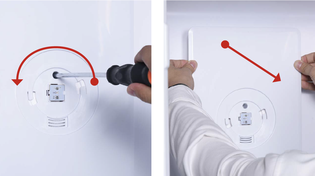
Step 5
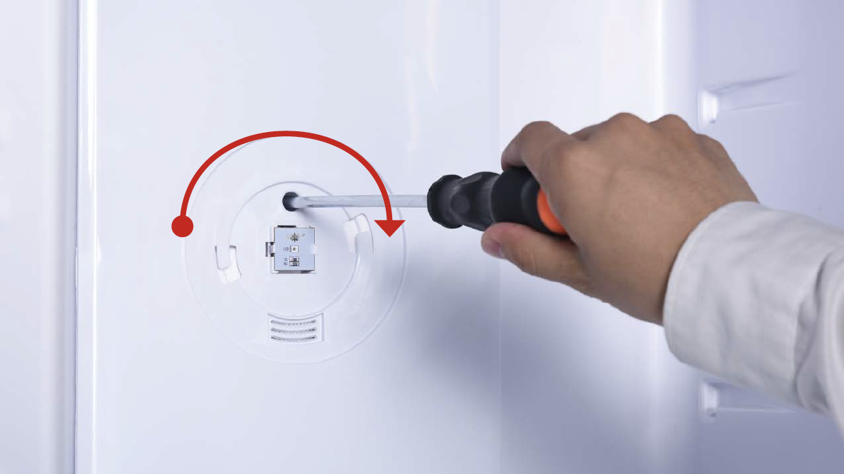
Use 6mm Cross-head
screwdriver to loosen the
screw.
Step 6
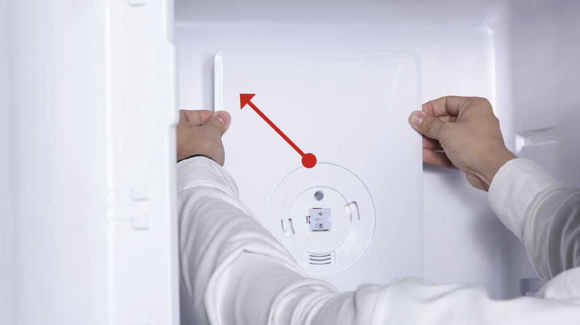
Hold the edge of air duct to remove.
Step 7
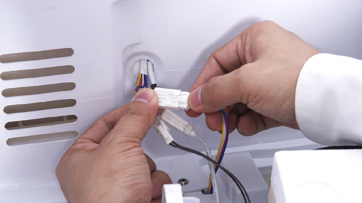
Disconnect the terminals.
CHECK AND TEST 2
Step 1
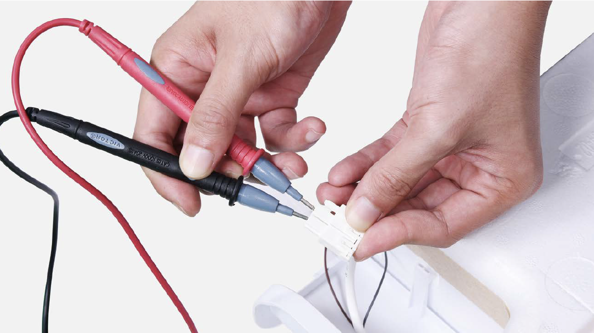
Test resistance of sensor from terminal in duct cover.
Step 2
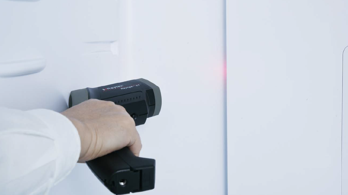
Measure temperature of fridge temp. sensor.

DIAGNOSIS 2
NOTE

PROCEDURE 2
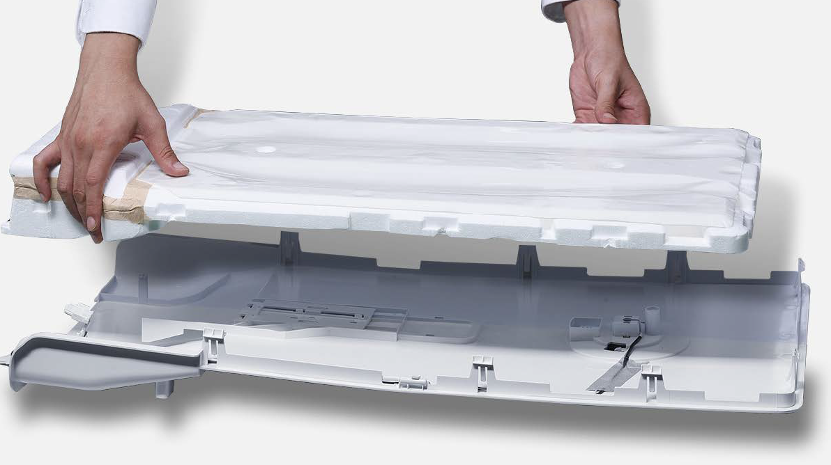
Step 1
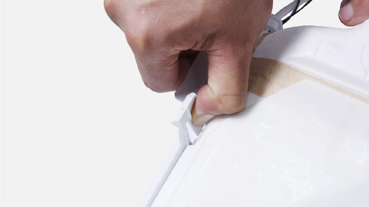
Release the clasp.
Step 2
Remove the foam air duct.
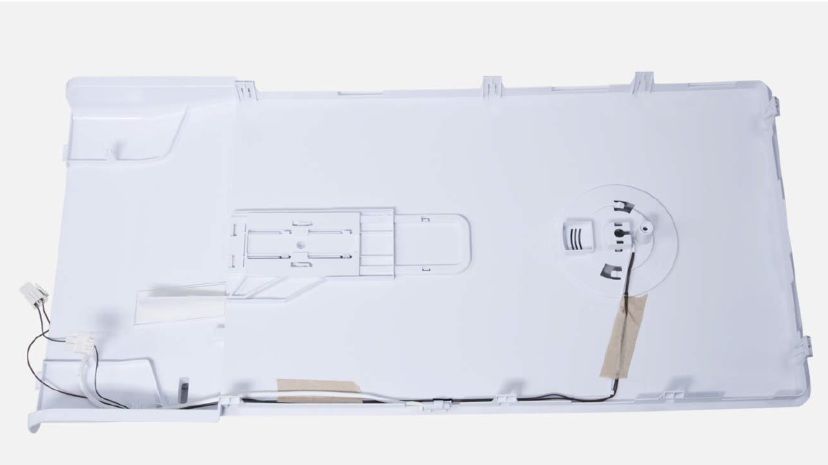
Step 3
Remove tape.
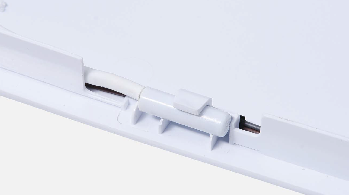
Step 4
Remove the broken
sensor.
NOTE
Reverse the
procedures to install
new sensor.
CHECK AND TEST 3
Step 1
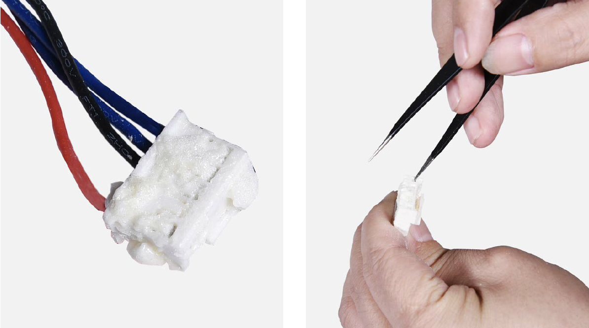
Check to see if terminal is full of foam.
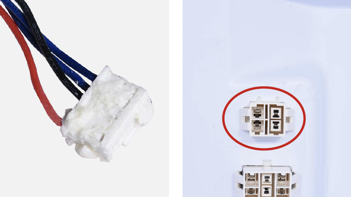
Step 2
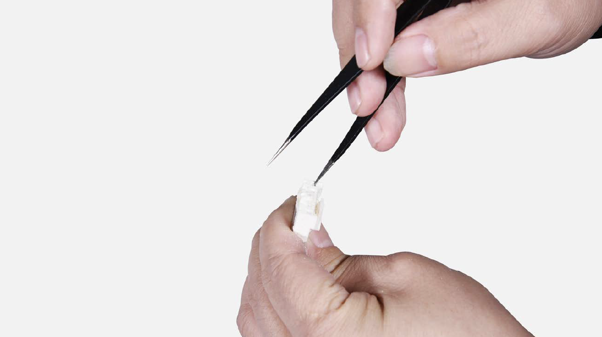
Use a needle or tools with sharp tip to remove foam in terminal.
Step 3
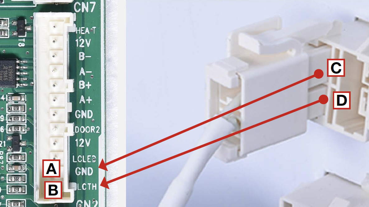
Check to ensure that wires are connected properly.
Step 4
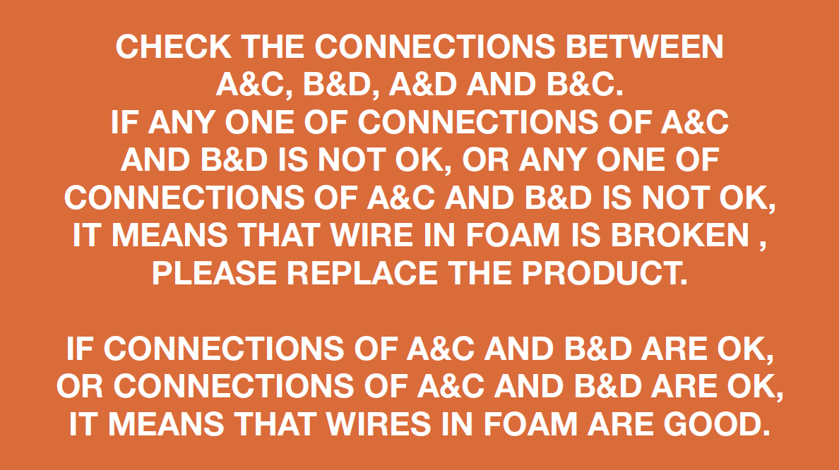
1. Put detector into one
end of wires in PCB
area;
2. Put another detector into end of wires behind air duct.


DIAGNOSIS


PROCEDURE 3
Step 1
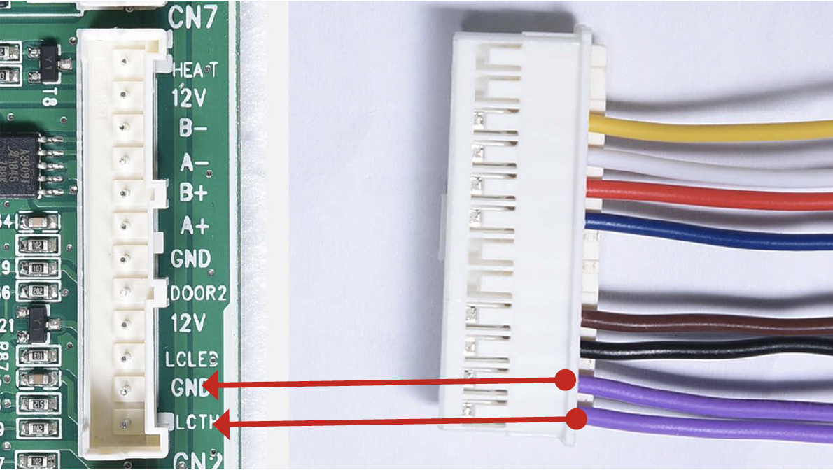
Reinsert the terminals for sensor.
Make sure that the terminal is pushed into final position
Step 2
Screw on the cover of mainboard with a cross-head screwdriver.

Step 3
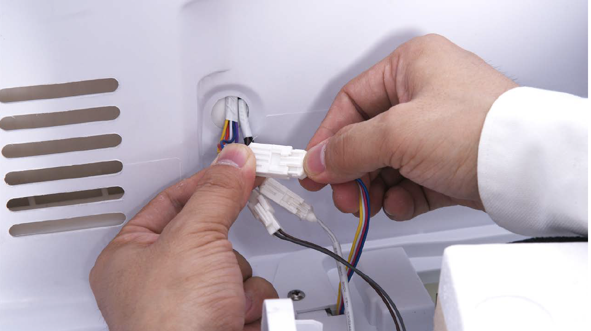
Re-connect the terminals.
Step 4
Hold air duct by edges to put it back in place.
Step 5
Use a 6 mm cross-head screwdriver to tighten the screw clockwise.
Step 6
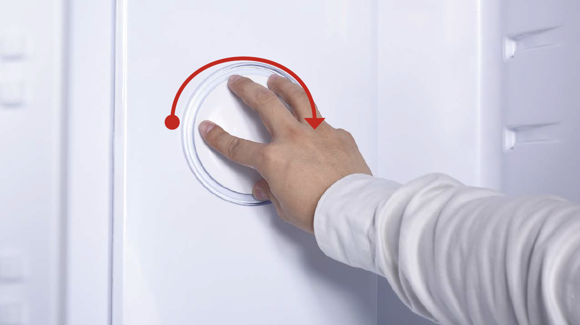
Hold the cover and turnit clockwise to tighten
the lid, then pull outwards.
Step 7
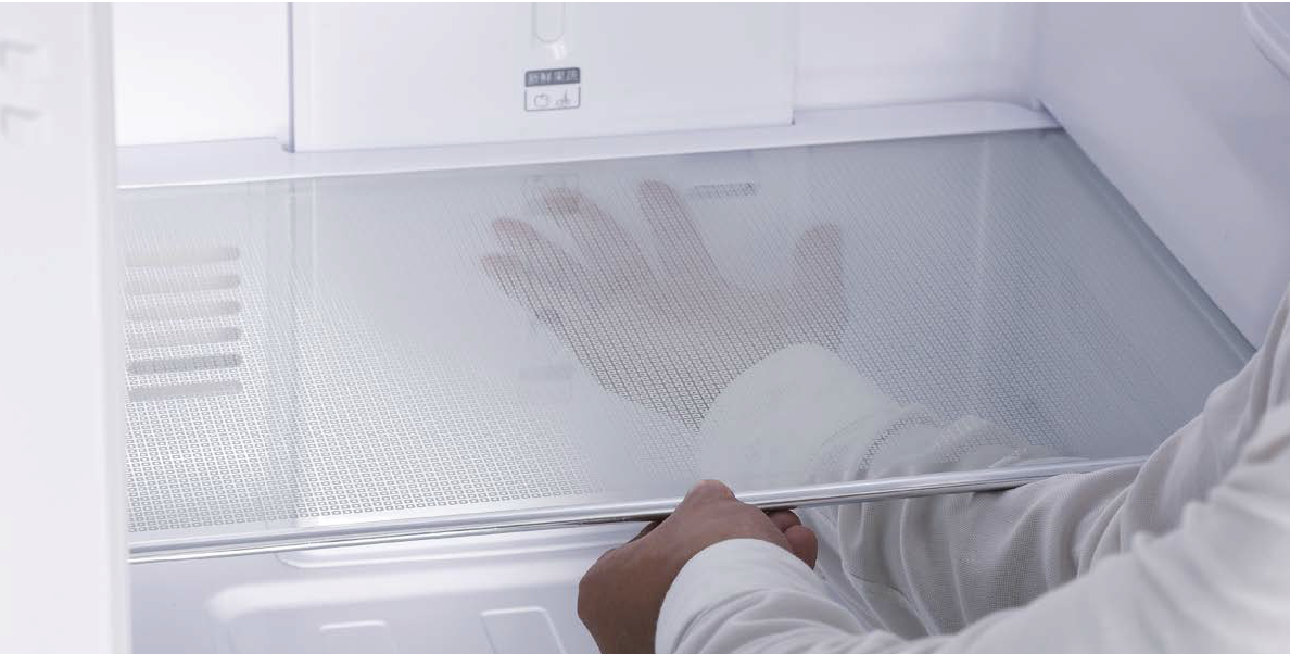
Insert shelves.
TIPS DURING INSTALLATION PROCEDURES FOR FRIDGE AIR DUCT.
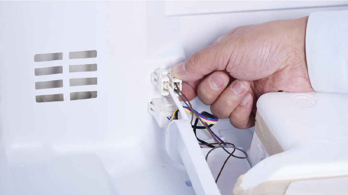
Tip 1
Connect the terminals.
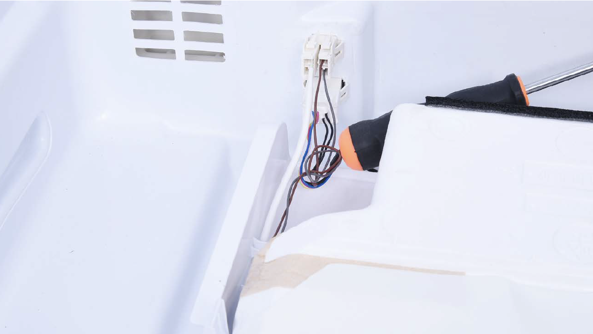
Tip 2
Push terminals into place, then move wires to prevent crushing of wires with edge of air duct.
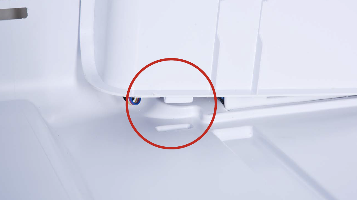
Tip 3
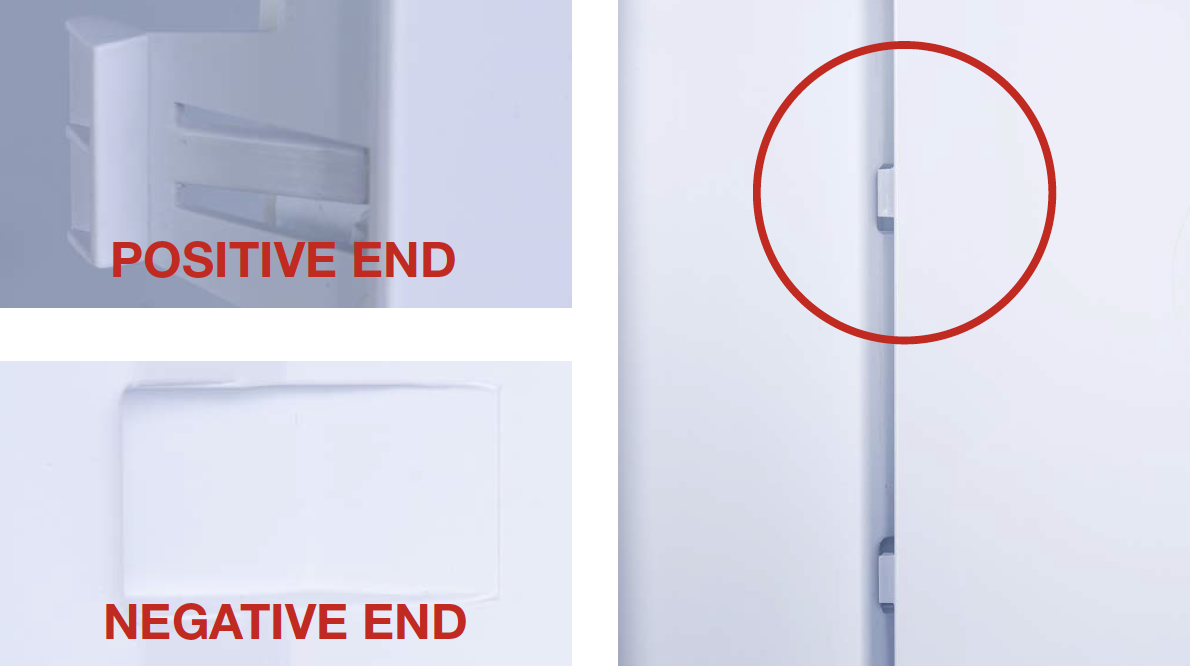
When reinstalling the air duct, first insert positive shaft into the negative hole.
Tip 4
Then, fasten the clasp on top using the same method.

DIAGNOSIS 4
