

CHECK AND TEST 1
Step 1
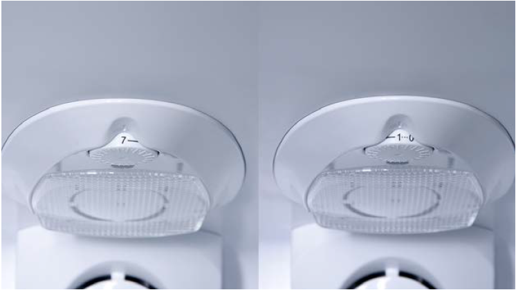
Check if Gear is set to max (such as 6 or 7).
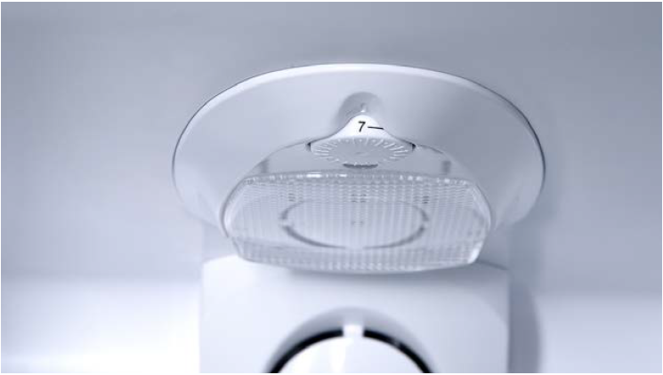
Step 2
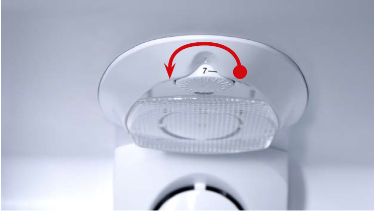
If gear is set close to Max (such as 6 or 7) and
compressor is always running, turn knob slowly to warmer gear until the compressor stops.

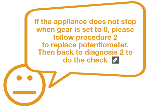
DIAGNOSIS 1
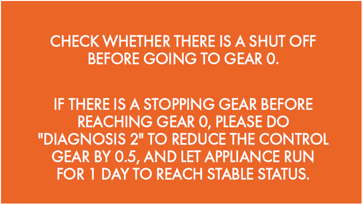
Note
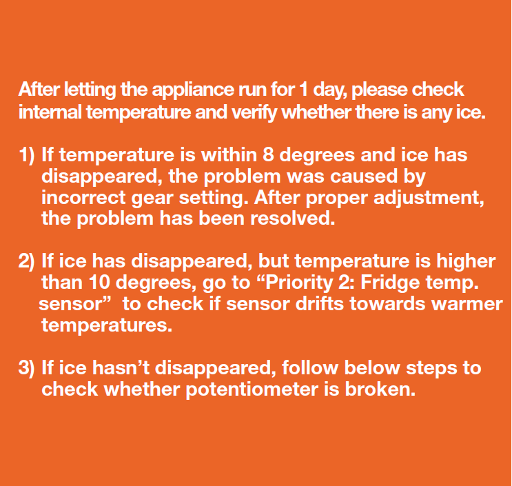
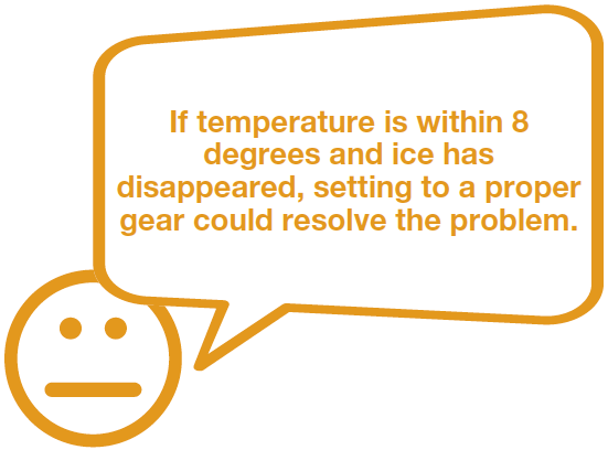
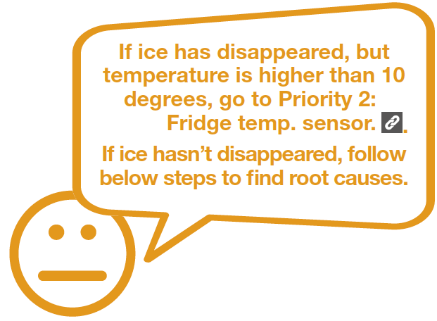
Check for stable status after gear adjustment.

CHECK AND TEST 2
Step 1
Unscrew.
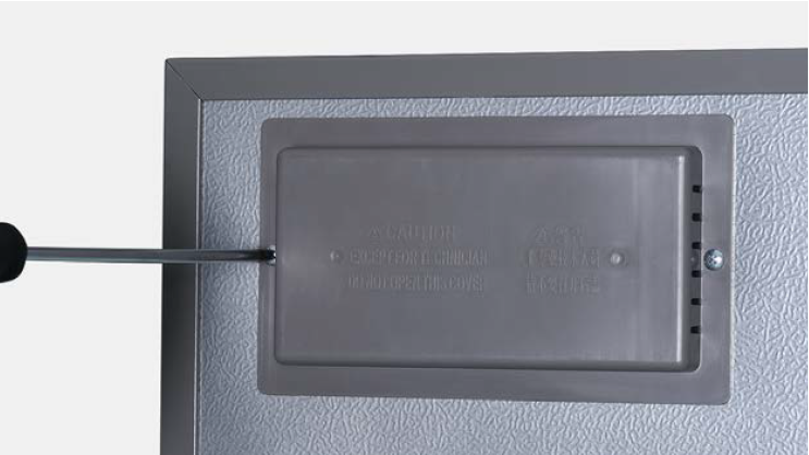
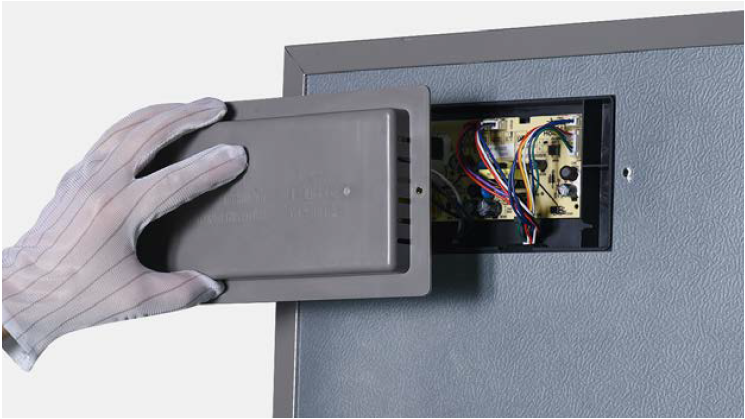
Step 2
Remove the mainboard cover.
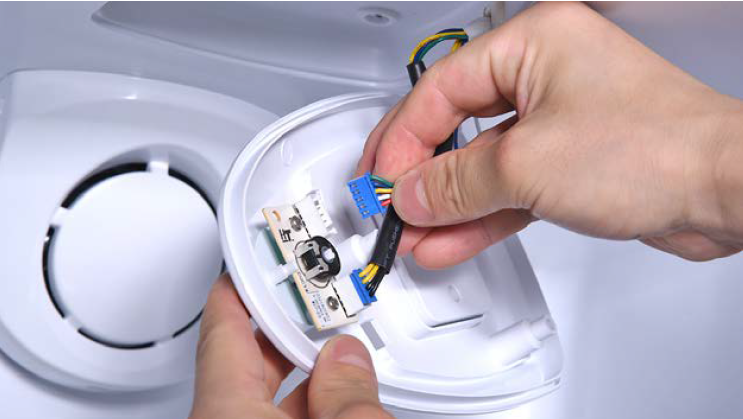
Step 3
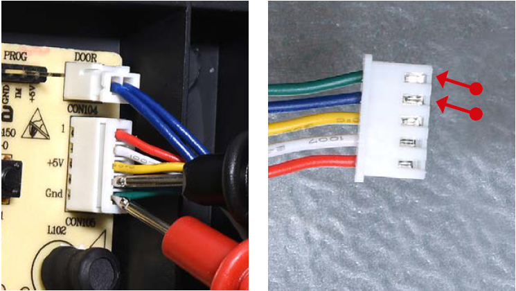
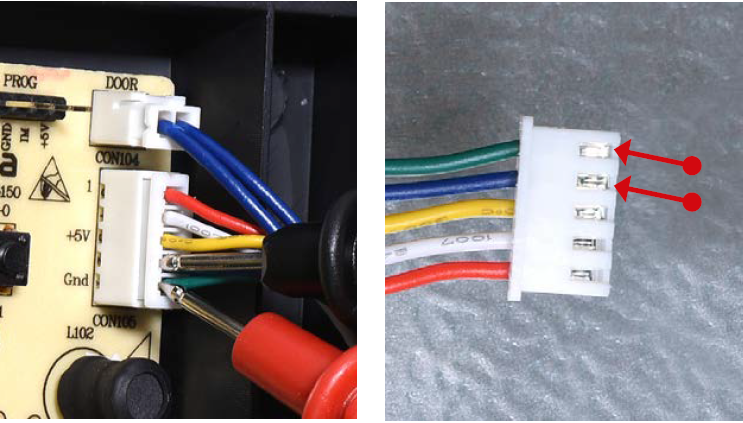
Check if terminal is loose, full of foam.
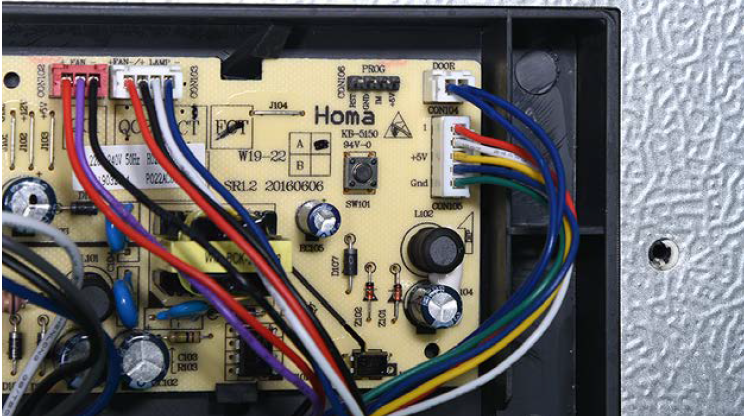
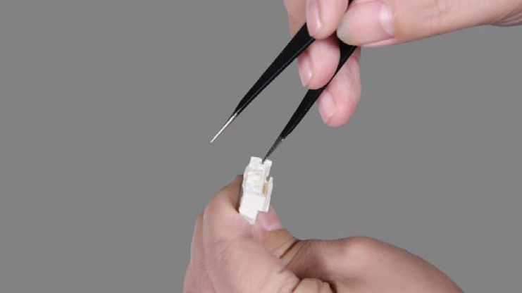
Step 4
If loose, reinsert the terminal. If terminal is full of foam, use tweezers to remove foam.
Step 5
Set potentiometer from max to min.
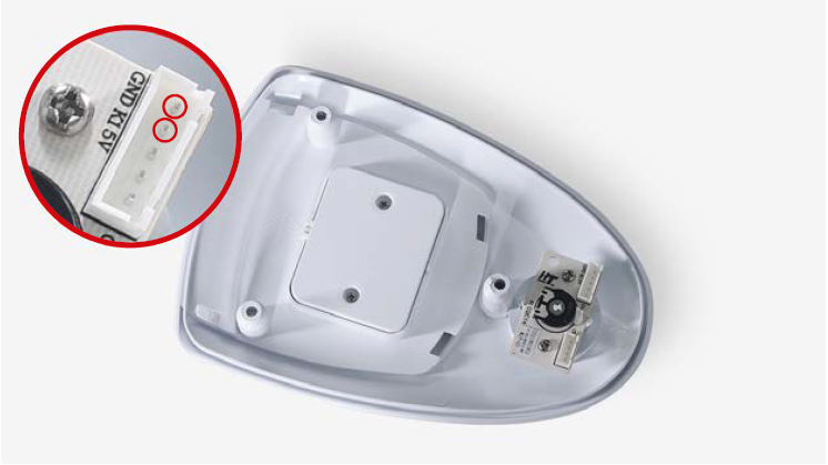
Step 6
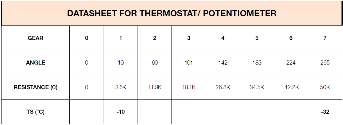
Test resistance of potentiometer at each
gear from terminal in PCB area.


CHECK AND TEST 3
Step 1
After removing foam from terminal and reinserting the terminal, please re-test resistance of potentiometer from terminal in PCB area.


Step 1
Lever LED cover off.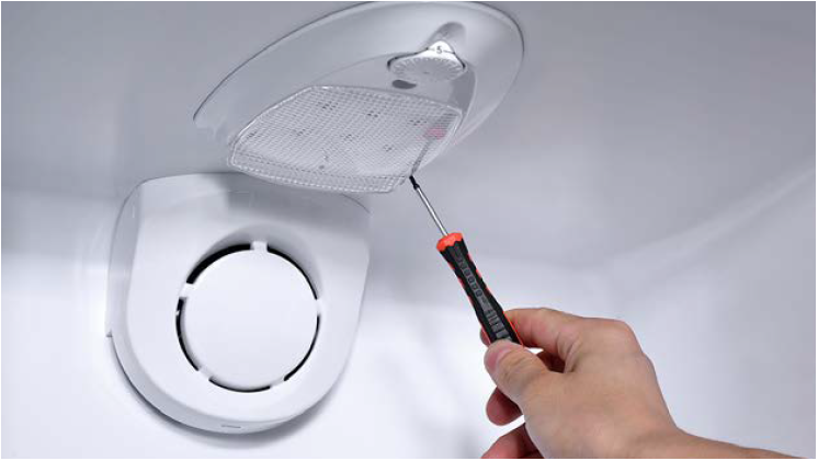
Step 2
Remove LED cover.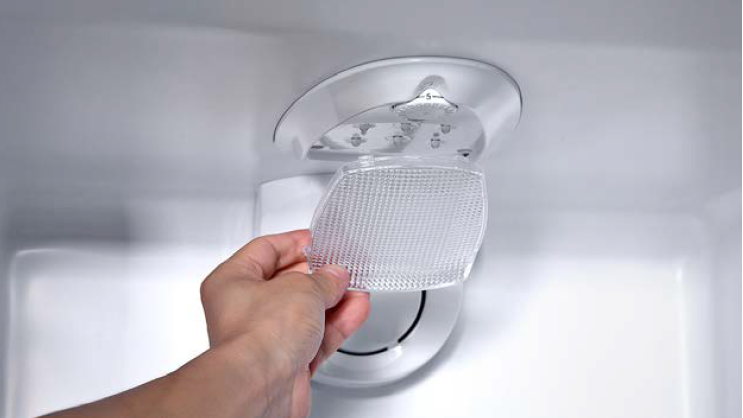
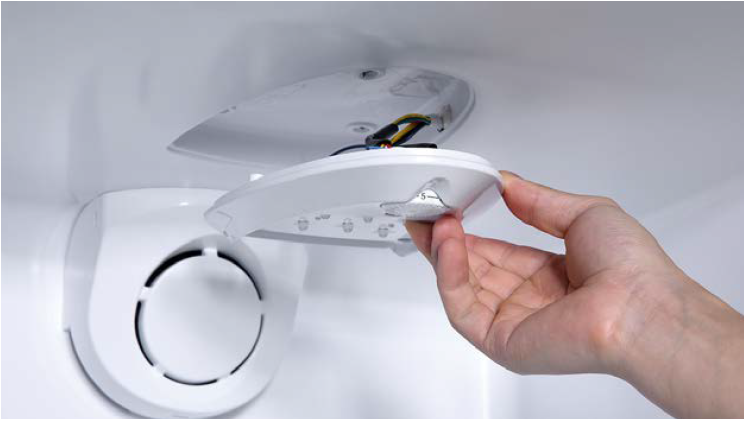
Step 3
Unscrew potentiometer
cover.
Step 4
Remove cover from cavity.

Step 5
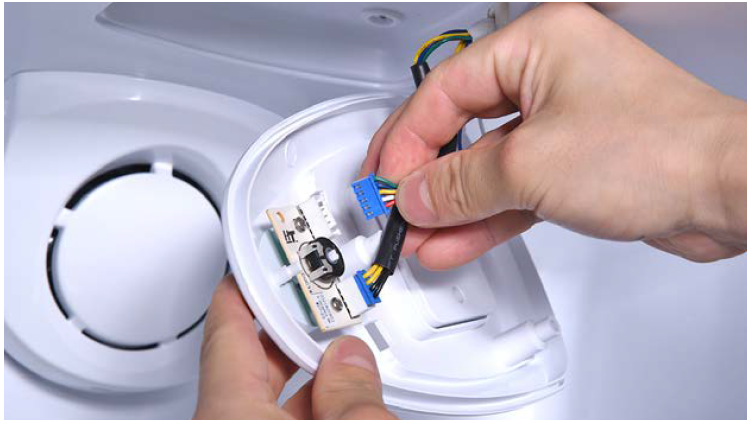
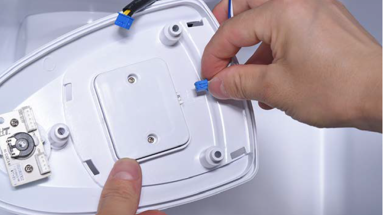
Disconnect terminal for potentiometer.
Step 6
Disconnect terminal of LED.

Step 7
Unscrew.
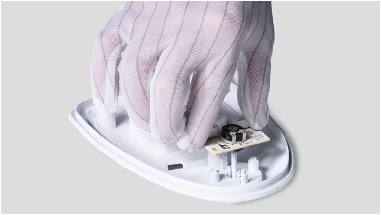
Step 8
Take the potentiometer away.

CHECK AND TEST 4
Step 1
Test resistance of potentiometer from terminal in PCB area
.
CHECK AND TEST 5
Step 1
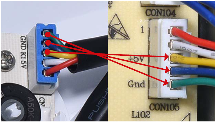
Check the connection of wires in foam.

Step 1
Lever LED cover off.
Step 2
Remove LED cover.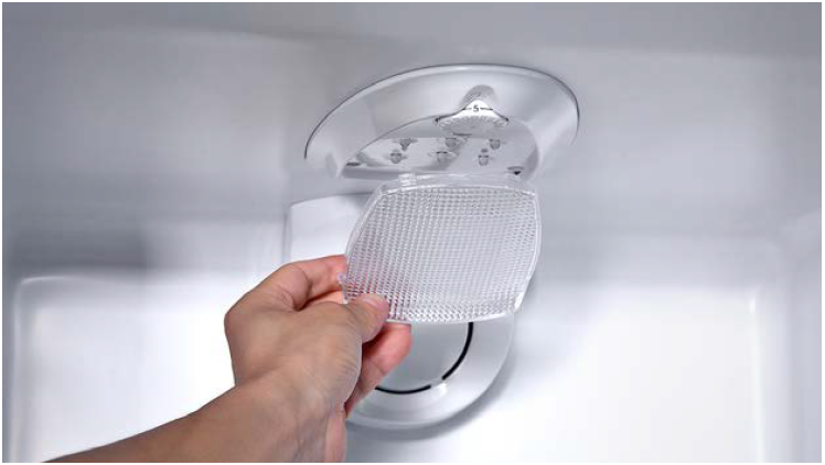
Step 3
Unscrew potentiometer
cover.

Step 4
Remove cover from cavity.
Step 5
Disconnect terminal for potentiometer.
Step 6
Disconnect terminal of LED.
Step 7
Unscrew.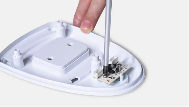
Step 8
Take the potentiometer away.
Reverse above procedures to install
potentiometer PCB, LED PCB, and cover
back onto cabinet.

GO BACK TO COMPONENT LIST