
CHECK AND TEST 1
Step 1
Unscrew.
Step 2
Remove the mainboard cover.

Step 3
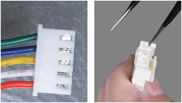
Check if terminal is pushed into final position.

Step 4
Check to see if terminal is full of foam. If so, use tweezers to remove foam.
Step 5
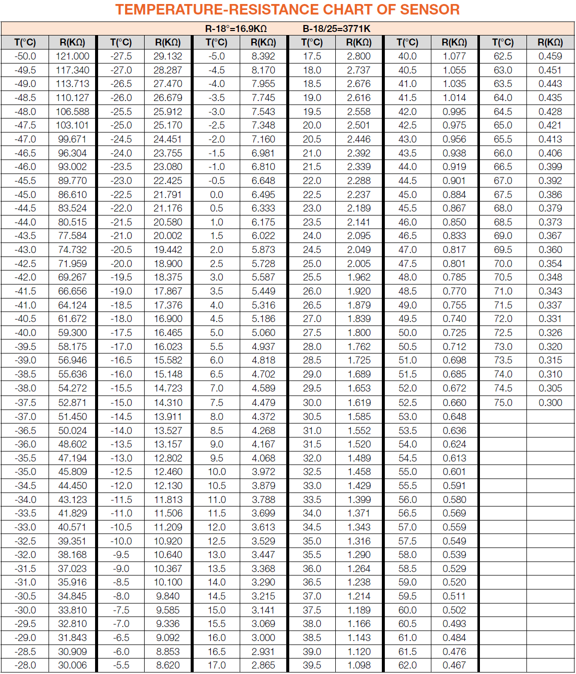
Use multimeter to measure resistance value.

Step 6
Record the value.

Step 7
Test temperature on air duct close to sensor.
Use tested temperature to find out the reference resistance in following chart.


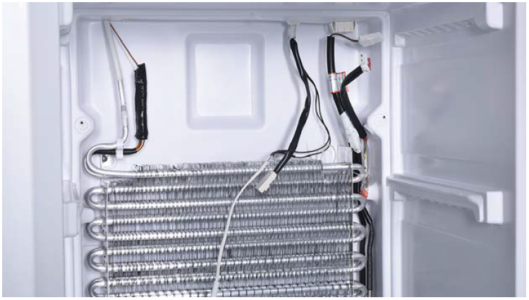
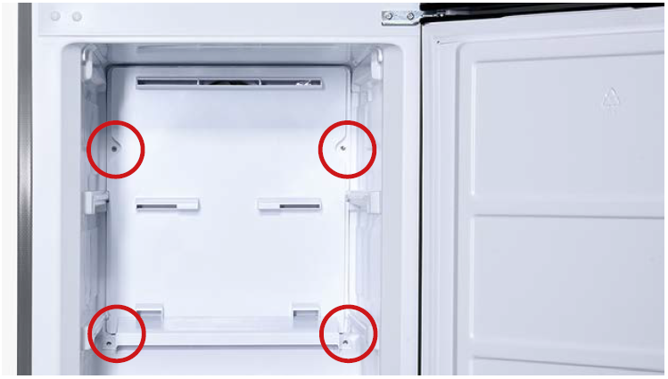
DIAGNOSIS 1


PROCEDURE 1

Step 1
Pull out the drawers.
Step 2
Take out the shelves.

Step 3
Unscrew the 4 screws.
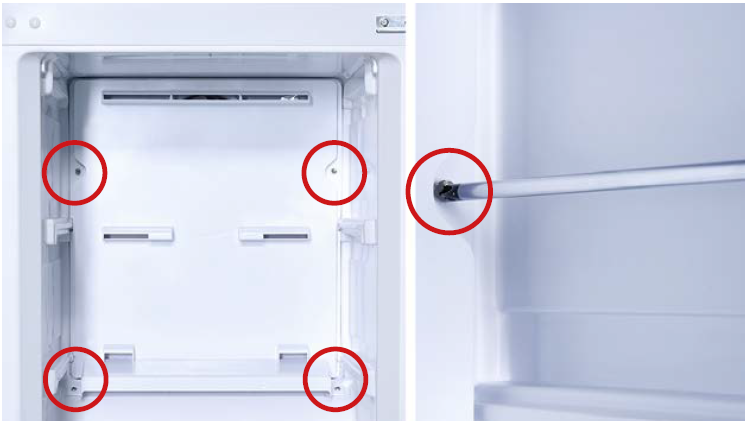
Step 4
Hold the bottom of air duct and pull it out.

Step 5
Disconnect the terminal of fan motor.

Step 6
Remove air duct.

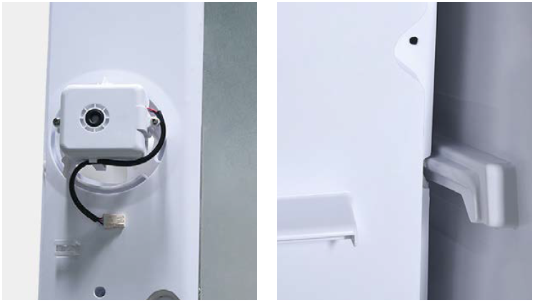
CHECK AND TEST 2
Step 1
Check to see if sensor is in right position.
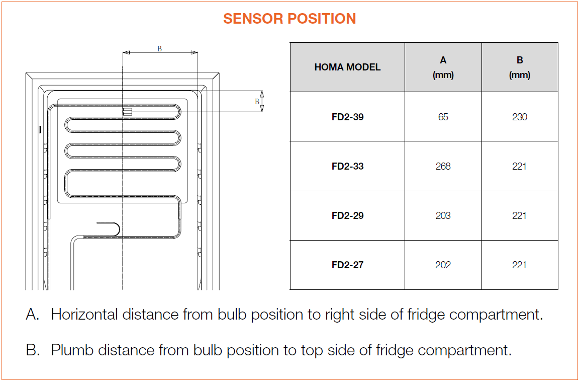


DIAGNOSIS 2


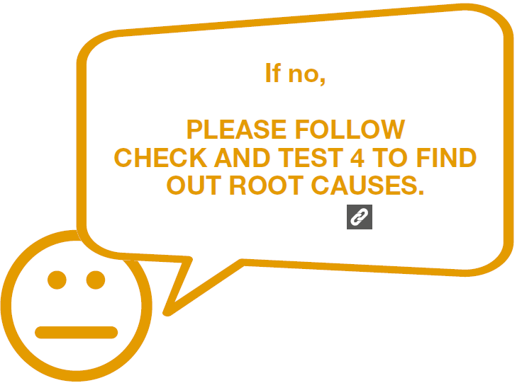
CHECK AND TEST 3
Step 1
Check to see whether sensor wires are cut off.
DIAGNOSIS 3
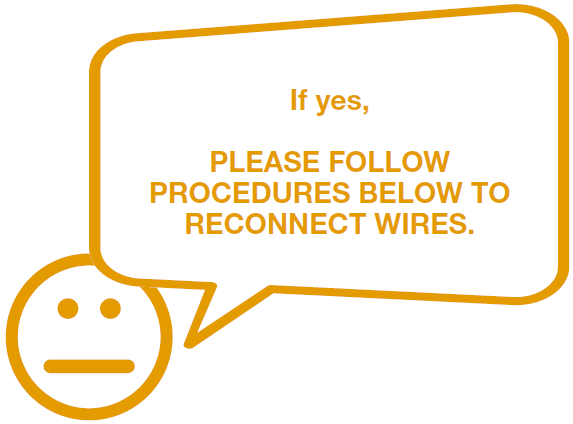


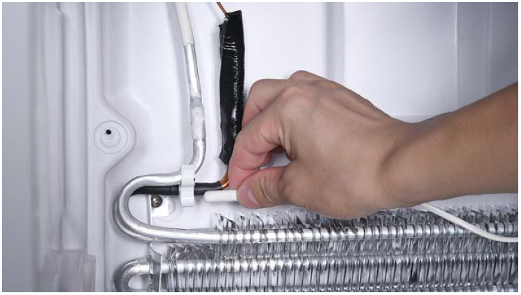
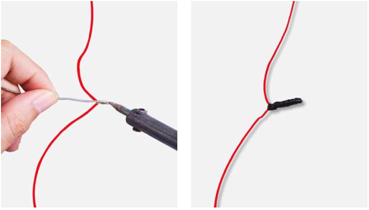
Step 1
Cut wire off from broken area.

Step 2
Peel off the sleeves.
Step 3
Check to ensure proper wire order and connect
them.

Step 4
Tin soldering.
Step 5
Cover connection with electrical tape.
CHECK AND TEST 4
Step 1
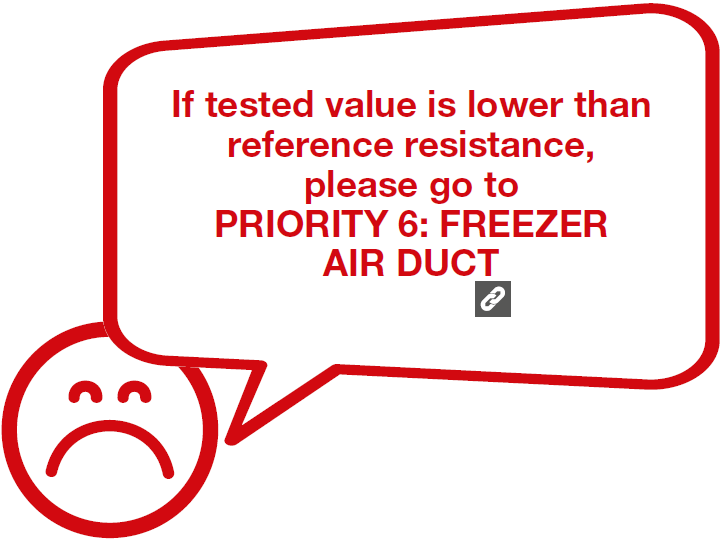
Test resistance of sensor.
Step 2
Read the value.
Step 3
Measure the temperature of sensor.


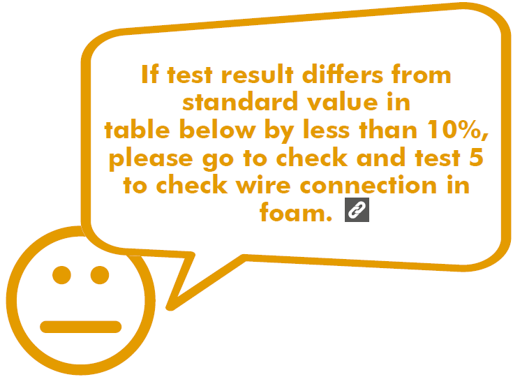

CHECK AND TEST 5
Step 1
Connect the 2 ends in
PCB ends.

Step 2
Test connection.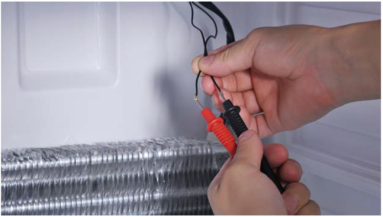


Tip 1
Before installing the airduct, please tie all wires
together.

Tip 2
fan well.
Tip 3
Insert left side first, then other side. Make sure
the cavity on the side is aligned with the ribs on
inner liner.
Tip 4
Check to see if there is a wide gap between air
duct and cabinet. If so, install air duct again.

GO BACK TO COMPONENT LIST