
CHECK AND TEST 1
Step 1
Unscrew.
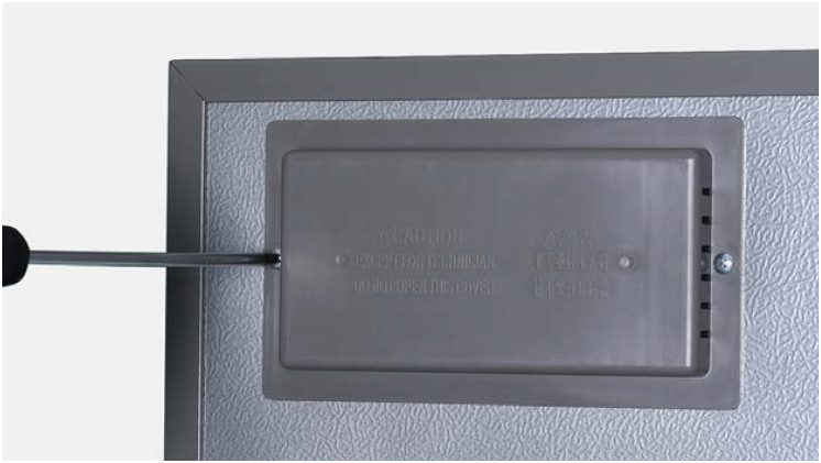
Step 2
Remove the mainboard cover.

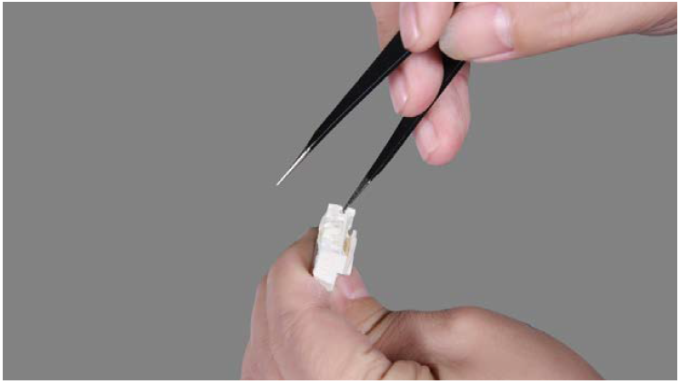
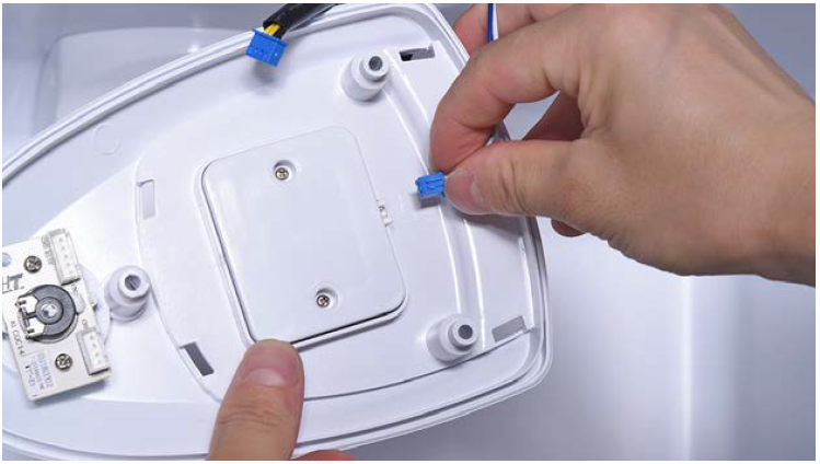
Step 3
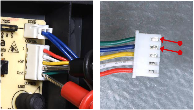
Check if terminal is loose, full of foam.

Step 4
If loose, reinsert the terminal.
If terminal is full of foam, use tweezers to remove foam.
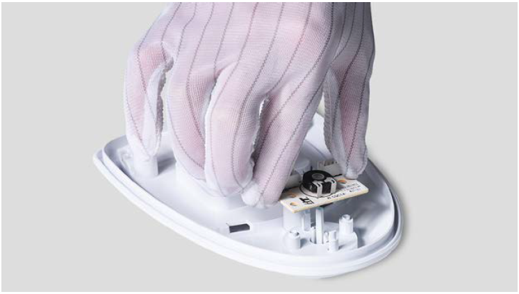
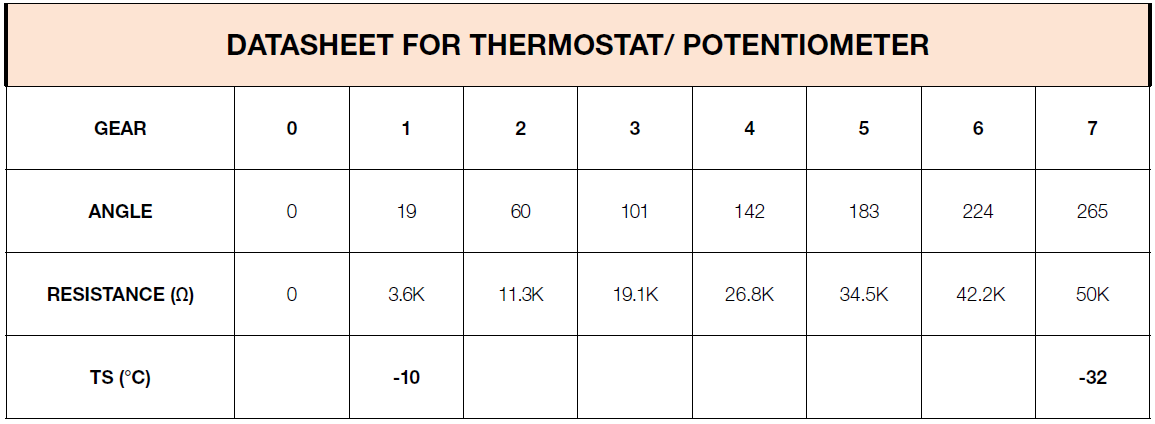
Step 5
Set potentiometer from max to min.
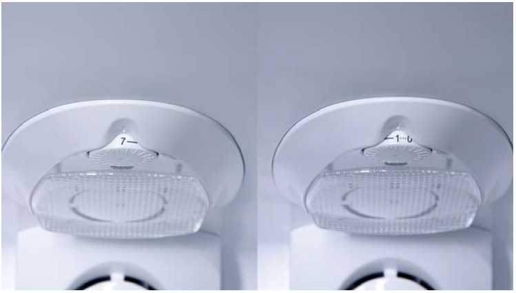
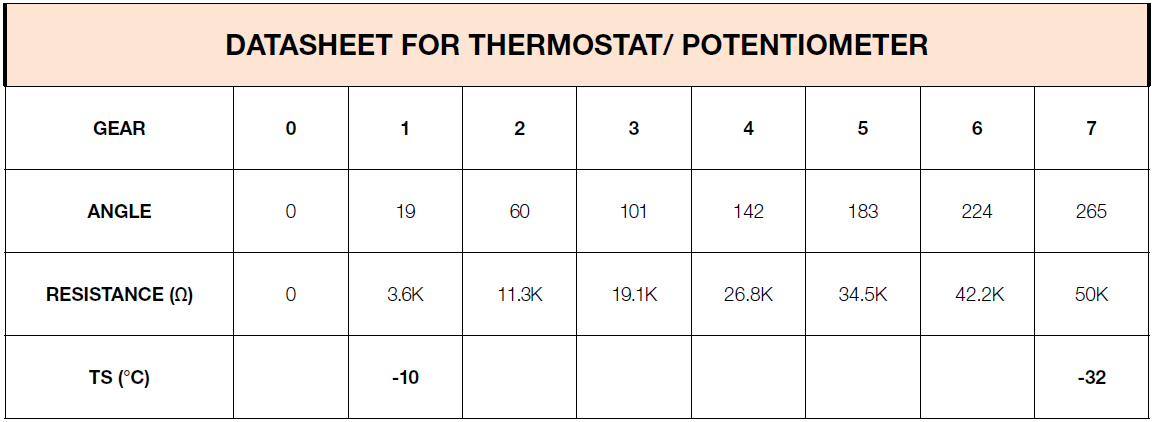
Step 6
Test resistance of potentiometer at each
gear from terminal in PCB area.


CHECK AND TEST 2
Step 1
After removing foam from terminal and reinserting the terminal, please re-test resistance of potentiometer from terminal in PCB area.


Step 1
Lever LED cover off.
Step 2
Remove LED cover.
Step 3
Unscrew potentiometer cover.

Step 4
Remove cover from cavity.
Step 5
Disconnect terminal for potentiometer.
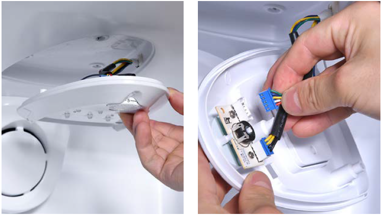
Step 6
Disconnect terminal of LED.
Step 7
Unscrew.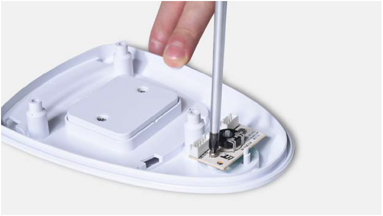
Step 8
Take the potentiometer away.

CHECK AND TEST 3
Step 1
Test potentiometer.


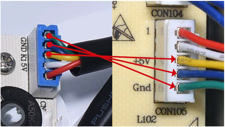
CHECK AND TEST 4
Step 1
Check the connection of wires in foam.


GO BACK TO CHOOSE YOUR MANUAL