

CHECK AND TEST 1
Step 1
Unscrew.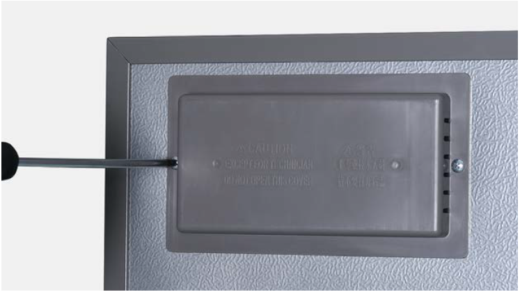
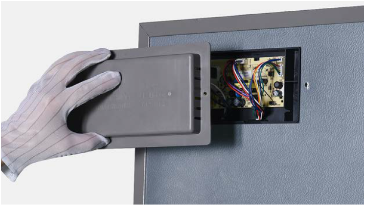
Step 2
Remove the mainboard cover.
Step 3
Check if terminal is loose, full of foam.

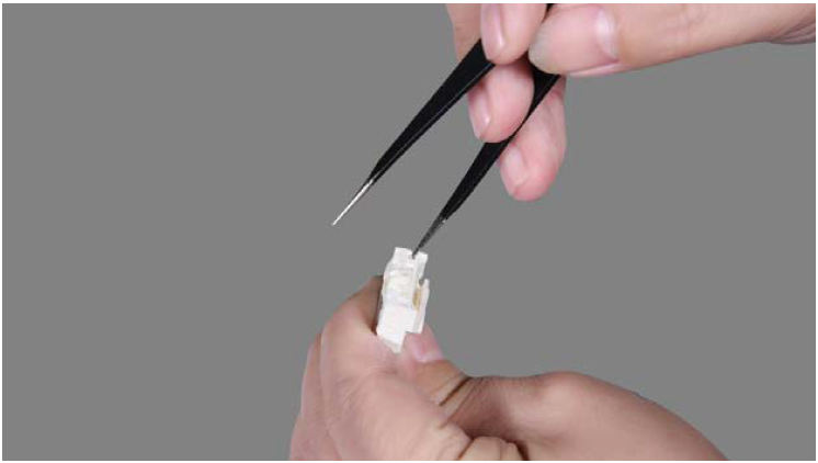
Step 4
If loose, reinsert the terminal.
If terminal is full of foam, use tweezers to remove foam.
Step 5
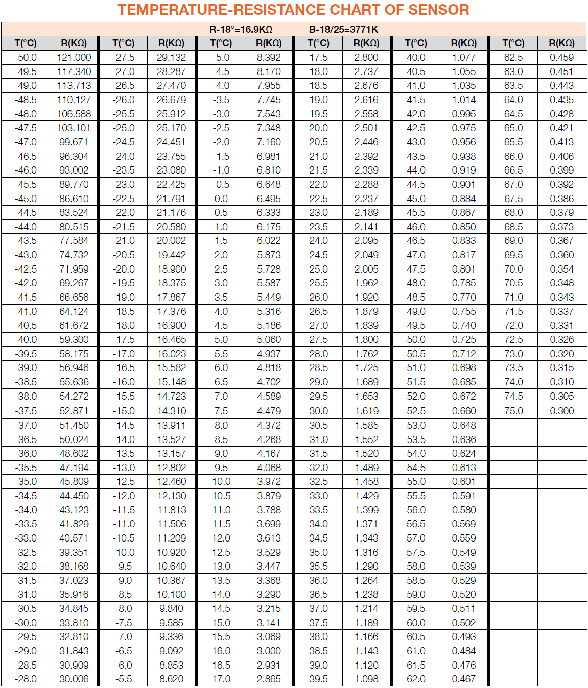
Test resistance of sensor from terminal in PCB area.

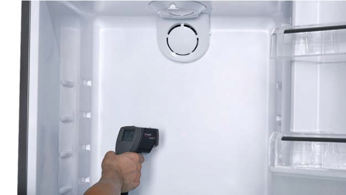
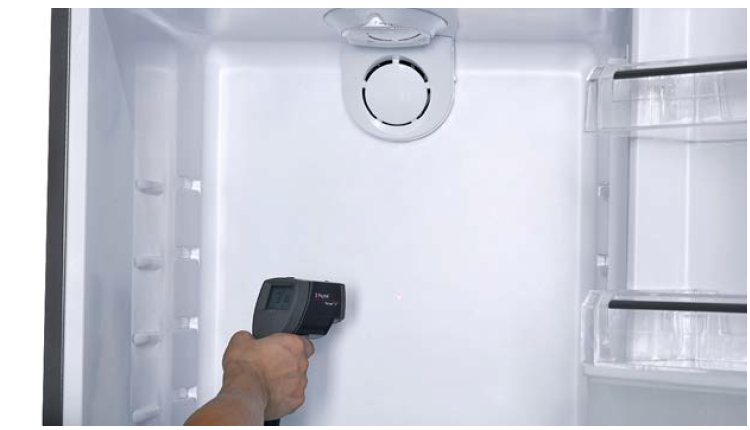
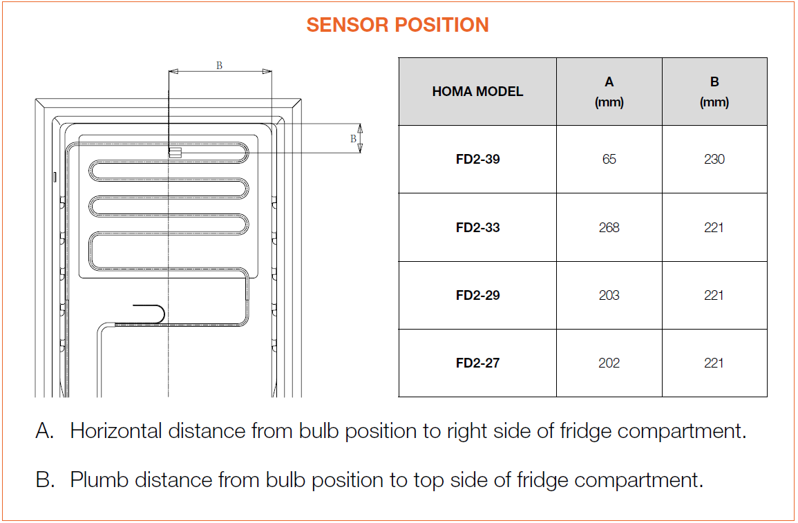
Step 6
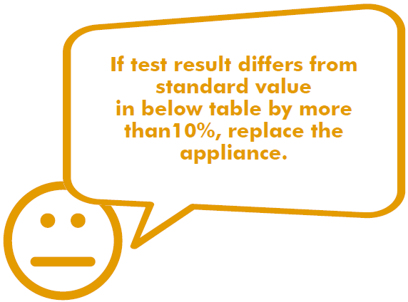
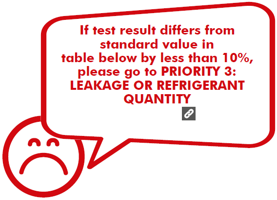
Follow below table to find out sensor position and measure temperature of sensor position.


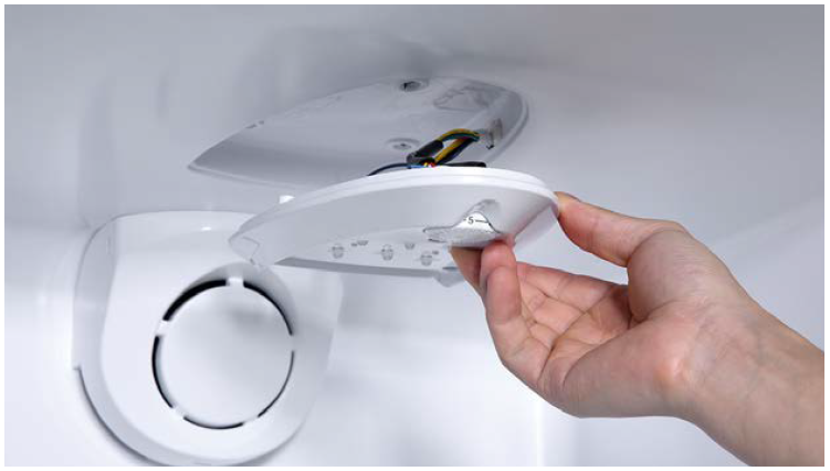
Step 1
Lever LED cover off.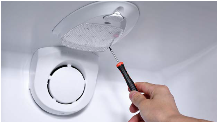
Step 2
Remove LED cover.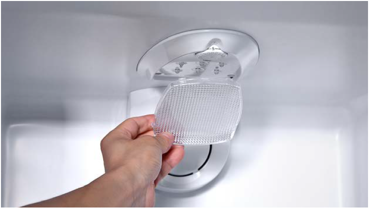
Step 3
Unscrew potentiometer cover.
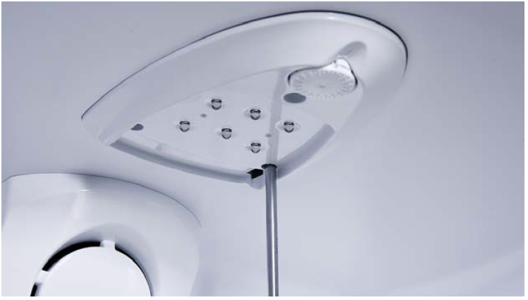
Step 4
Remove cover from cavity.
Step 5
Disconnect terminal for potentiometer.
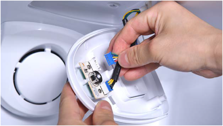
Step 6
Disconnect terminal of LED.

Step 7
Unscrew.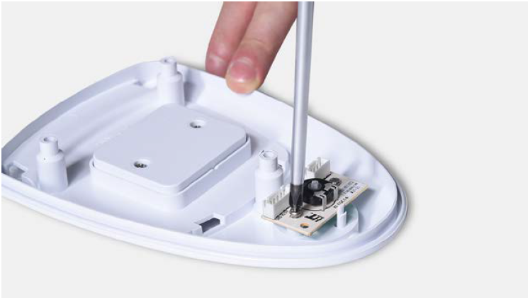
Step 8
Take the potentiometer away.
CHECK AND TEST 2
Step 1
Check if terminal of potentiometer is loose or
full of foam after removing plastic cover from cavity.

Step 2
If loose, reinsert the terminal. If terminal is full of foam, use tweezers to remove.

Step 3
After reinserting the terminal or removing foam
from terminal, please retest resistance of sensor from terminal in PCB area.


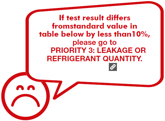
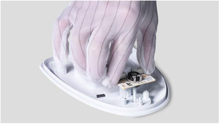
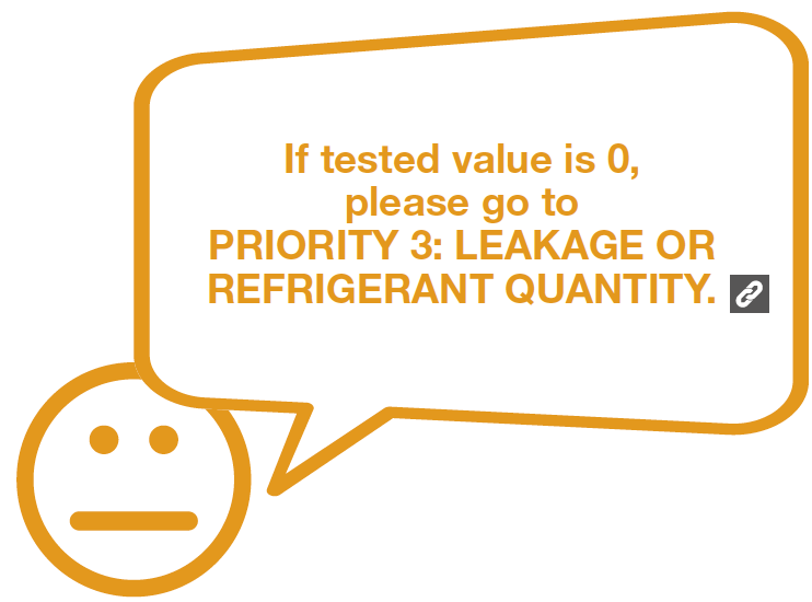
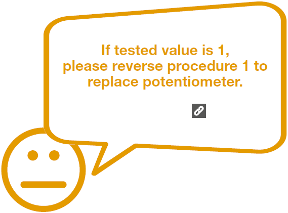
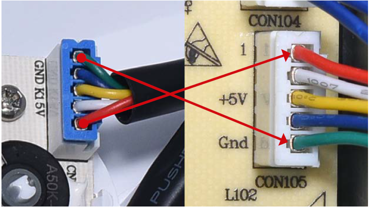
CHECK AND TEST 3
Step 1
Connect 2 pins in red circles, then test the 2 pins indicated by red arrows on potentiometer.


CHECK AND TEST 4
Step 1
Check wire connection in foam from terminal in
PCB area to terminal on potentiometer.


CHECK AND TEST 5
Step 1
Test resistance of sensor from terminal on potentiometer.

Step 2
Follow below table to find out sensor position and measure temperature of sensor position.


GO BACK TO COMPONENT LIST