

CHECK AND TEST 1
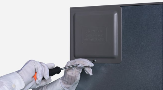
Step 1
Unscrew cover of mainboard with a Cross-head screwdriver.
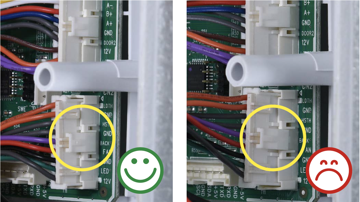
Step 2
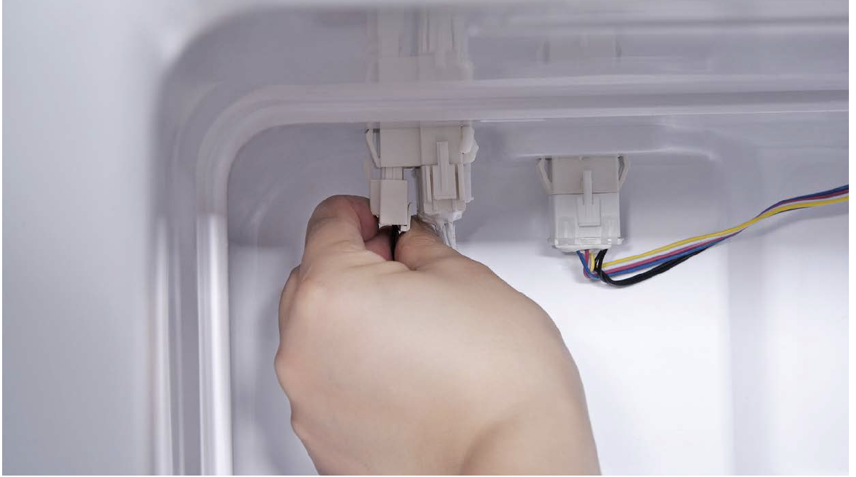
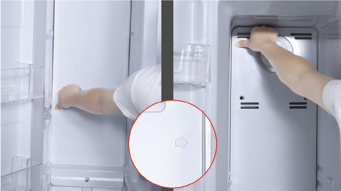
In mainboard area, checkif terminal is inserted to
final position.
If not, reinserted to final
position.
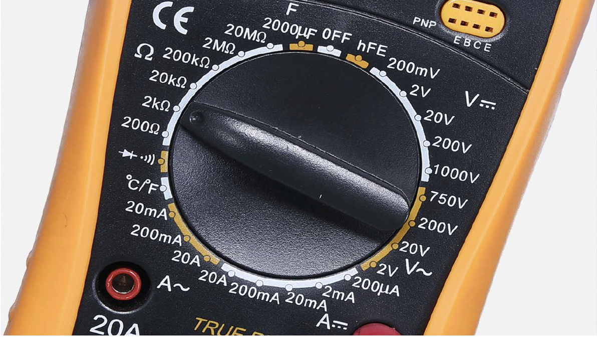
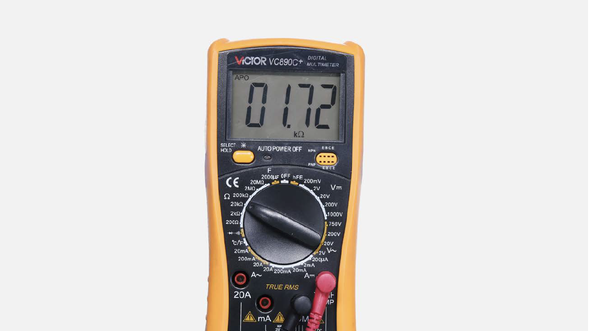
Step 3
Set multimeter to
resistance gear.
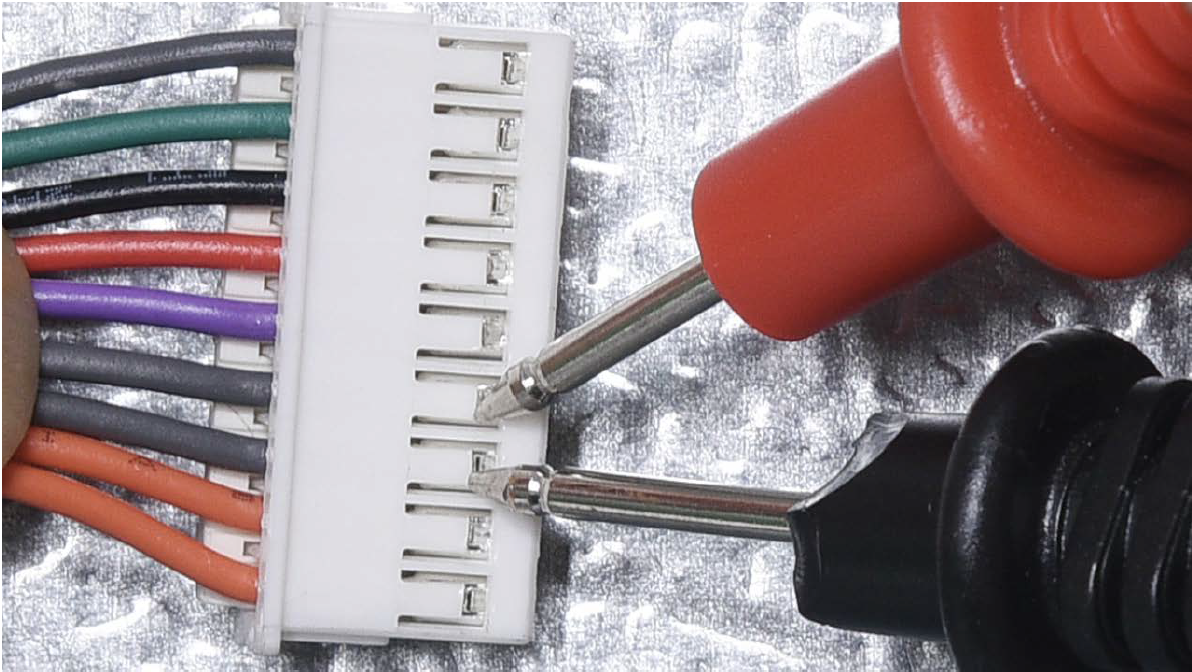
Step 4
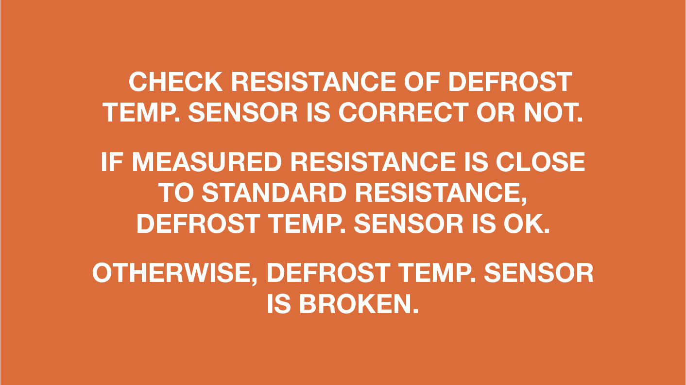
In PCB area, measureresistance of defrost
temp. sensor with a
multimeter.
Step 5
Take note of value.
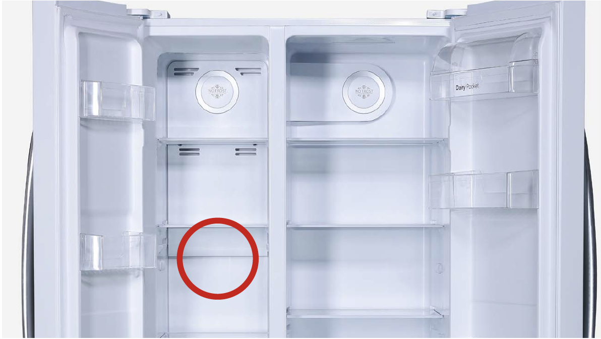
Step 6
Measure the temperature
of freezer air duct, near the
defrost temp. sensor.
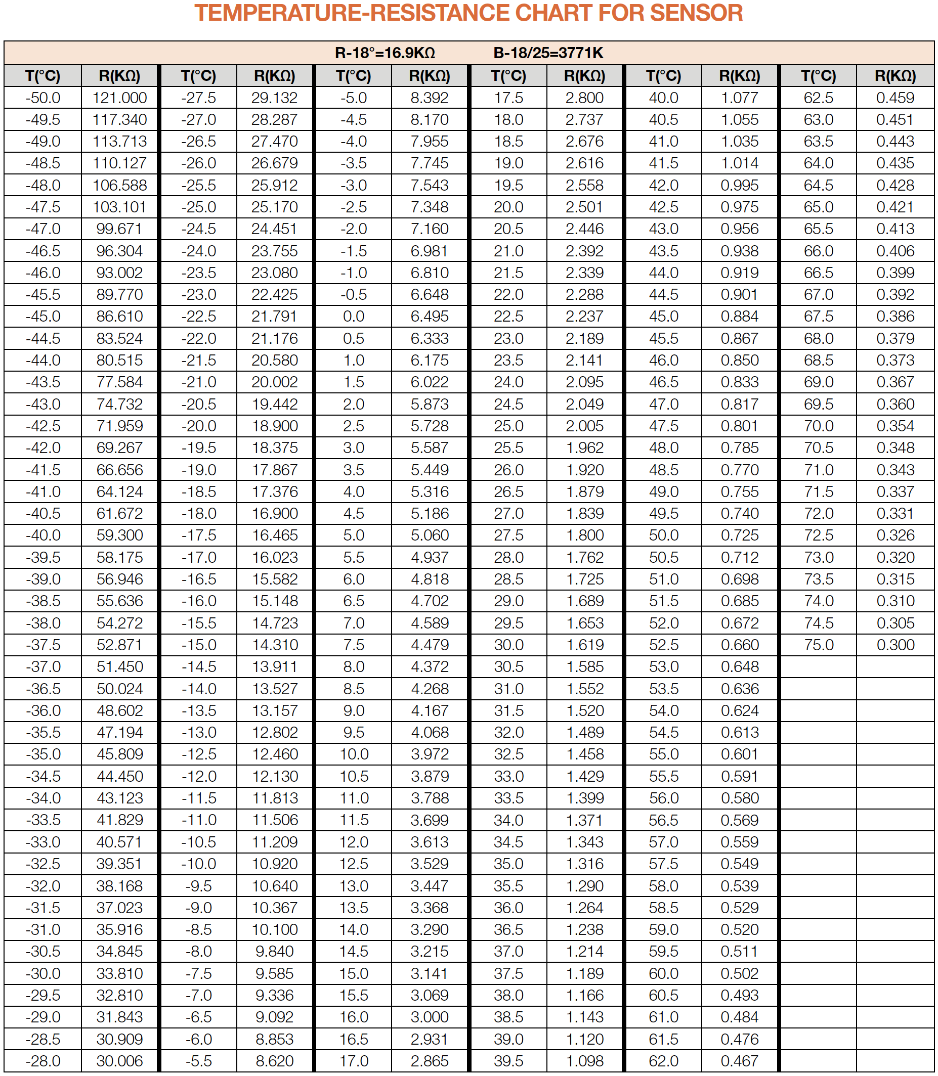
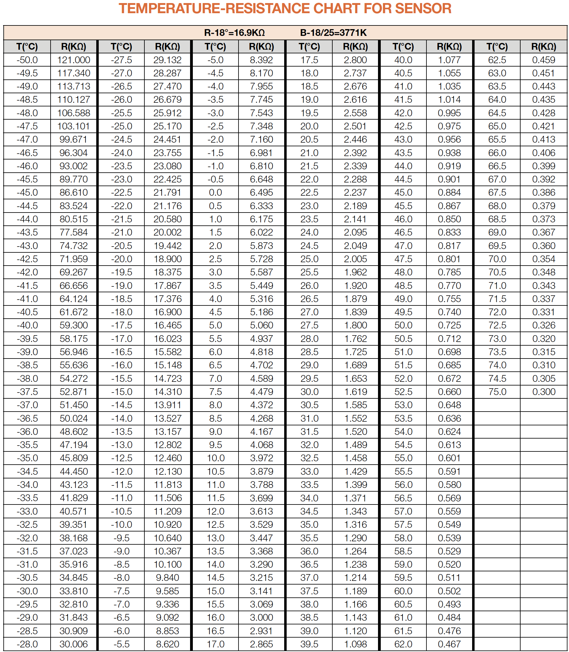
Use measured temperature
to find the standard
resistance value in
Temperature-Resistance
Chart for Sensor.

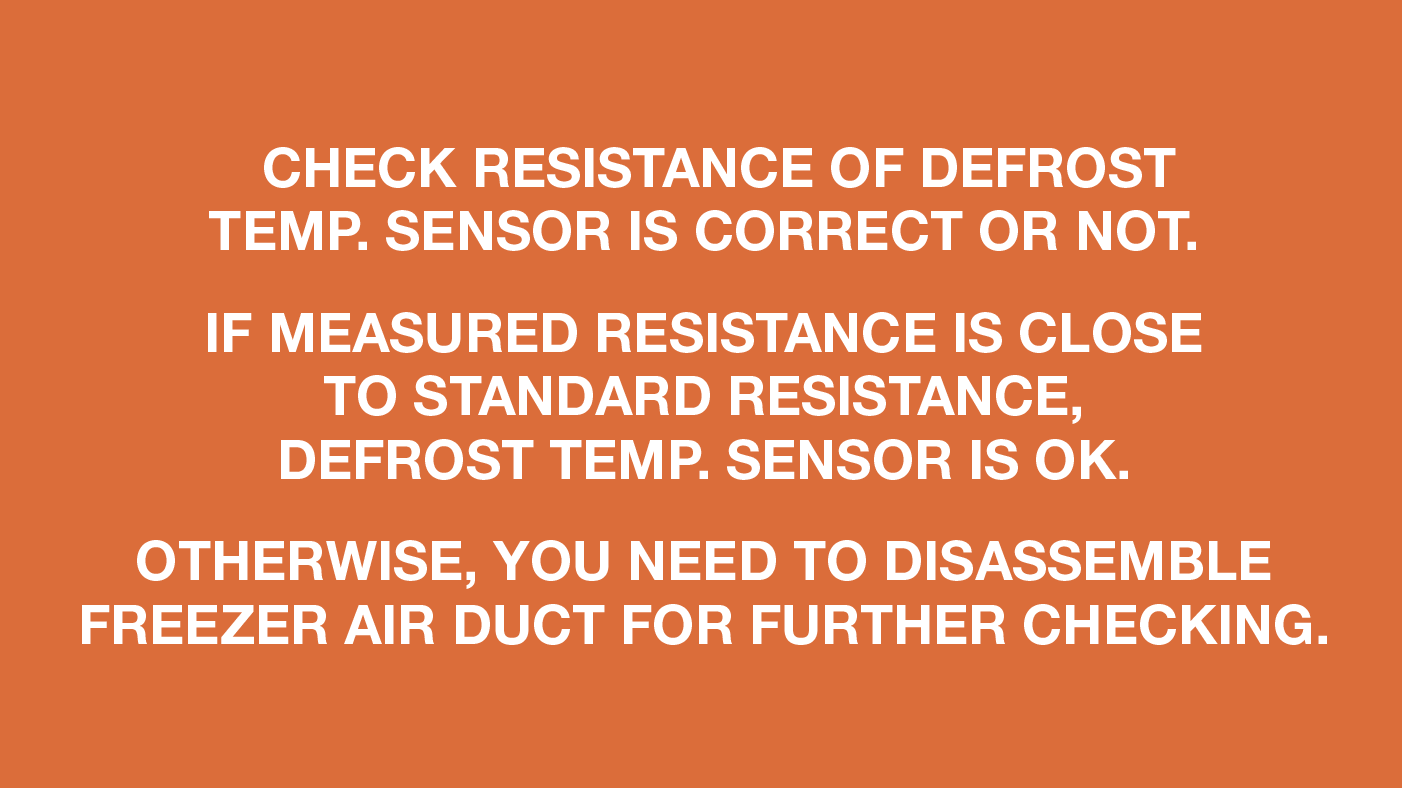
DIAGNOSIS 1


PROCEDURE 1
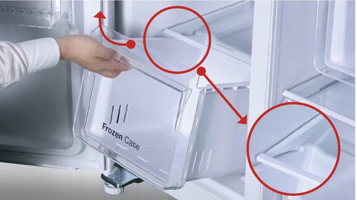
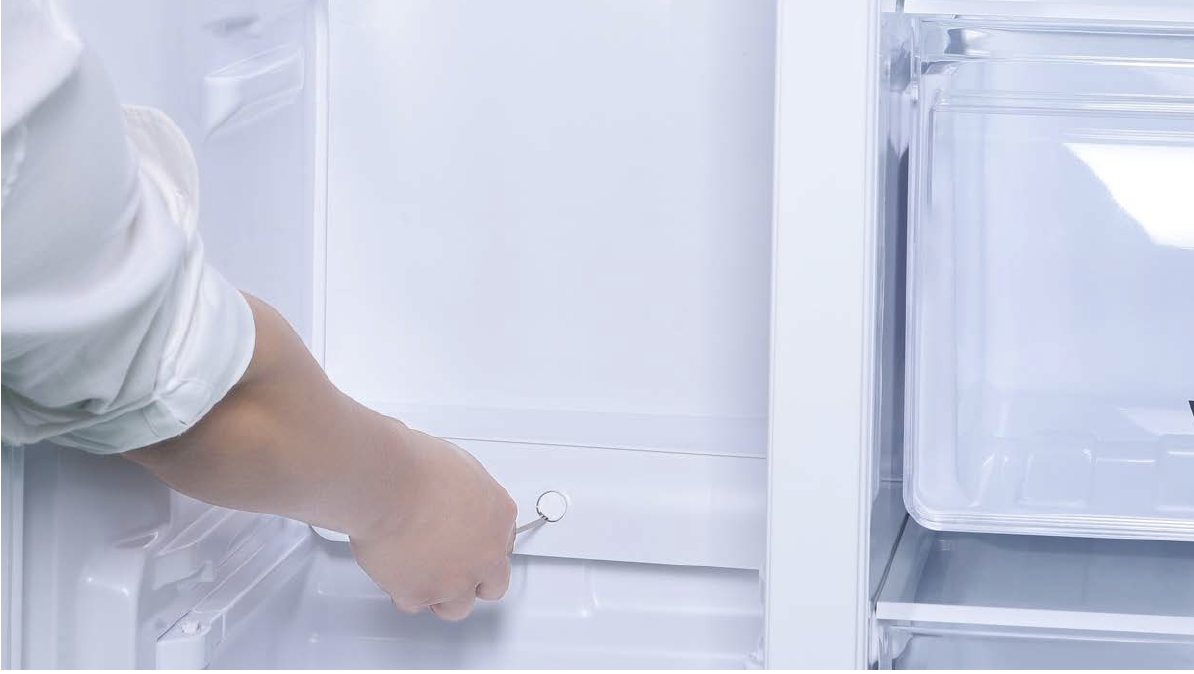
Step 1
Remove all freezer
drawers.
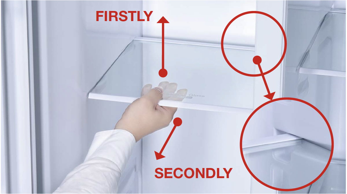
Step 2
shelves.
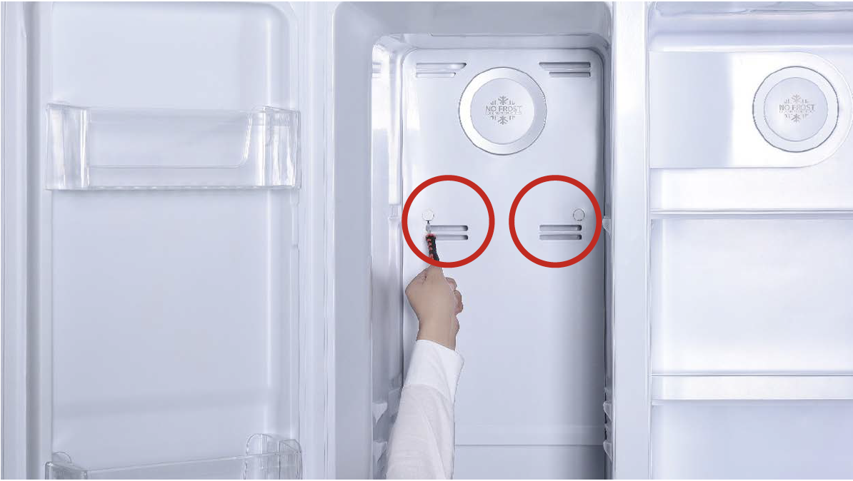
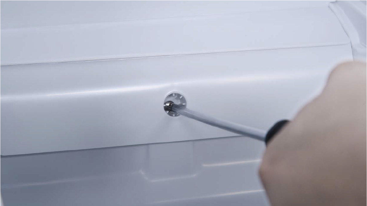
Step 3
Remove screw covers
(total of two) on upper
freezer air duct with
Slotted Screw Driver.
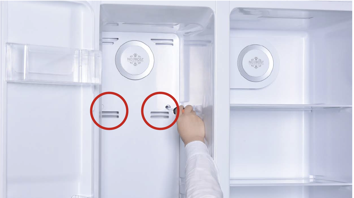
Step 4
Unscrew screws (totalof two) on upper freezer
air duct with Cross-head
screw driver.
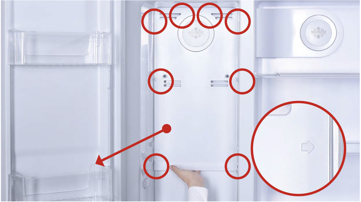
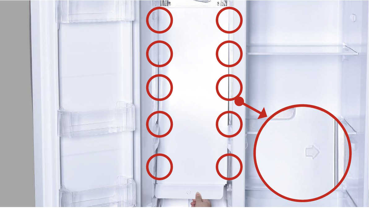
Step 5
Catch bottom of air ductupper freezer air duct
and pull all buckles (total
of 8) down.
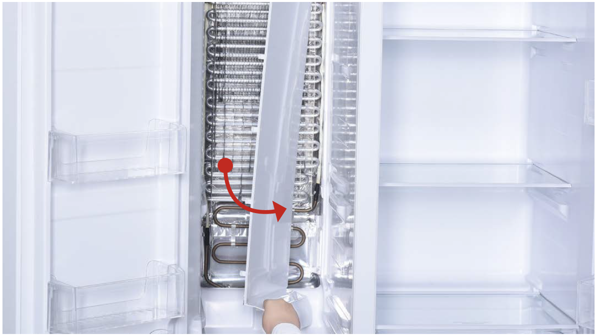
Step 6
Take out upper freezerair duct by tilting to one
side.
Pay attention to the
connectors when pulling
out the air duct.
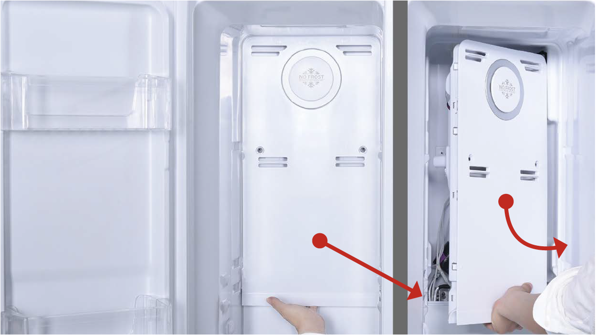
Step 7
Disconnect the terminalfor fan motor and move
upper freezer air duct
away.
Step 8
Remove the screw coveron bottom freezer air
duct with Slotted Screw
Driver.
Step 9
Unscrew the screw onbottom freezer air duct
with Cross-head screw
driver.
Step 10
Catch bottom of air ductbottom freezer air duct
and pull all buckles
(total of 10) down.
Step 11
Take out the lower airduct, tilting to one side.
CHECK AND TEST 2
Step 1
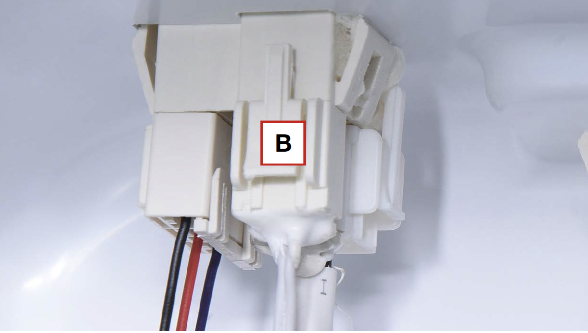
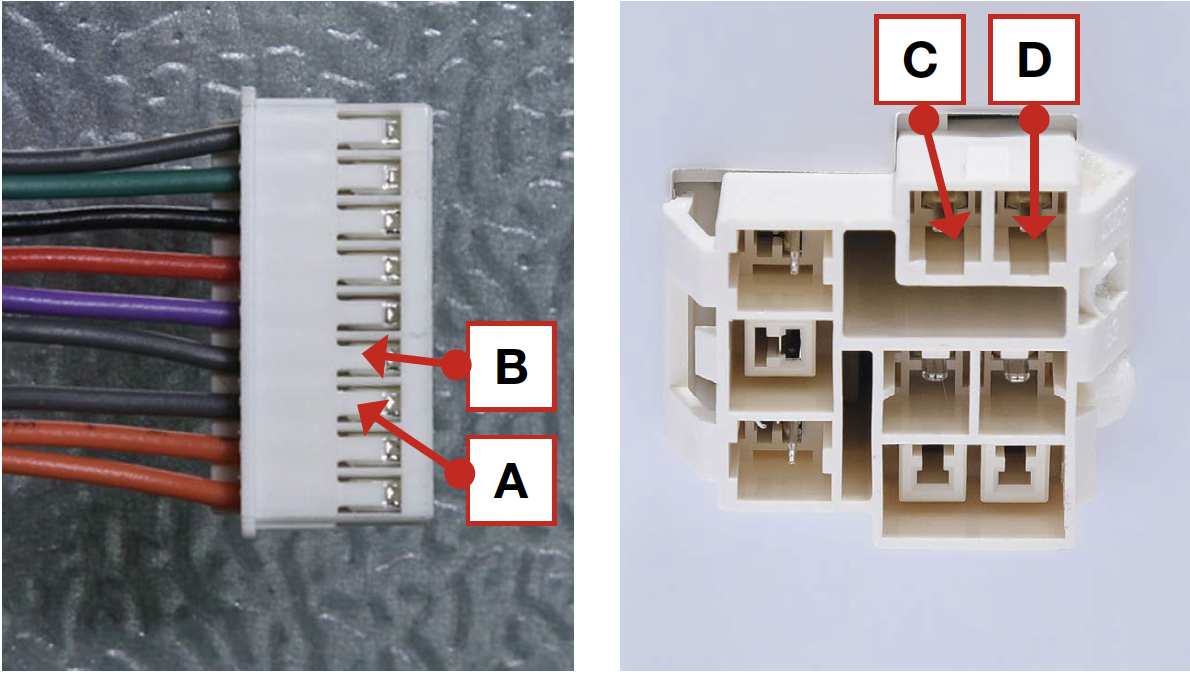
Check if terminal (B) is
inserted to final position.
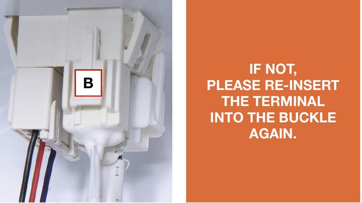
Step 2
Check if terminal (B) isinserted to final position as
showing in picture.
If not, correct it.
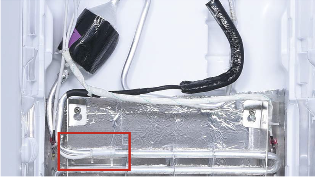
Step 3
Check if wire of defrost
sensor is broken.
If yes, replace it with a
new one.
Step 4
Disconnect terminal ofdefrost temp. sensor (B).
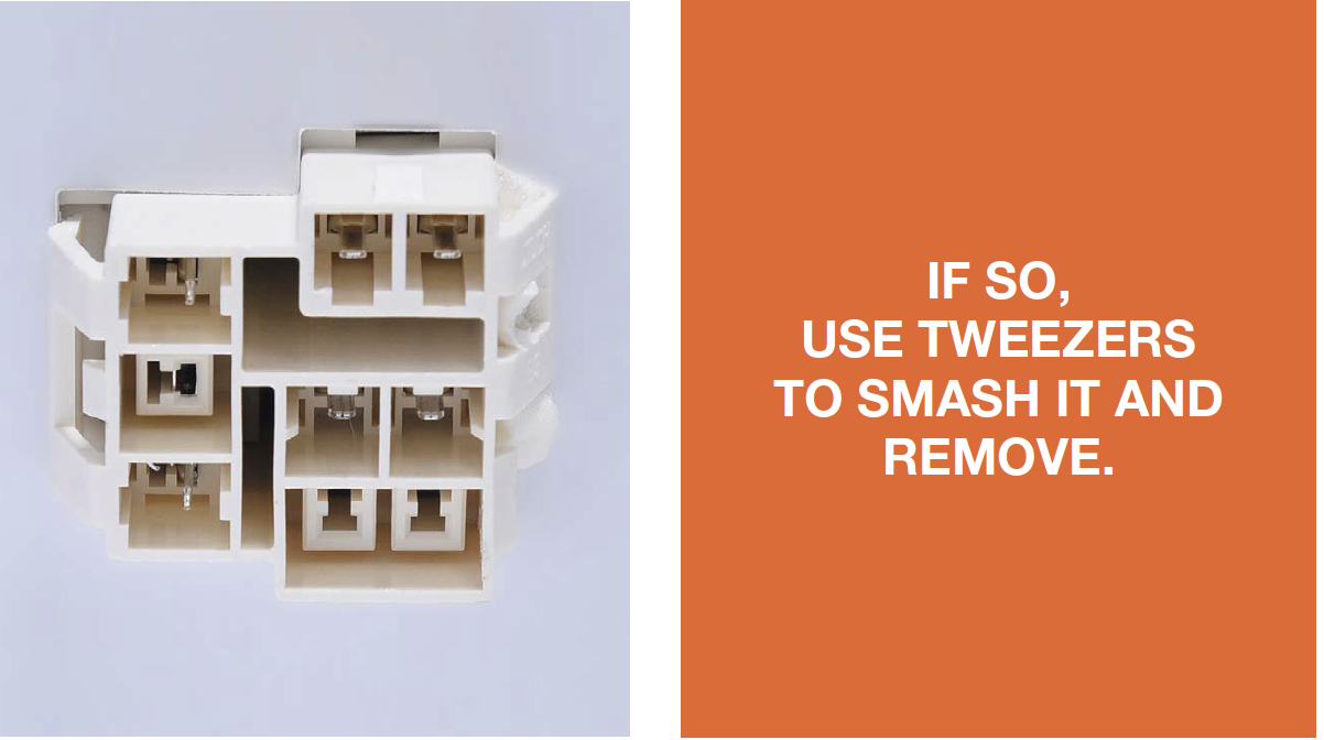
Step 5
Check if the terminal isstuffed with foam.
Step 6
Measure resistance ofdefrost temp. sensor
from terminal in freezer,
and take note of it.
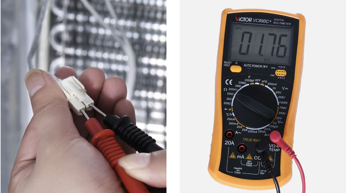
Step 7
Measure the temperatureof defrost temp. sensor.
Use measured
temperature to find the
standard resistance
value in Temperature-
Resistance Chart for
Sensor.
DIAGNOSIS 2

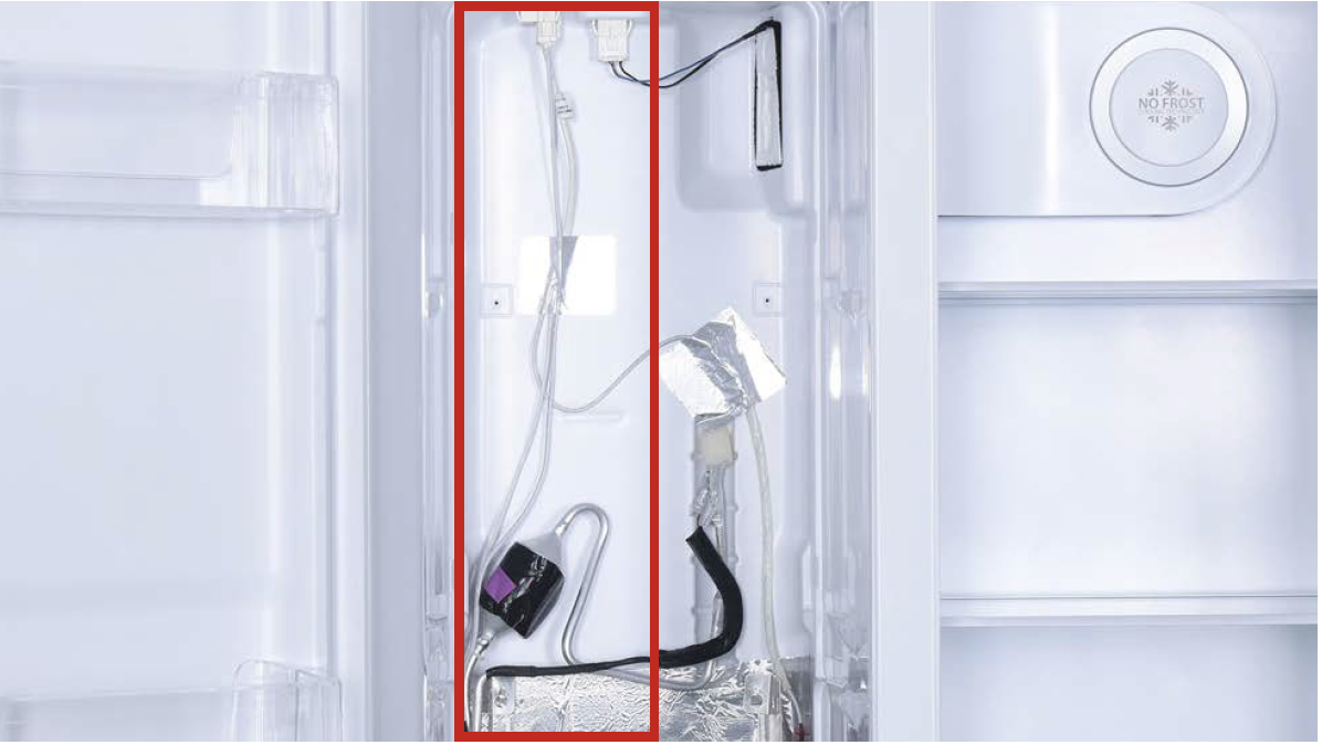
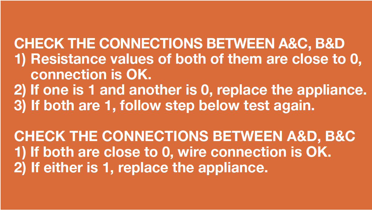
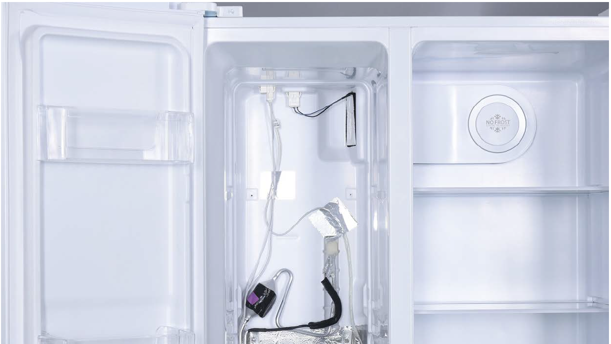
CHECK AND TEST 3
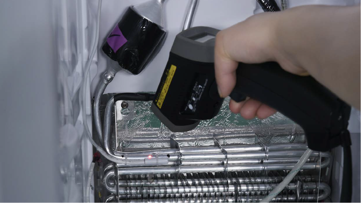
Step 1
Put detector into one
end of wires in PCB area.
Put another detector into
end of wires behind air
duct.
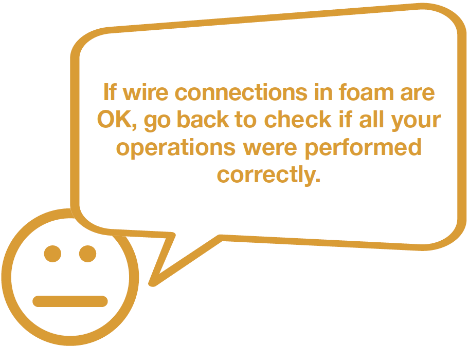
DIAGNOSIS 3


PROCEDURE 2
Tip 1
When restoring the
upper freezer air duct,
fasten the wires to avoid
crushing them with air
duct.
Tip 2
All buckles should bepushed into proper final
position. If not, please
repeat installation.

GO BACK TO COMPONENT LIST