

CHECK AND TEST 1
Step 1
Unscrew cover of
mainboard with a
Cross-head screwdriver.

Step 2
In mainboard area, check
if terminal is inserted to
final position.
If not, reinserted to final
position.

Step 3
Set multimeter toresistance gear.
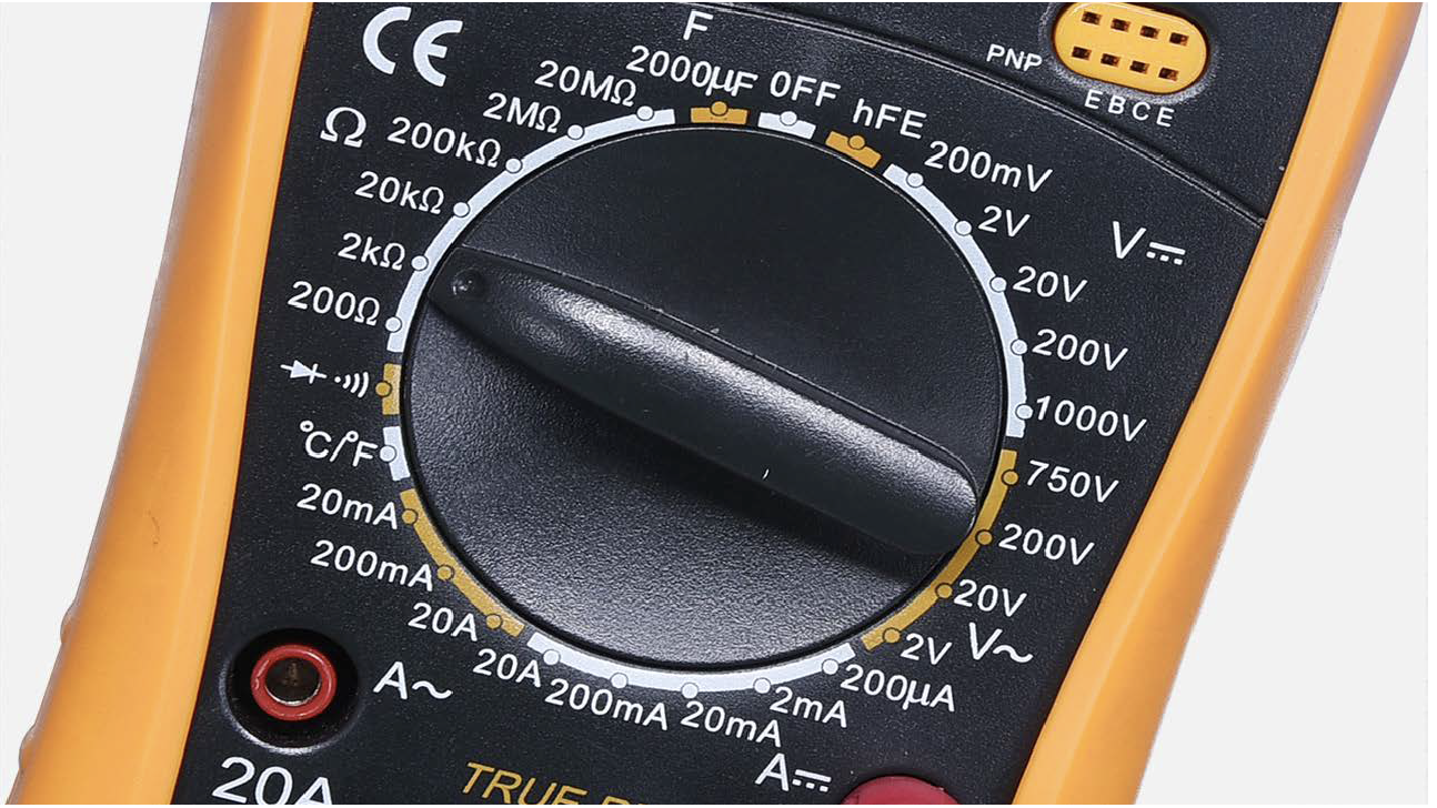
Step 4
Test resistance of sensorfrom terminal in PCB
area.

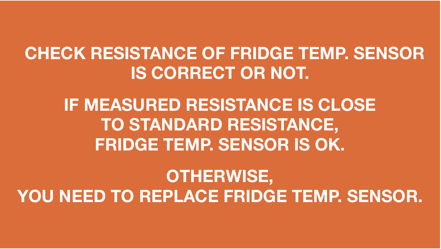
Step 5
Take note of value.

Step 6
Measure the temperature
of fridge temp. sensor.
Find out standard
resistance of fridge
temperature sensor
under measured
temperature in
Resistance Chart for
Sensor.


DIAGNOSIS 1
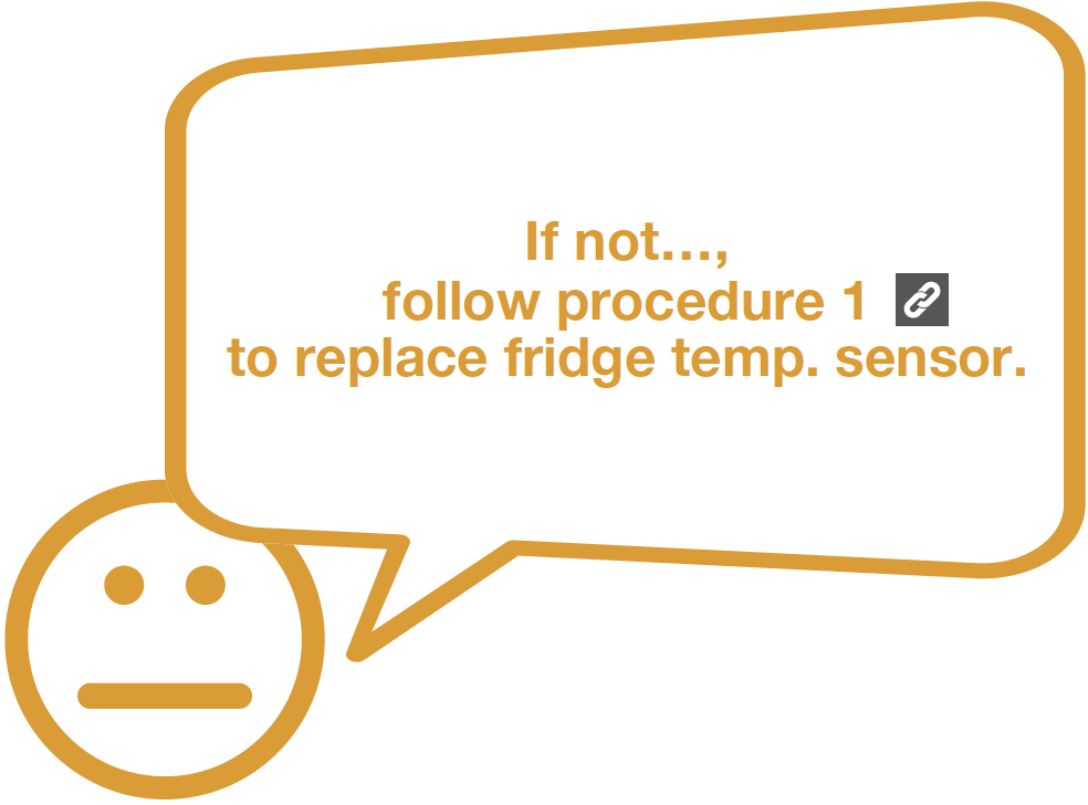


PROCEDURE 1
Step 1
Remove temp. sensor
cover.

Step 2
Cut down the head oftemp. sensor.

Step 3
Prepare a new temp.sensor and cut down the
head.
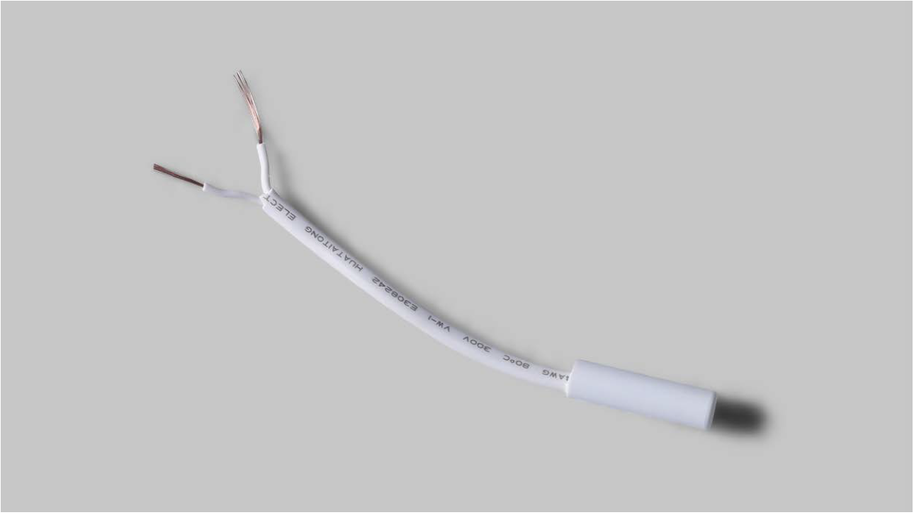
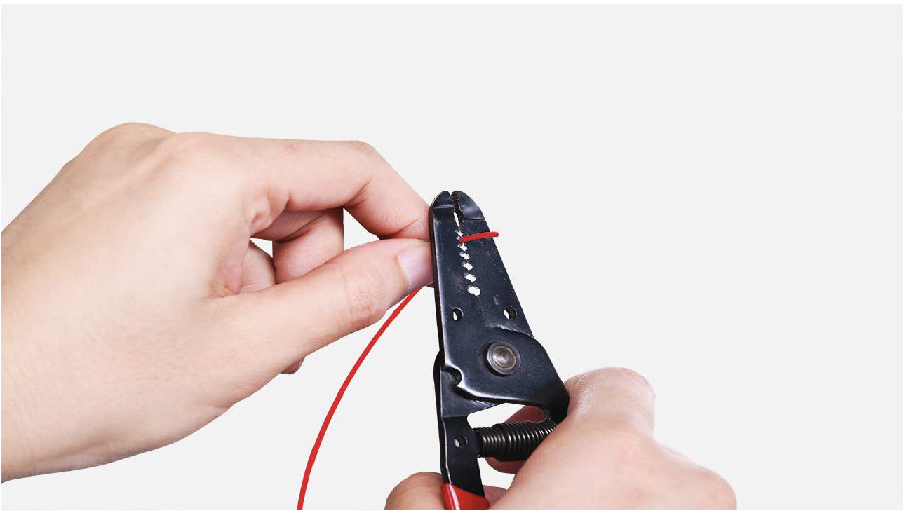
Step 4
Peel off the sleeves.
Step 4
Peel off the sleeves.
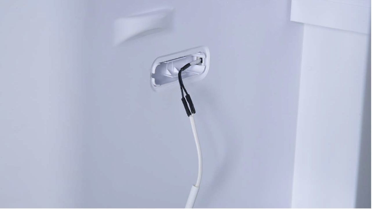
Step 5
Check to ensure proper
wire order and reconnect
them.
Step 5
Check to ensure proper
wire order and reconnect
them.

Step 7
Tin soldering.
Step 8
Cover connecting pointwith electrical tape.
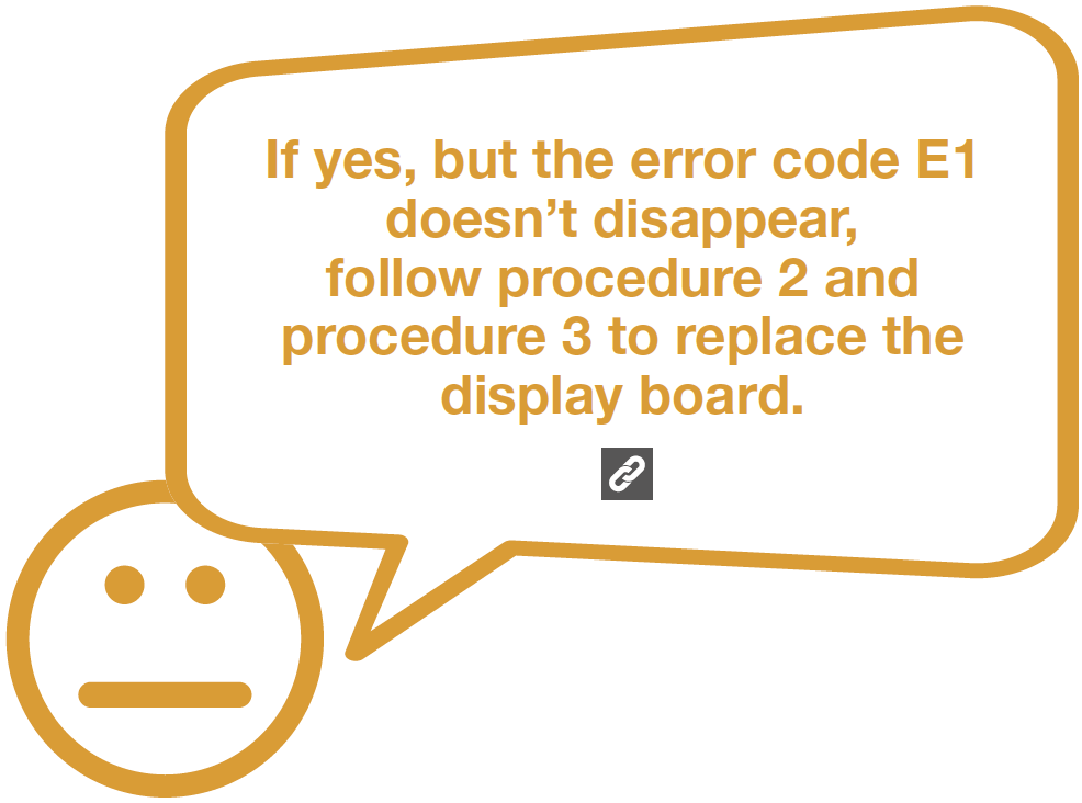
CHECK AND TEST 2


CASE 1:
METAL DOOR

PROCEDURE 2
Step 1
Push a 6mm suckeronto display and turn
the knob to strengthen
suction force.

Step 2
Attach strap to knob
to facilitate pulling out
display board.


Tip 1
After connecting
terminal, please tape
wires in place to prevent
crushing by the cover.

Tip 2
After inserting displayinto cavity, press edge
until you hear a clicking
sound, this means the
board is pushed properly
into final position.
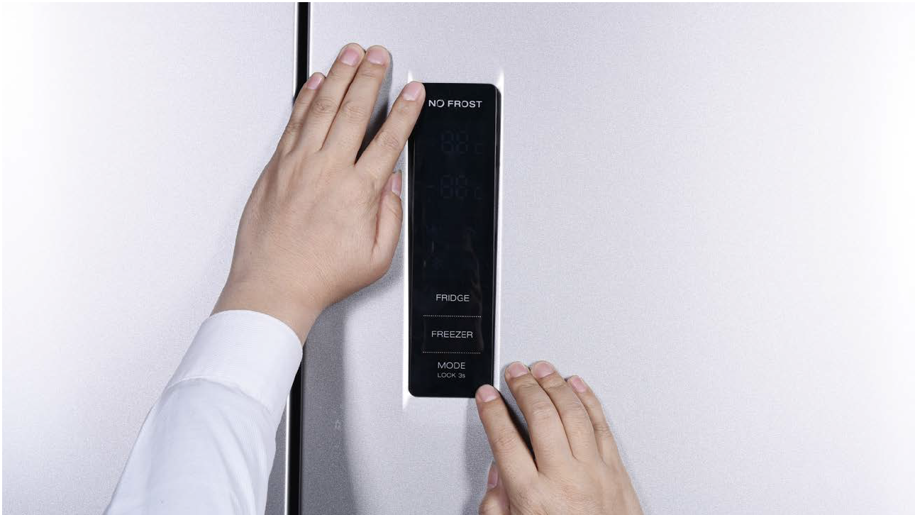
Please press all
buttons on display
board to make sure
display functions
properly.
CASE 2:
GLASS DOOR

PROCEDURE 2

Step 1
Lever off the cover ondoor cap.

Step 2
Remove the screws (intotal 2).
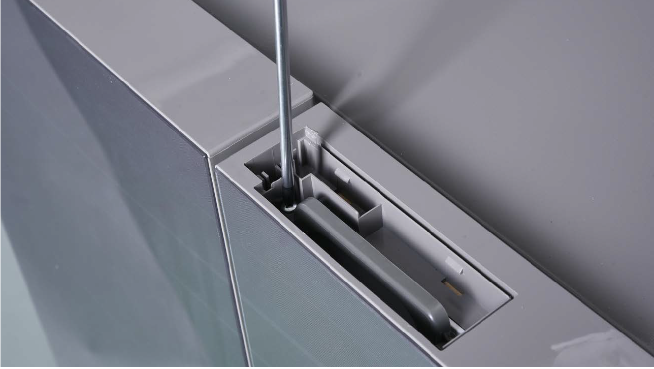
Step 3
Pull out the plastic;
Step 4
Disconnect the terminal
for display panel.

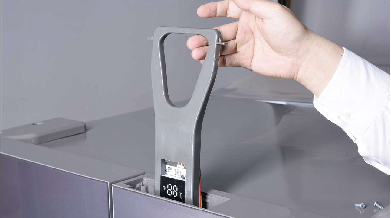
Step 5
Remove tape.
Step 6
Push display out by the
corner.


PROCEDURE 3
Tip 1
Please press all buttonson display board to verify
if it is working properly.
Make sure all words and
icons are clear.

Tip 2
If not clear, disassembleand put tape on points
indicated by red circles.

CHECK AND TEST 3


PROCEDURE 4

Step 1
Unscrew cover ofmainboard with a
Cross-head screwdriver.

Step 2
Disconnect terminals.
Step 3
Prize off earthing wires.
Step 4
Unscrew the mainboard.
Step 5
Prize off the buckle toremove mainboard.


PROCEDURE 5

CHECK AND TEST 4


CHECK AND TEST 5


GO BACK TO COMPONENT LIST