

CHECK AND TEST 1
Step 1
Unscrew cover of
mainboard with a
Cross-head screwdriver.

Step 2
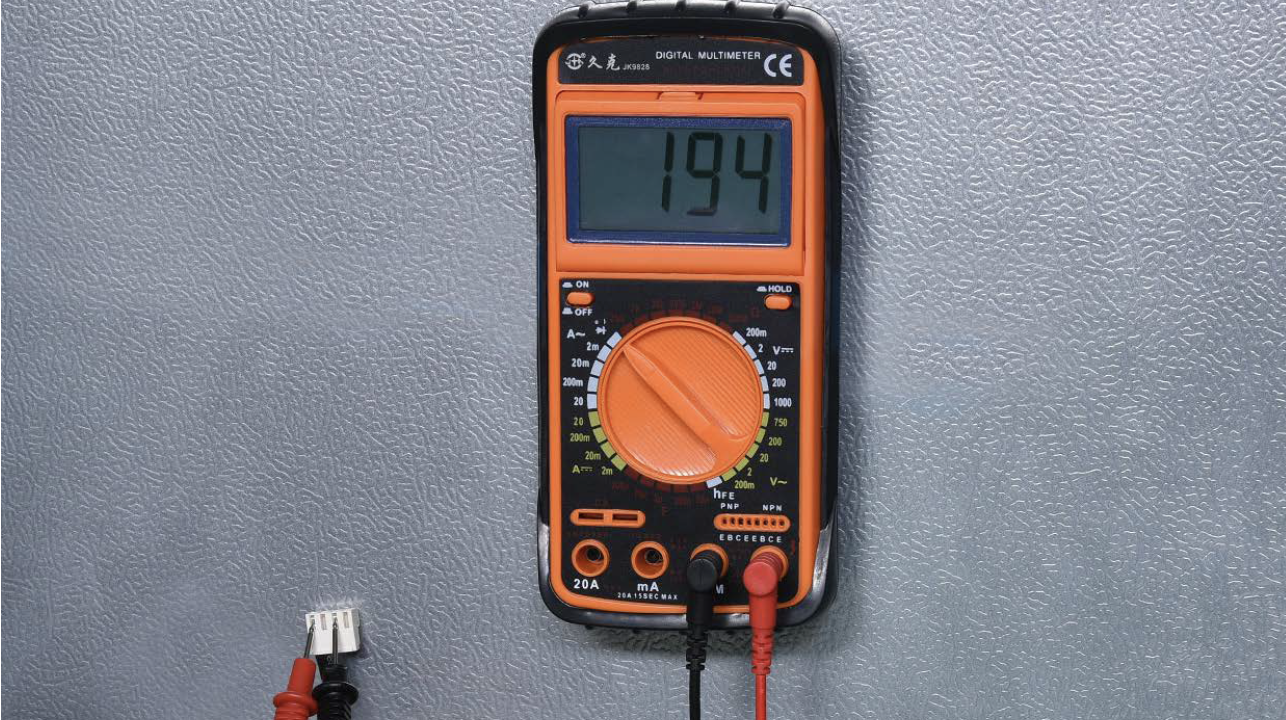
Measure resistance of
heater from terminal in
PCB area.

Step 3
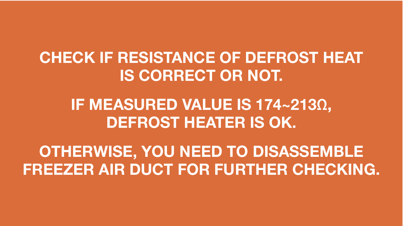
Check the result.
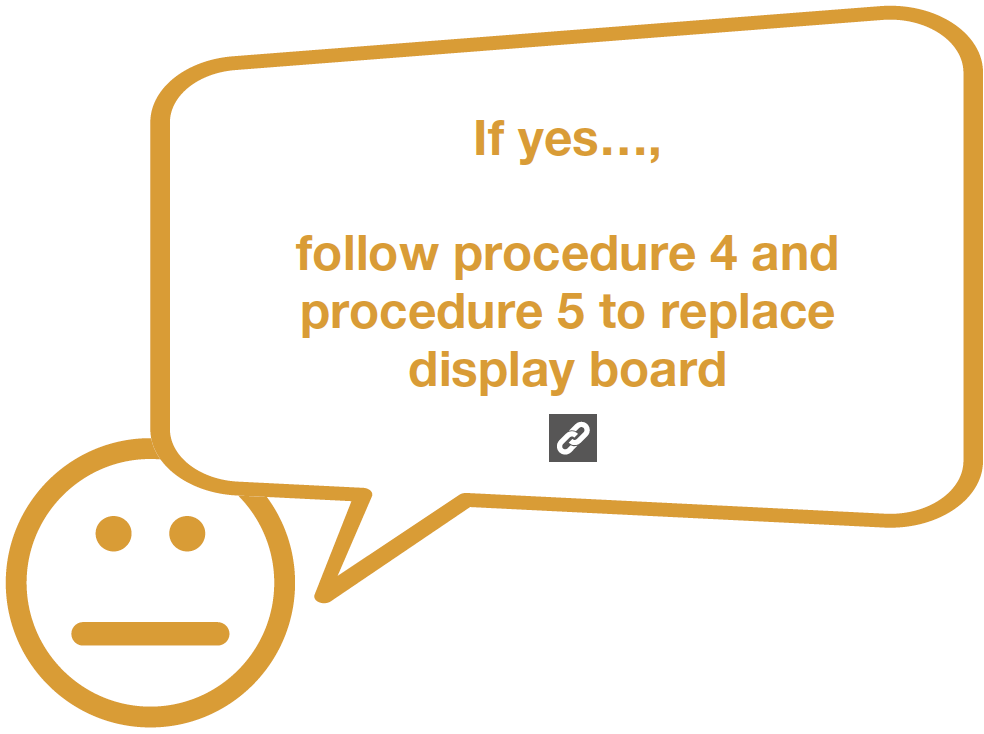
DIAGNOSIS 1
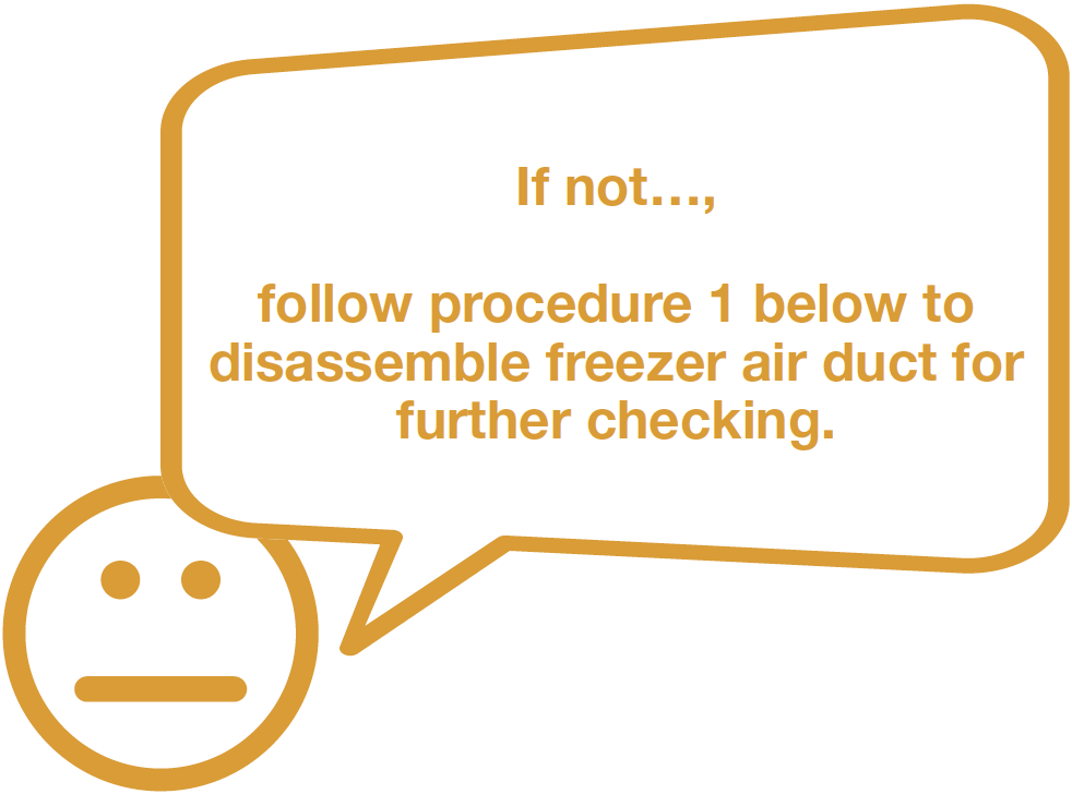

PROCEDURE 1
Step 1
Remove all freezerdrawers.

Step 2
Remove all freezer shelves.
Step 3
Remove screw covers(total of two) on upper
freezer air duct with
Slotted Screw Driver.

Step 4
Unscrew screws (total of two) on upper freezerair duct with Cross-head screw driver.

Step 5
Catch bottom of air ductupper freezer air duct
and pull all buckles (total
of 8) down.

Step 6
Take out upper freezer air duct by tilting to oneside.
Pay attention to the connectors when pulling
out the air duct.

Step 7
Disconnect the terminal for fan motor and move upper freezer air ductaway.

Step 8
Disconnect the terminal for fan motor and move upper freezer air ductaway.

Step 9
Unscrew the screw on bottom freezer air ductwith Cross-head screw driver.

Step 10
Catch bottom of air duct bottom freezer air duct and pull all buckles(total of 10) down.

Step 11
Take out the lower airduct, tilting to one side.


CHECK AND TEST 2
Step 1
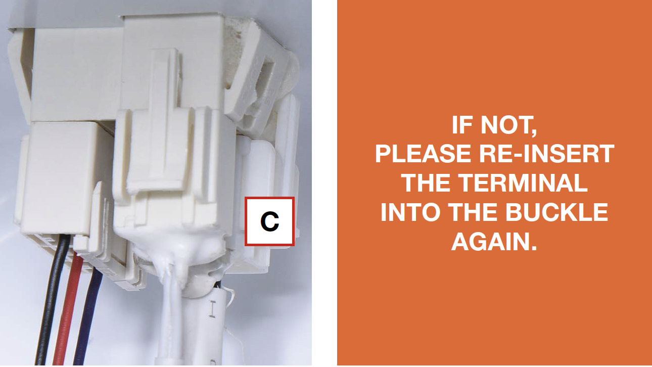
Check if terminal (C) isinserted to final position.
If not, re-insert it.
Step 2
Disconnect the terminal for defrost heater.
Step 3
Check if the terminal is filled with foam.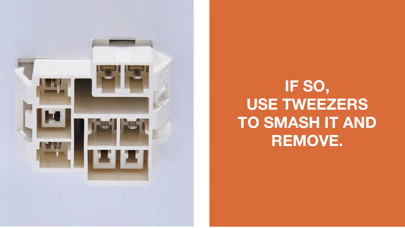
Step 4
Measure the resistance of heater from terminalin freezer.

Step 5
Assess the result.
DIAGNOSIS 2


PROCEDURE 2

Step 1
Use screwdriver to remove the heat conductor (if any).
Step 2
Use 6mm cross-head screwdriver to unscrewthe defrost heater.

Step 3
Cut off the fastening straps.
Step 4
Tear off Polyethylene sealing foam.
Step 5
Loosen the fastening clips for heater.
Step 6
Remove the heater, reverse above processto reinstall the new heater.
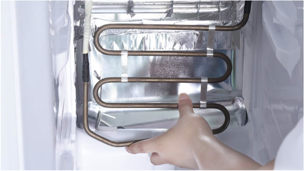
WARNING:
Be careful not to
deform pipes in
red square during
steps 5 and 6.

PROCEDURE 3

Tip 1
Do not injure the wires ofthe heater while installing
the new heater.

CHECK AND TEST 3
Step 1
Set multimeter toresistance gear.

Step 2
Use multimeter to check whether wireconnections in foam are good or not.

DIAGNOSIS 3


CASE 1:
METAL DOOR

PROCEDURE 4

Step 1
Push a 6mm sucker onto display and turnthe knob to strengthen suction force.

Step 2
Attach strap to knob to facilitate pulling outdisplay board.


PROCEDURE 5
Tip 1
After connectingterminal, please tape
wires in place to prevent
crushing by the cover.

Tip 2
After inserting display into cavity, press edgeuntil you hear a clicking sound, this means the
board is pushed properly into final position.
Please press all
buttons on display
board to make sure
display functions
properly.

CASE 2:
GLASS DOOR

PROCEDURE 4

Step 1
Lever off the cover ondoor cap.

Step 2
Remove the screws (intotal 2).

Step 3
Pull out the plastic;
Step 4
Disconnect the terminalfor display panel.

Step 5
Remove tape.
Step 6
Push display out by thecorner.


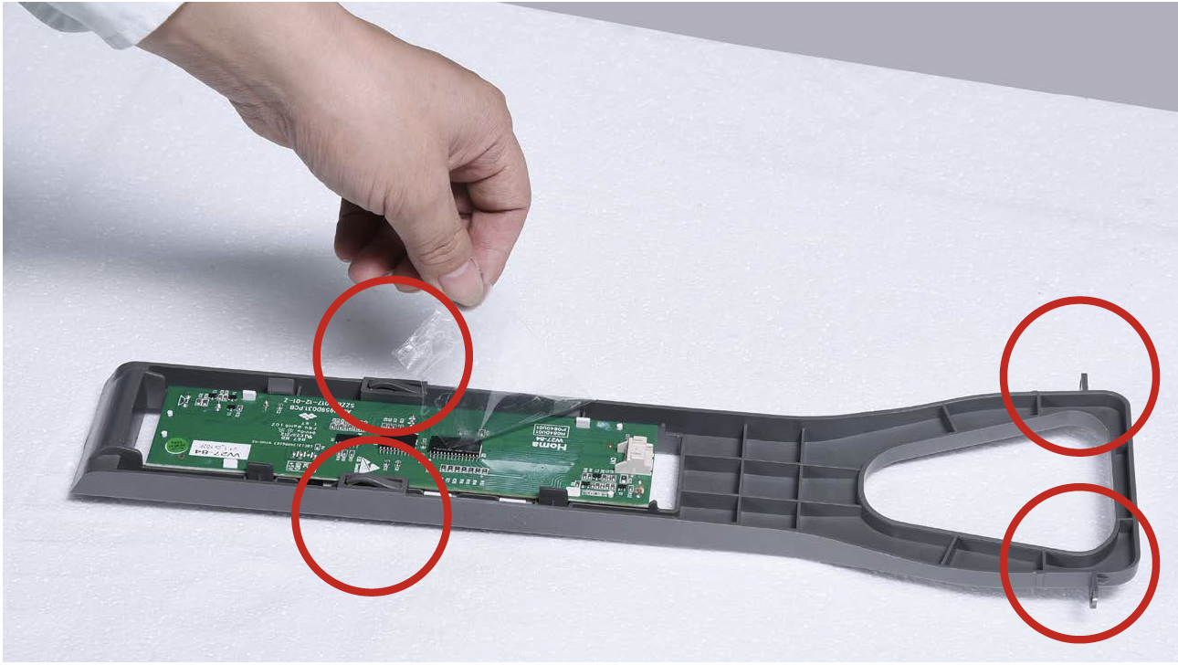
PROCEDURE 5
Tip 1
Please press all buttonson display board to verify
if it is working properly.
Make sure all words and
icons are clear.

Tip 2
If not clear, disassembleand put tape on points
indicated by red circles.
CHECK AND TEST 4


PROCEDURE 4

Step 1
Unscrew cover ofmainboard with a
Cross-head screwdriver.

Step 2
Disconnect terminals.
Step 3
Prize off earthing wires.
Step 4
Unscrew the mainboard.
Step 5
Prize off the buckle toremove mainboard.


PROCEDURE 5
CHECK AND TEST 5


GO BACK TO COMPONENT LIST