

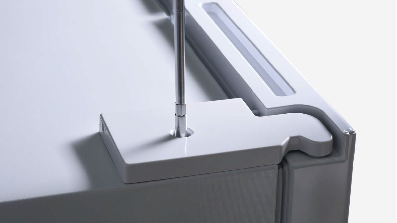
CHECK AND TEST 1
Step 1
Unscrew cover of
mainboard with a
cross-head screwdriver.

Step 2
Check if terminal in PCBarea is inserted to final
position.
If not, reinsert it to final
position.

Step 3
Unscrew hinge cover.
Step 4
Check if terminal in hinge
cover is inserted to final
position.
If not, reinsert it to final
position.


DIAGNOSIS 1
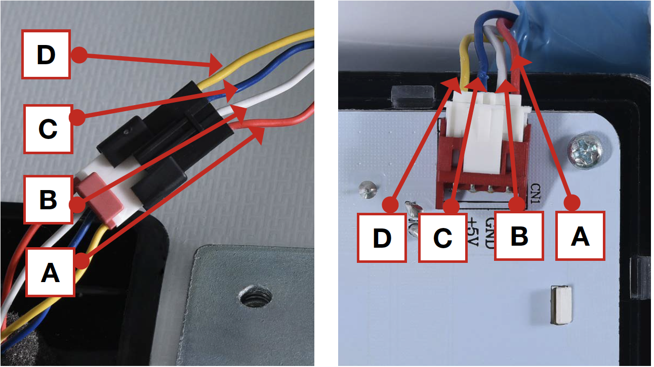
CHECK AND TEST 2
Step 1
Check if wire orders inPCB area and hinge
cover area are correct or
not.
Right picture shows the
correct wire order.

DIAGNOSIS 2

PROCEDURE 1

Step 1
Cut off the wire.
Step 2
Peel off the sleeves.

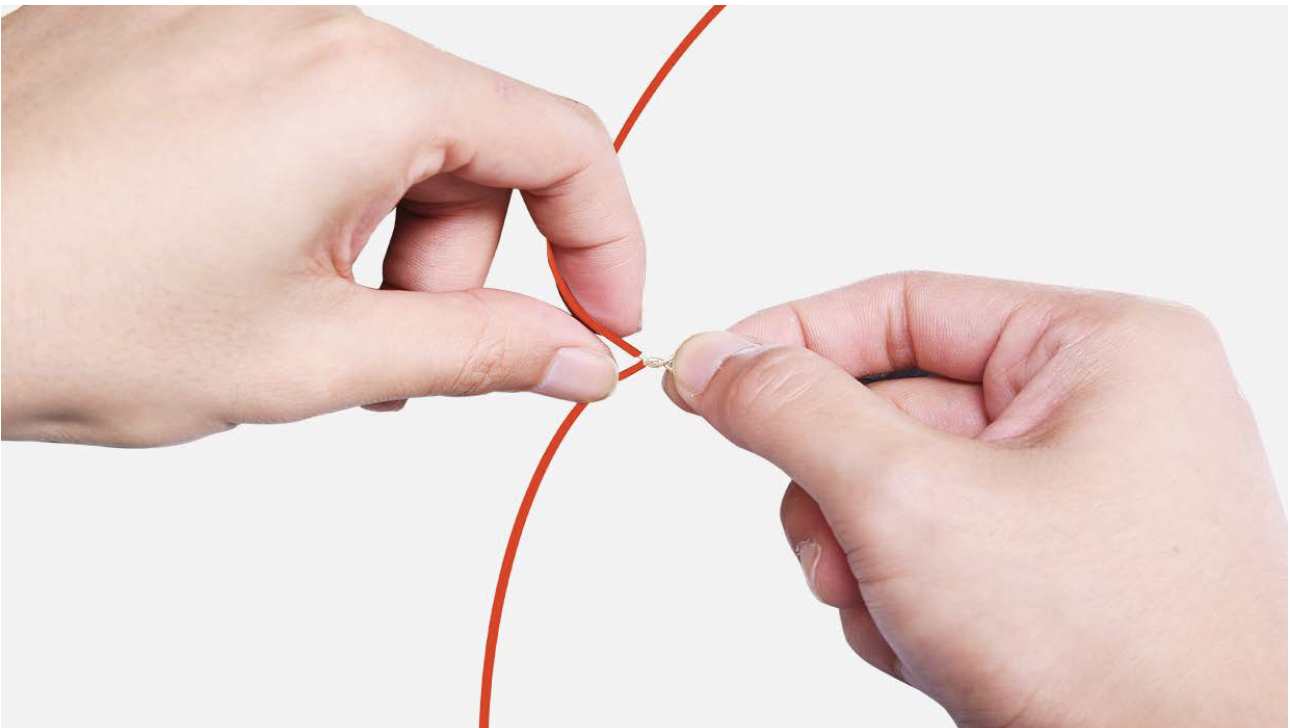
Step 3
Make sure wires arein proper order and
connect them.
Step 4
Tin soldering.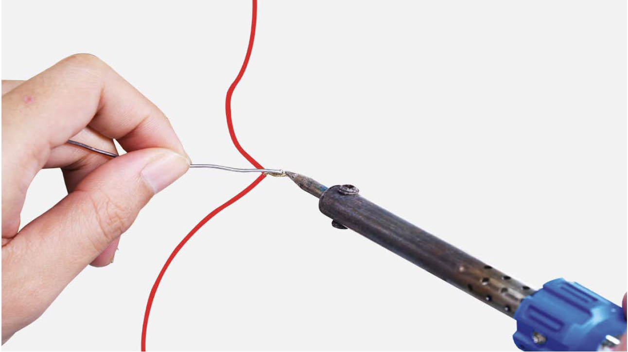
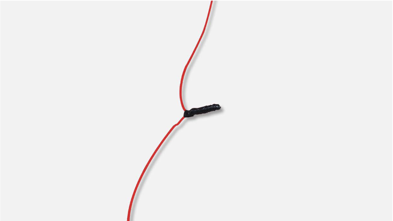
Step 5
Cover connecting point
with electrical tape.
PROCEDURE 2
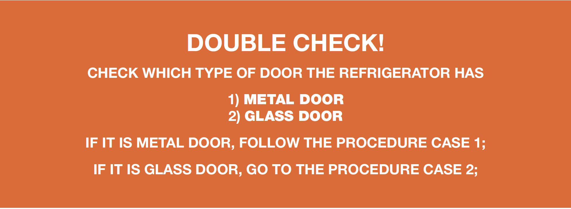
CASE 1:
METAL DOOR
Step 1
Push a 6mm suckeronto display and turn
the knob to strengthen
suction force.

Step 2
Attach strap to knobto facilitate pulling out
display board.

CASE 2:
GLASS DOOR
Step 1
Lever off the cover ondoor cap.
Step 2
Remove the screws (intotal 2).

Step 3
Pull out the plastic;

Step 4
Disconnect the terminalfor display panel.

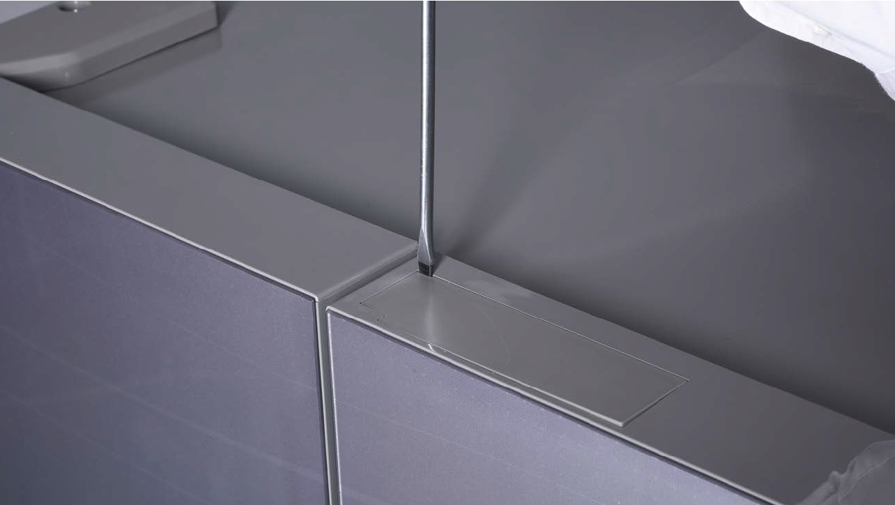
CHECK AND TEST 3
Step 1
Check if connection andwire order in display area
are correct or not.

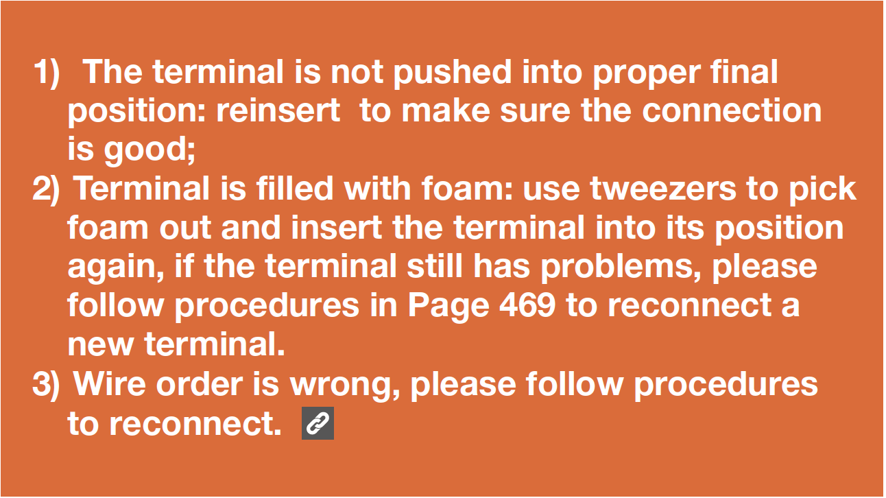
DIAGNOSIS 3

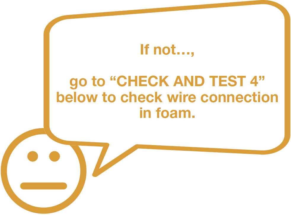
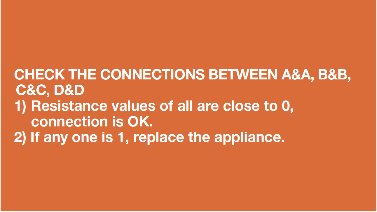
CHECK AND TEST 4
Step 1
Set multimeter to
resistance gear.

Step 2
Check wire connection
from PCB area to hinge
cover area.

Step 3
Check wire connection
from hinge cover area to
display area.
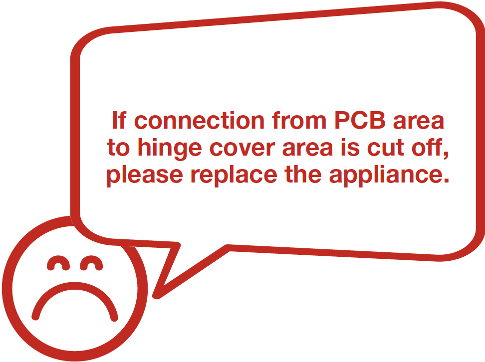
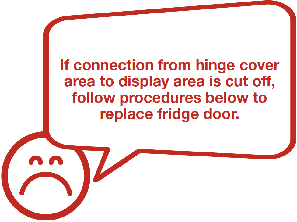
DIAGNOSIS 4

PROCEDURE 3
Step 1
Unscrew hinge cover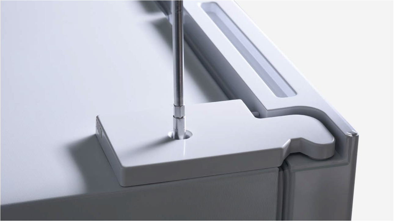
Step 2
Remove the cover.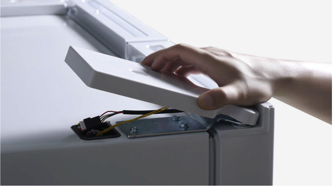
Step 3
Disconnect the terminals.
Step 4
Unscrew 3 bolts andremove the top hinge.
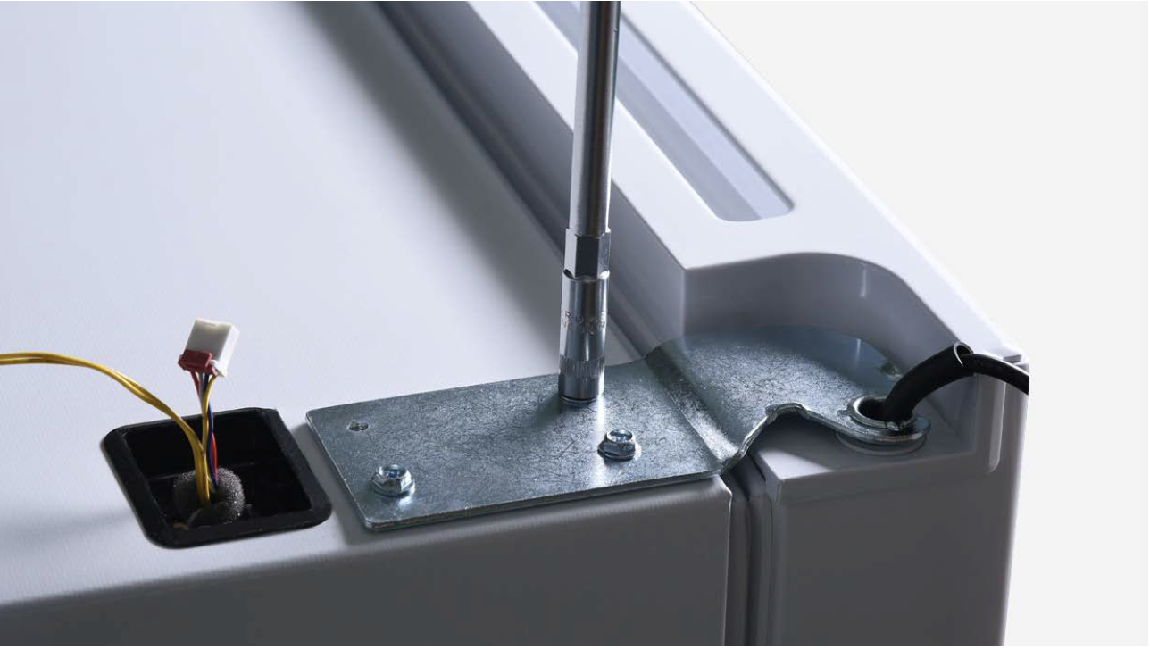
Step 5
Remove the door.
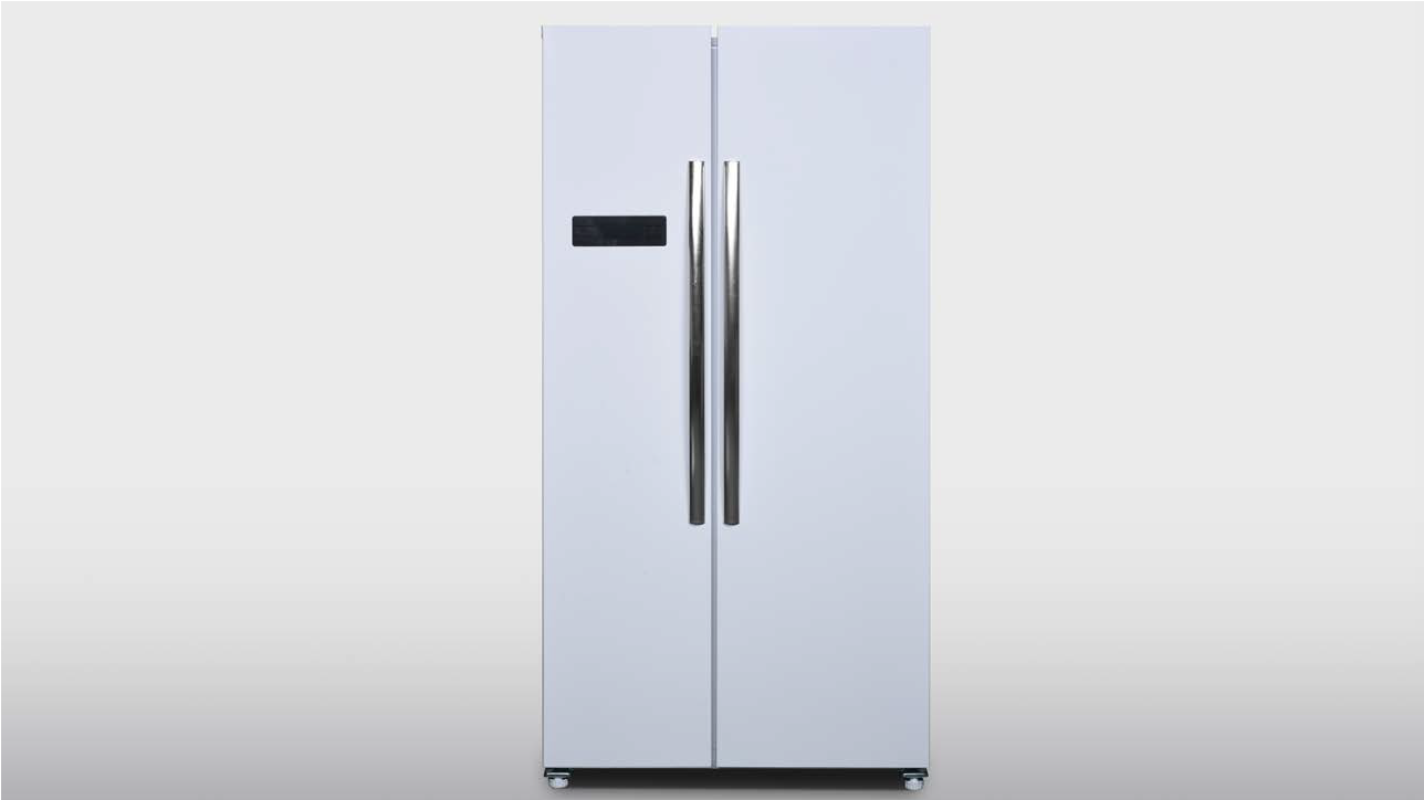
PROCEDURE 4
Tip 1
Make sure gasket isattached well.

Tip 2
Make sure gap betweenfridge door and freezer
door is even.
CHECK AND TEST 5

CHECK AND TEST 6
PROCEDURE 5

Step 1
Unscrew cover ofmainboard with a
Cross-head screwdriver.

Step 2
Disconnect terminals.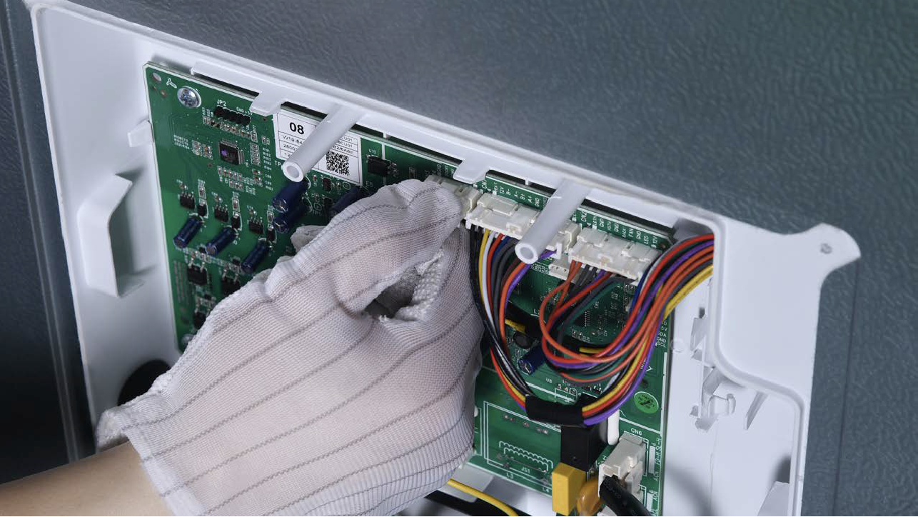
Step 3
Prize off earthing wires.
Step 4
Unscrew the mainboard.
Step 5
Prize off the buckle toremove mainboard.

PROCEDURE 6
CHECK AND TEST 7

GO BACK TO COMPONENT LIST