

CHECK AND TEST 1
Step 1
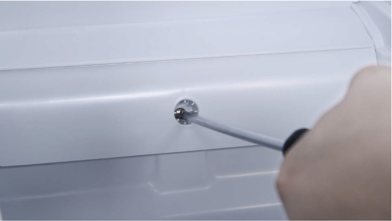
Unscrew cover of mainboard with a Cross-head screwdriver.
Step 2
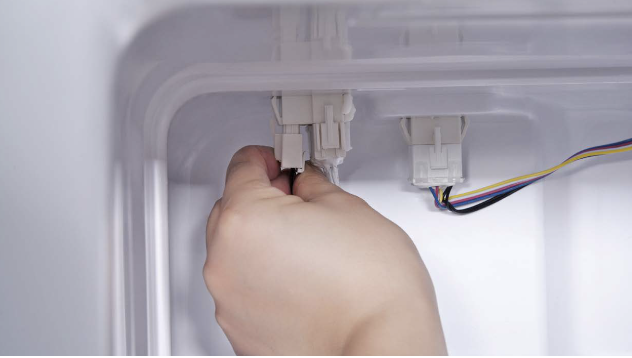
Check if terminal in PCB
area is pushed to final
position.
If not, reinsert it to final
position.

Step 3
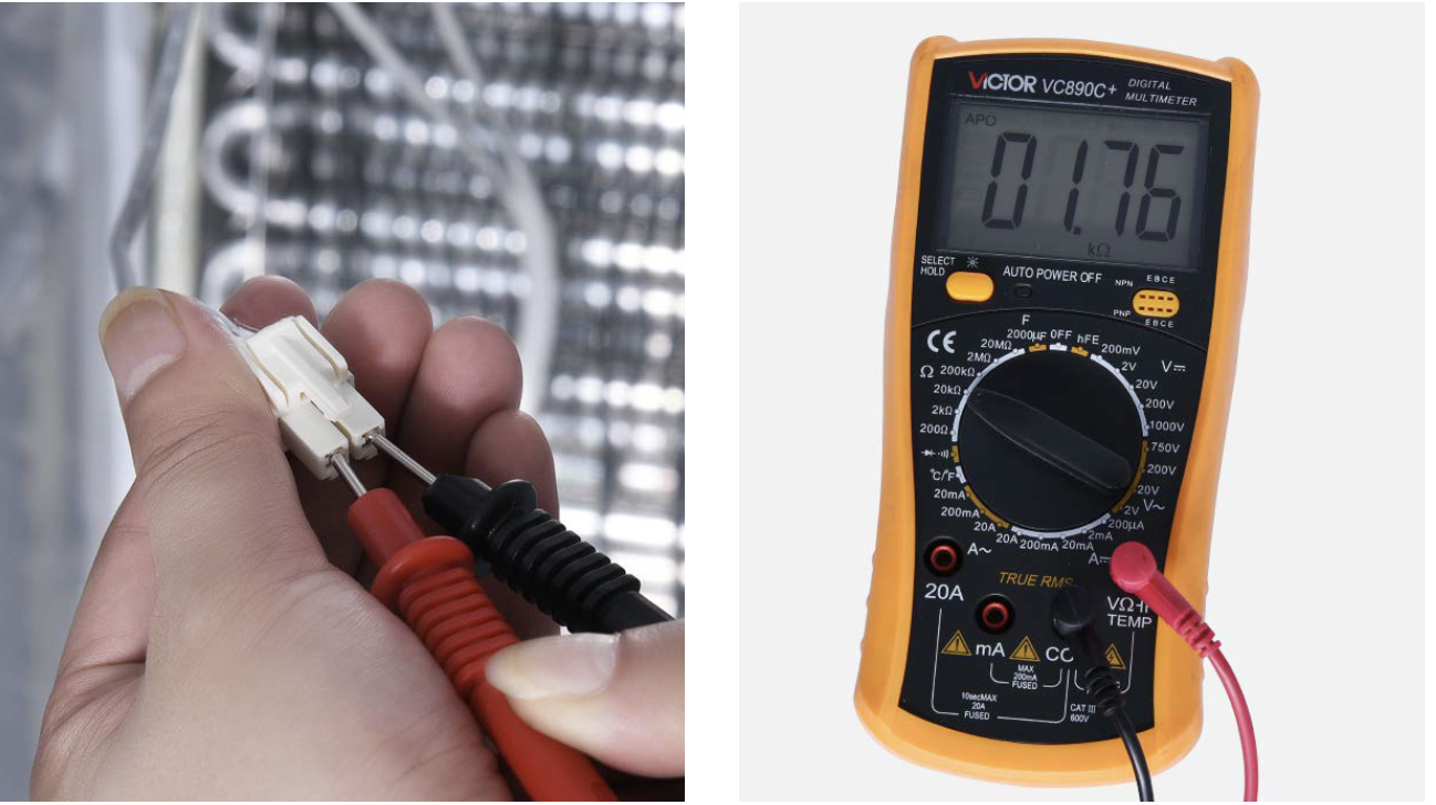
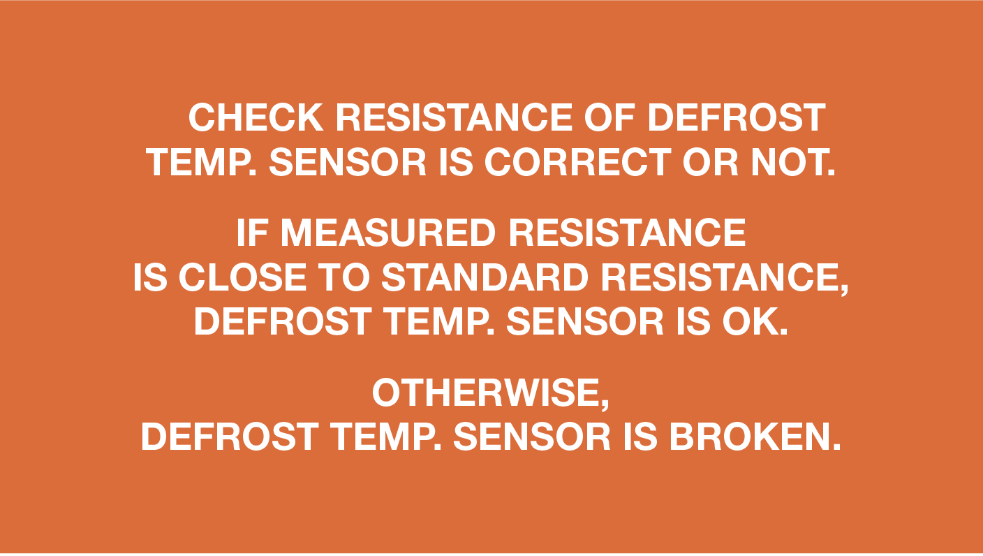
Set multimeter to resistance gear.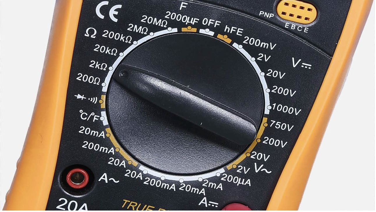
Step 4
Test resistance of sensorfrom terminal in PCB
area.

Step 5
Take note of value.
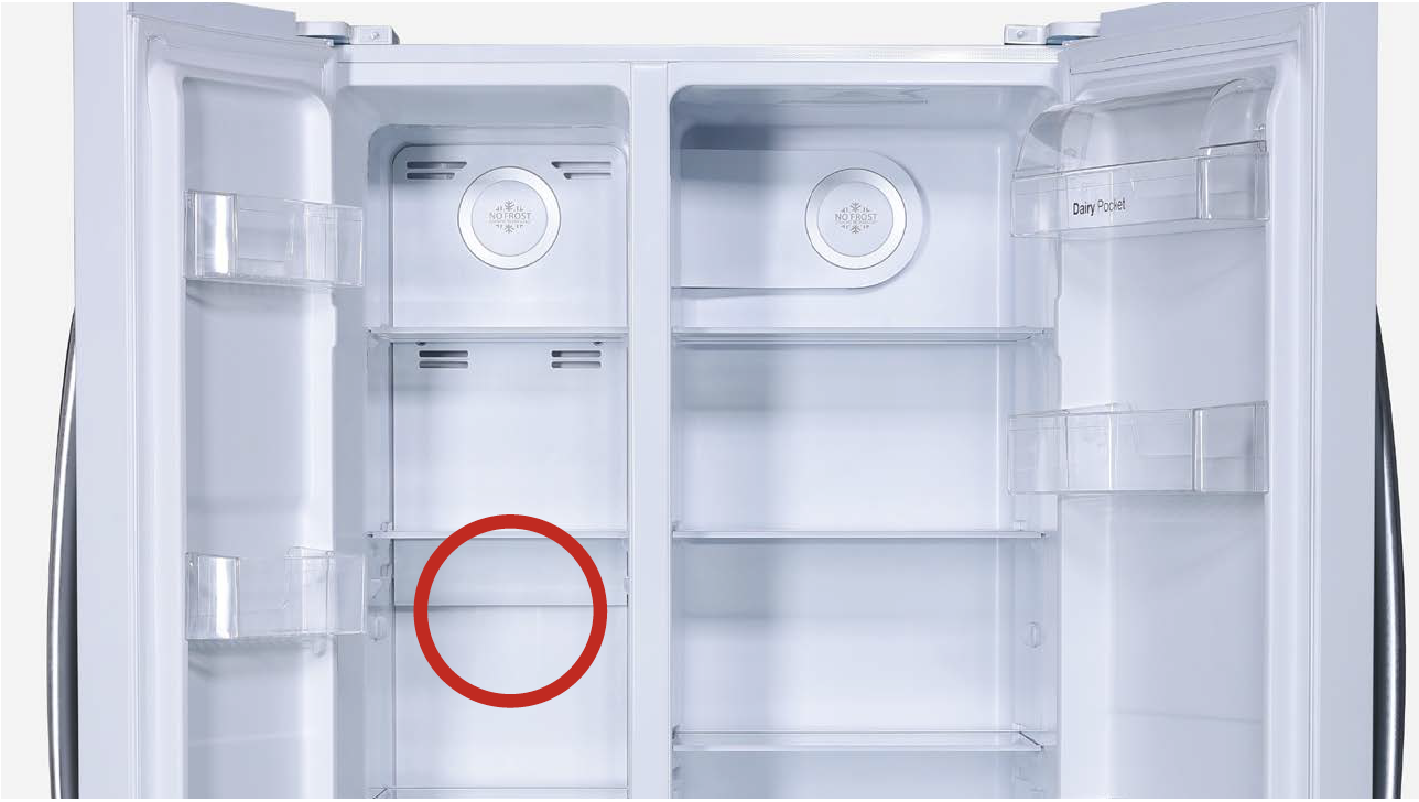
Step 6
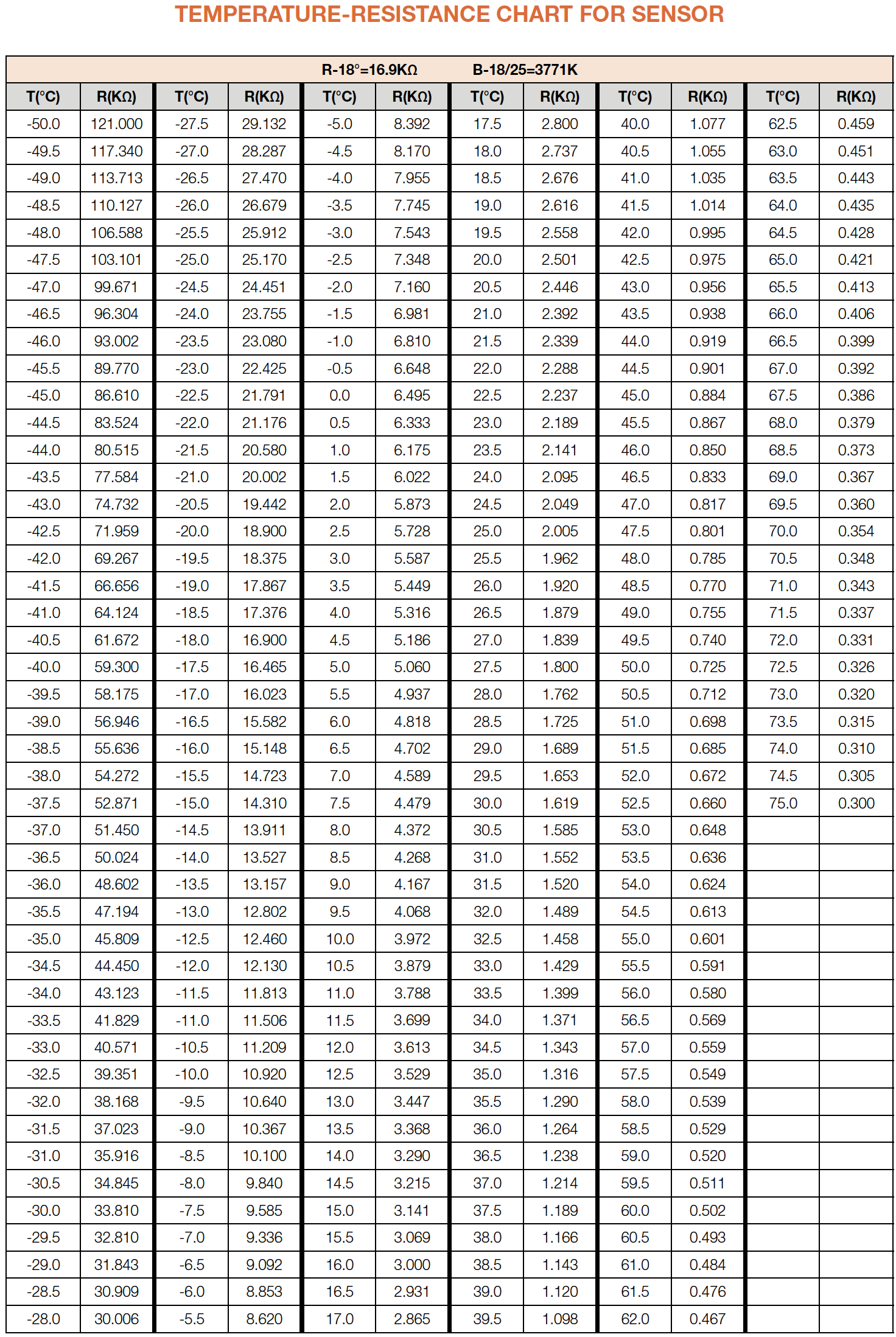
Measure the temperatureof freezer air duct, near the
defrost temp. sensor.
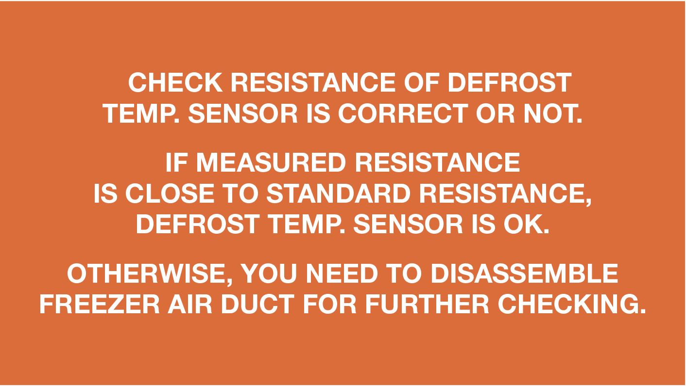
Use measured temperature
to find the standard
resistance value in
Temperature-Resistance
Chart of Sensor.
DIAGNOSIS 1

PROCEDURE 1

Step 1
Remove all freezerdrawers.

Step 2
Remove all freezer
shelves.

Step 3
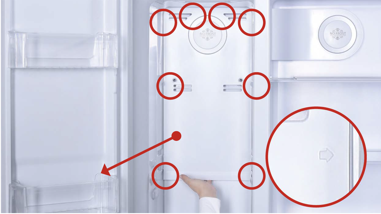
Remove screw covers (total of two) on upperfreezer air duct with Slotted Screw Driver.

Step 4
Unscrew screws (totalof two) on upper freezer
air duct with Cross-head
screw driver.

Step 5
Catch bottom of air ductupper freezer air duct
and pull all buckles (total
of 8) down.
Step 6
Take out upper freezerair duct by tilting to one
side.
Pay attention to the
connectors when pulling
out the air duct.
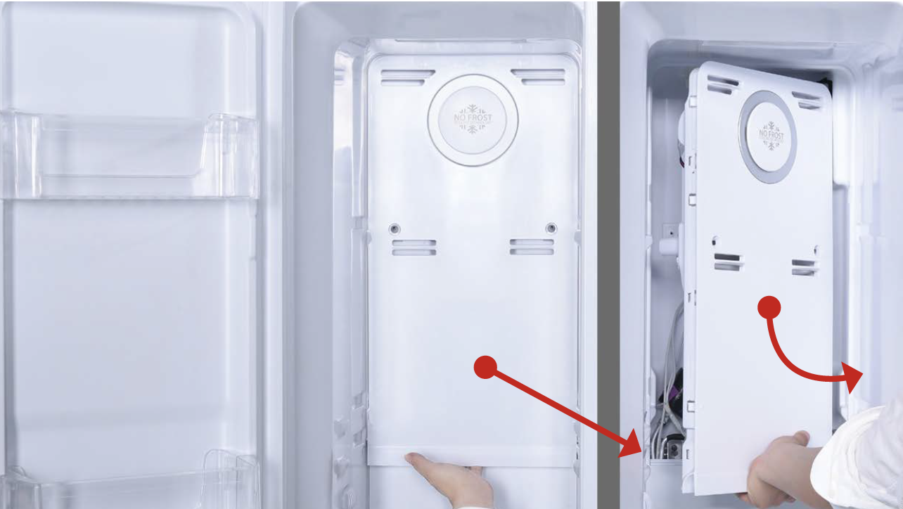
Step 7
Disconnect the terminalfor fan motor and move
upper freezer air duct
away.
Step 8
Remove the screw coveron bottom freezer air
duct with Slotted Screw
Driver.

Step 9
Unscrew the screw onbottom freezer air duct
with Cross-head screw
driver.
Step 10
Catch bottom of air ductbottom freezer air duct
and pull all buckles
(total of 10) down.

Step 11
Take out the lower airduct, tilting to one side.

CHECK AND TEST 2
Step 1
Check if sensor attachedin correct position, as
shown in picture.

Step 2
Check if sensor attachedin correct position, as
shown in picture.

Step 3
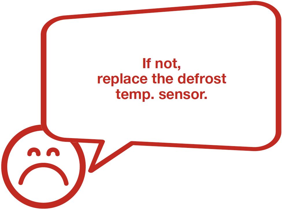
Check if wire of defrostsensor is broken.
If yes, replace it with a
new one.

Step 4
Disconnect terminal ofdefrost temp. sensor (B).

Step 5
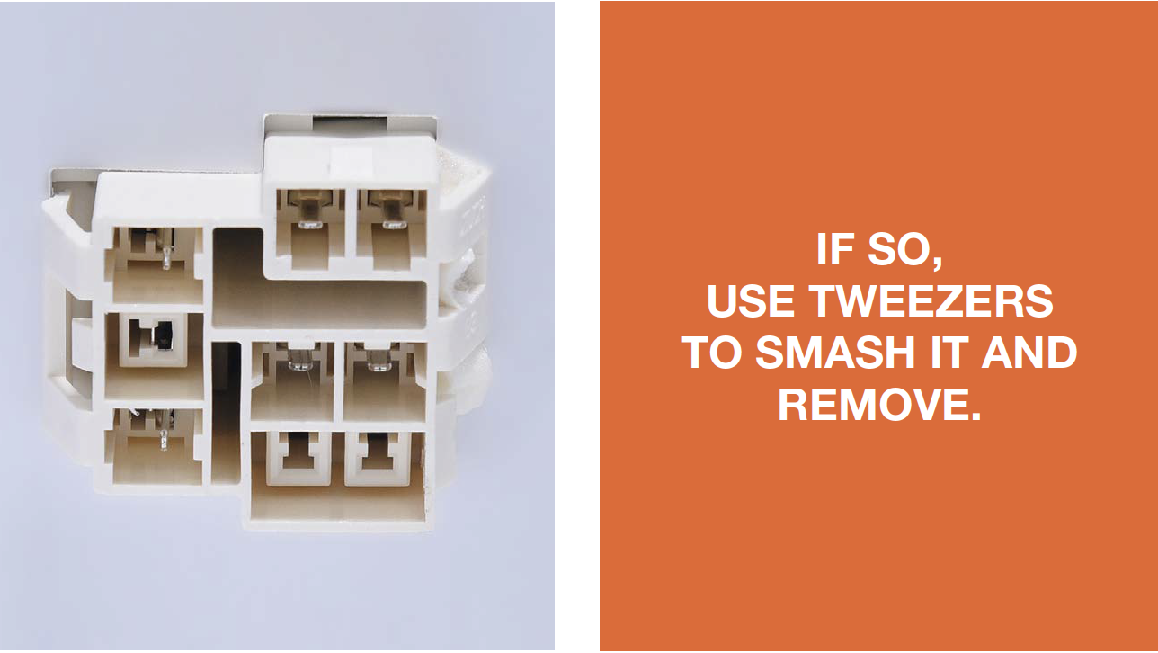
Check if the terminal isstuffed with foam.
Step 4
Measure resistance ofdefrost temp. sensor
from terminal in freezer,
and take note of it.
Step 7
Measure the temperatureof defrost temp. sensor.
Use measured
temperature to find the
standard resistance
value in Temperature-
Resistance Chart for
Sensor.


DIAGNOSIS 2


CHECK AND TEST 3

DIAGNOSIS 3


CASE 1:
METAL DOOR

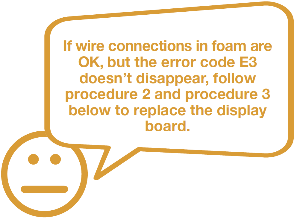
PROCEDURE 2

Step 1
Push a 6mm suckeronto display and turn
the knob to strengthen
suction force.

Step 2
Attach strap to knobto facilitate pulling out
display board.

PROCEDURE 3
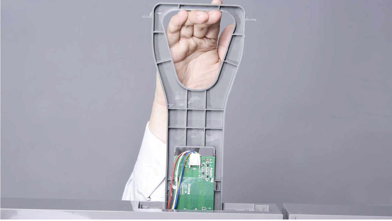
Tip 1
After connecting
terminal, please tape
wires in place to prevent
crushing by the cover.

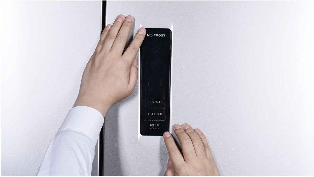
Tip 2
After inserting displayn into cavity, press edge
until you hear a clicking sound, this means the
board is pushed properly into final position.
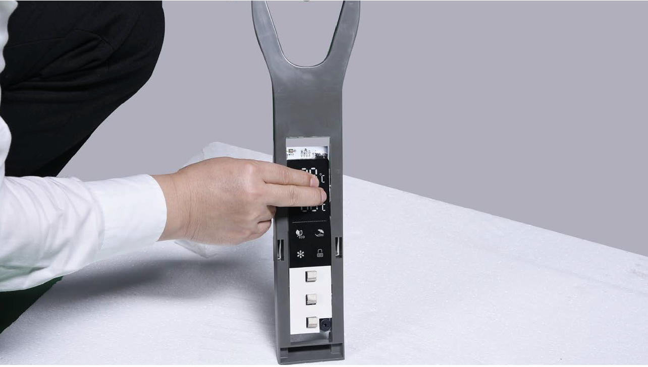
Please press all buttons on display
board to make sure display functions
properly.
CASE 2:
GLASS DOOR

PROCEDURE 2

Step 1
Lever off the cover ondoor cap.

Step 2
Remove the screws (intotal 2).

Step 3
Pull out the plastic;
Step 4
Disconnect the terminalfor display panel.
Step 5
Remove tape.
Step 6
testo testoPush display out by thecorner.

PROCEDURE 3
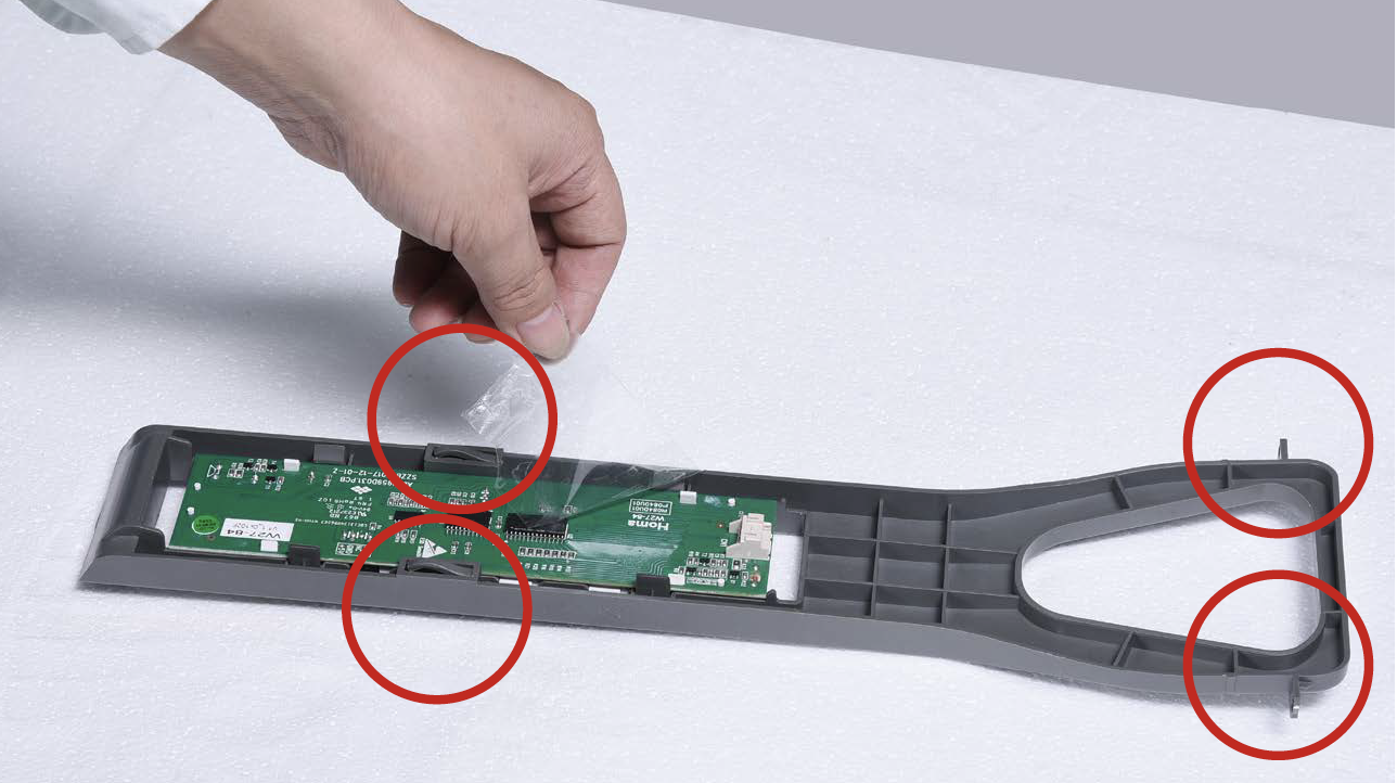
Tip 1
Please press all buttonson display board to verify
if it is working properly.
Make sure all words and
icons are clear.

Tip 2
If not clear, disassembleand put tape on points
indicated by red circles.
CHECK AND TEST 4

PROCEDURE 4

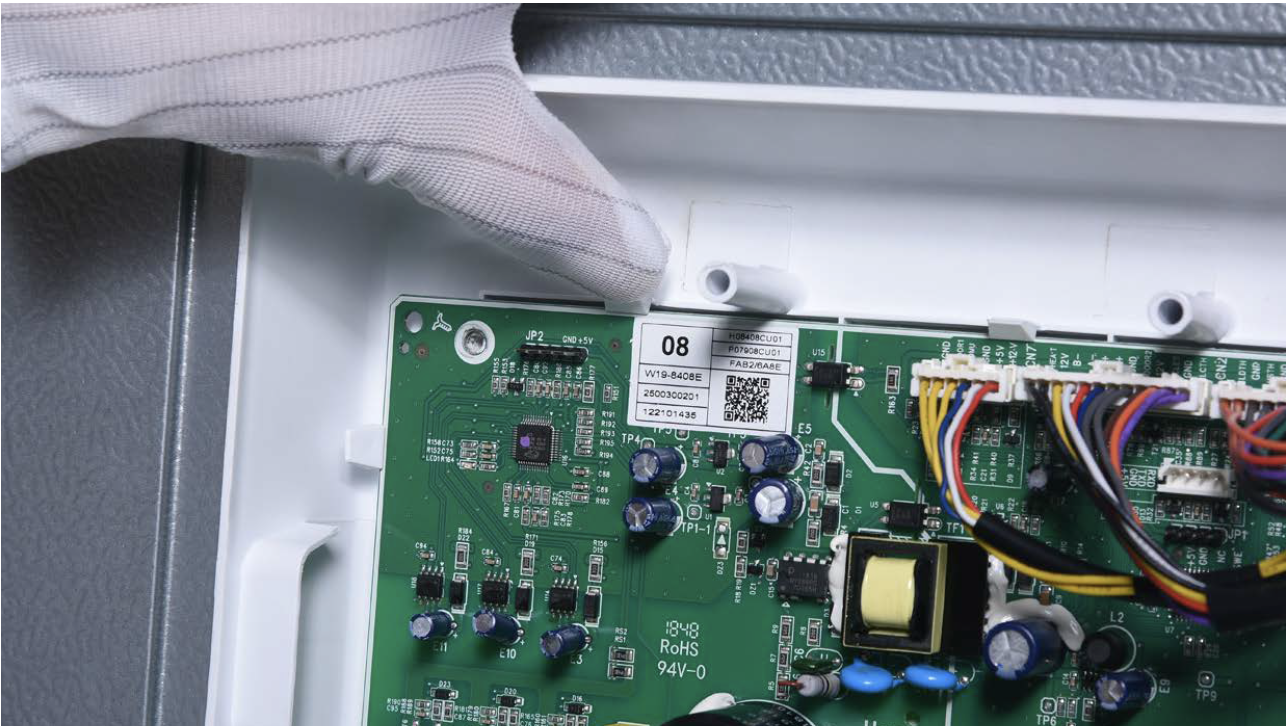
Step 1
Unscrew cover ofmainboard with a
Cross-head screwdriver.

Step 2
Disconnect terminals.
Step 3
Prize off earthing wires.
Step 4
Unscrew the mainboard.
Step 5
Prize off the buckle toremove mainboard.

PROCEDURE 5

CHECK AND TEST 5

PROCEDURE 5
Tip 1
When restoring the upper freezer air duct,fasten the wires to avoid crushing them with air
duct.

Tip 2
All buckles should be pushed into proper finalposition. If not, please repeat installation.


GO BACK TO COMPONENT LIST