

CHECK AND TEST 1
Step 1
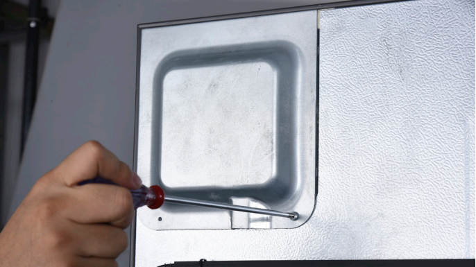
Unscrew cover of mainboard with a Cross-head screwdriver.
Step 2
Check if terminal in PCB area is inserted to final position. If not, reinsert it to final position.
Step 3
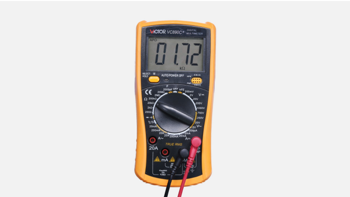
Set multimeter to resistance gear.
Step 4
In PCB area, measure the resistance of defrost temp. sensor with a multimeter.
Step 5
Take note of value. .
Step 6
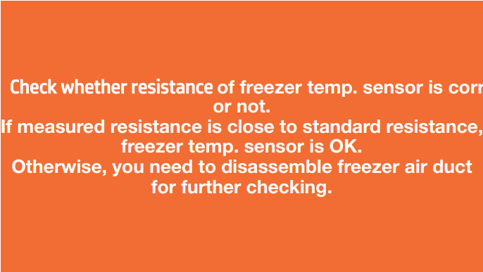
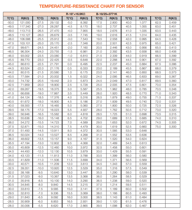
Measure temperature of freezer temp. sensor. Use the measured temperature to find the standard resistance value in Temperature-Resistance Chart for Sensor.


DIAGNOSIS 1


PROCEDURE 1
Step 1
Remove all shelves.

Step 2
Remove upper drawer.
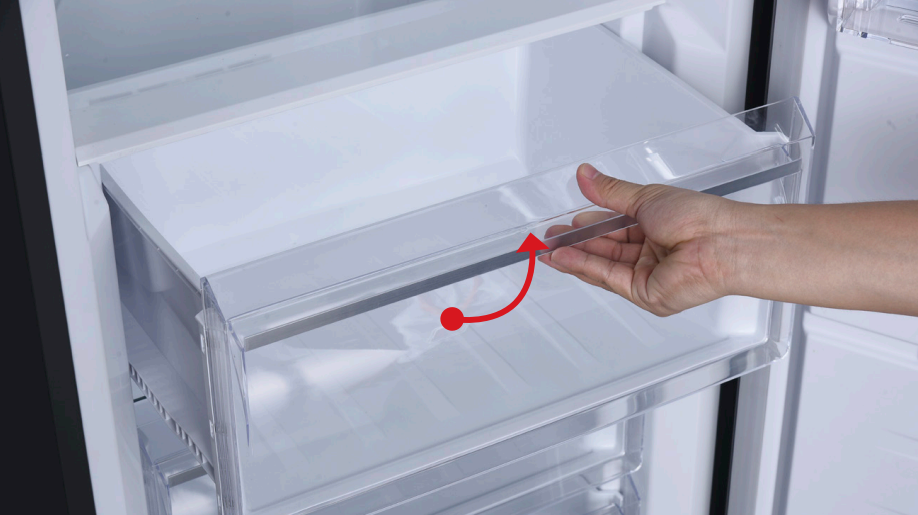
Step 3
Remove bottom drawer.

Step 4
Remove drawer cover.

Step 5
Remove glass shelves under drawers.
Step 6
Prize off the decorative panel and take if off.
Step 7
Unscrew the upper air duct.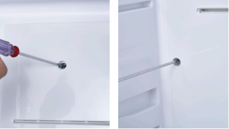
Step 8
Disconnect the terminals. Pull outward and take off the upper air duct.

Step 9
Unscrew the lower airduct.

Step 10
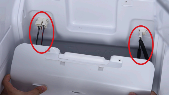
Disconnect the connectors between airduct and cabinet.Step 11
Remove the lower air duct.


CHECK AND TEST 2
Step 1
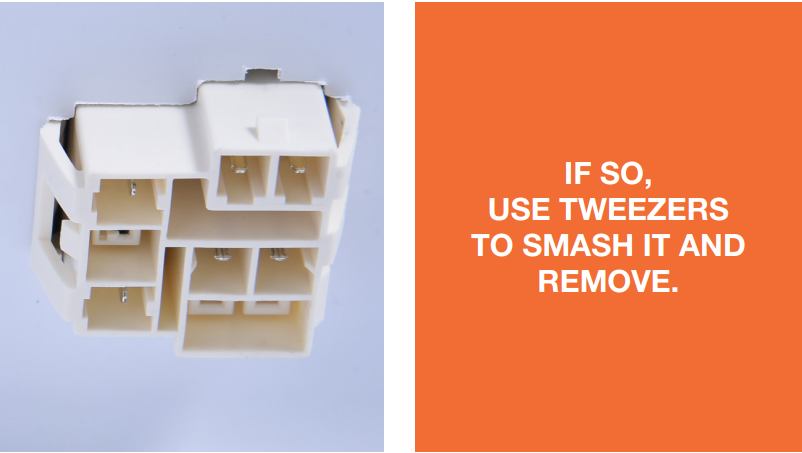
Check if the terminal is
stuffed with foam.
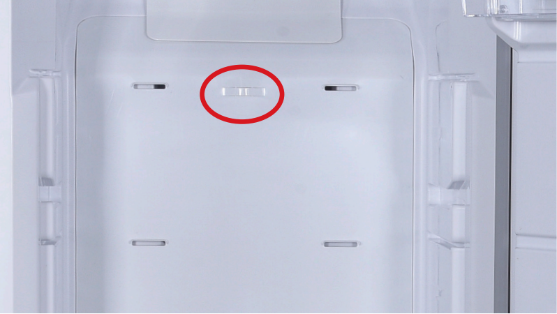
Step 3
Measure resistance of freezer temp. sensor from terminal in freezer air duct cover.
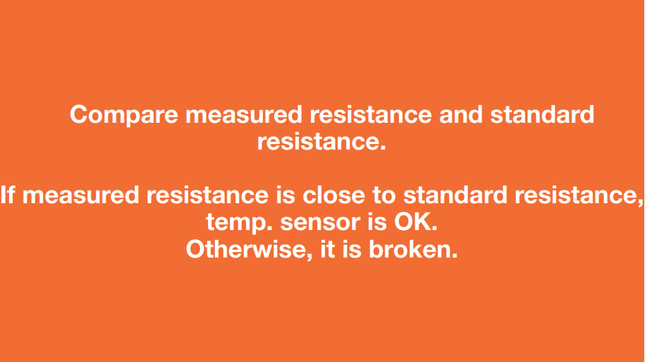
Step 5
Measure temperature of freezer temp. sensor. Use the measured temperature to find the standard resistance value in TemperatureResistance Chart for Sensor.

DIAGNOSIS 2


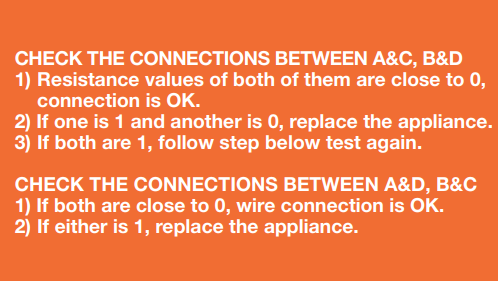
CHECK AND TEST 3
Step 1
Set multimeter to resistance gear.
Step 2
Put detector into one end of wires in PCB area. Put another detector into end of wires behind air duct.

DIAGNOSIS 3


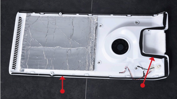
PROCEDURE 2
Tip 1
Make sure the sealing sponges are in good condition.
Tip 2
When reinstalling the air duct, fasten the wires to avoid crushing with air duct.
Tip 3
Check to see if there is a wide gap between air duct and cabinet. If there is, reinstall air duct.
 CHECK AND TEST 4


DIAGNOSIS 5


GO BACK TO COMPONENT LIST