8.2 RELIABILITY FAULTS:
WRONG OR NO ICONS
ON DISPLAY


CHECK AND TEST 1
Step 1
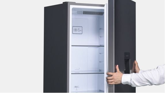
If you verify that the wrong icons or no icons are shown on display or icons are flashing... 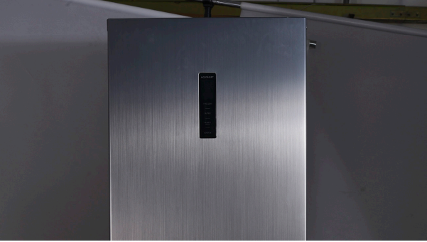

DIAGNOSIS 1

CHECK AND TEST 2
Step 1
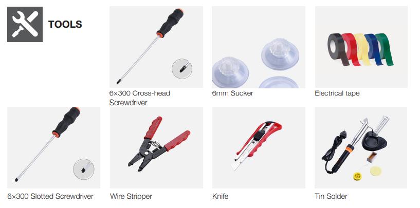
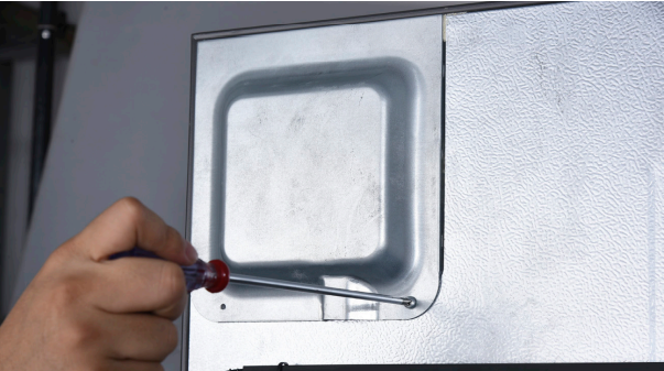
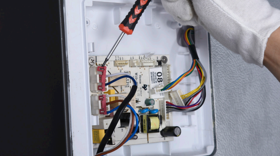
Unscrew cover of
mainboard with a
cross-head screwdriver.
Step 2
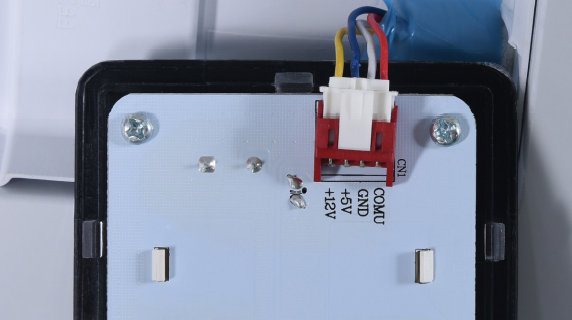
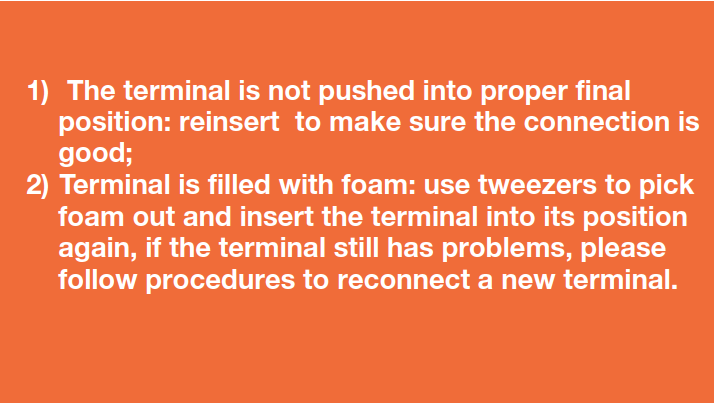
Check if terminal in PCB area is inserted to final position. If not, reinsert it to final position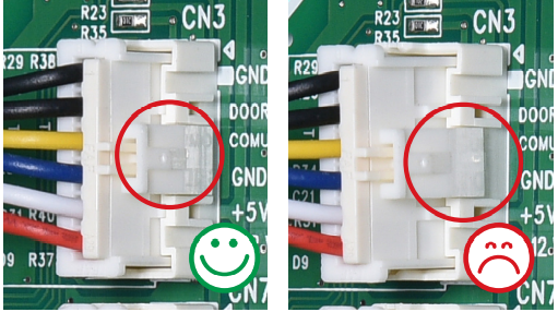
Step 3
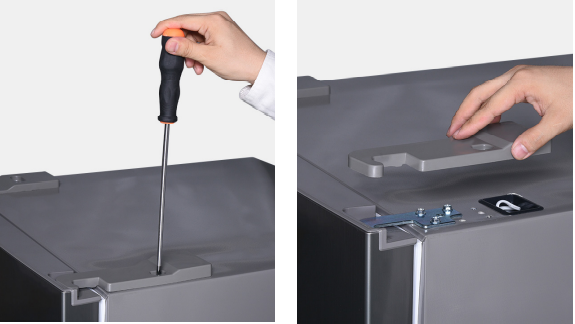
Unscrew hinge cover.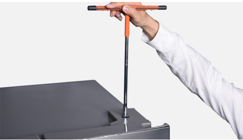
Step 4
Check if terminal in hinge cover is inserted to final position. If not, reinsert it to final position.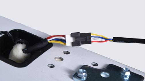
DIAGNOSIS 2

CHECK AND TEST 3
Step 1
Check if wires in PCB area and hinge cover area are damaged or not.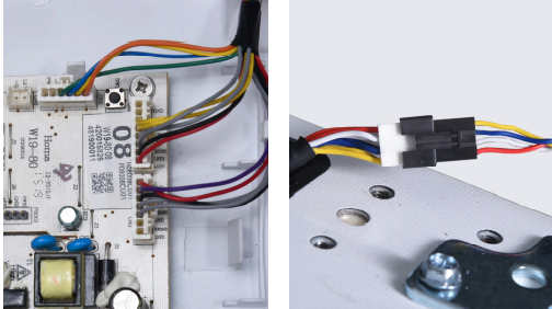

DIAGNOSIS 3

PROCEDURE 1
Step 1
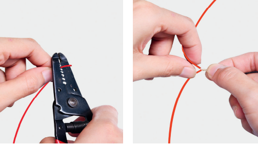
Cut wire off.
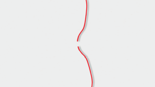
Step 2
Peel off the sleeves. Step 3
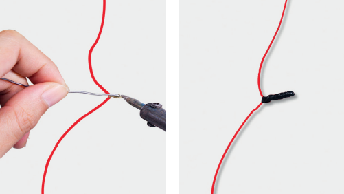
Check to ensure proper wire order and connect them
Step 4
After connecting terminal, please use tape
to fasten wires to avoid crushing with cover.
Step 5
After putting display into cavity, press edgeuntil you hear a clicking sound, this means the
board is pushed into final position.

PROCEDURE 2
Step 1
Push a 6mm sucker
onto display and turn
the knob to strengthen
suction force 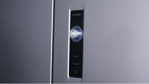
Step 2
Wrap a belt around knob to make it easier to pull out of display board. 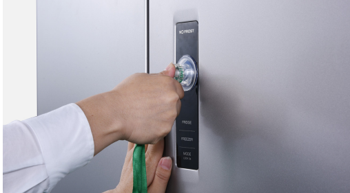
Tips for installing display.
Tip 1
After connecting terminal, please use tape to fasten wires to avoid crushing with cover.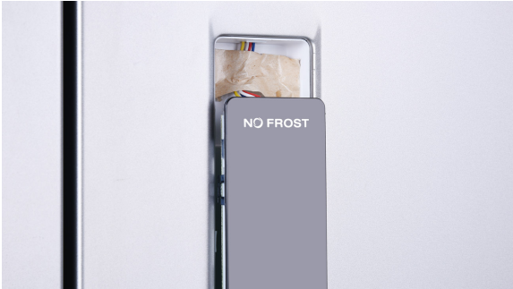
Tip 2
After putting display into cavity, press edge until you hear a clicking sound, this means the board is pushed into final position. 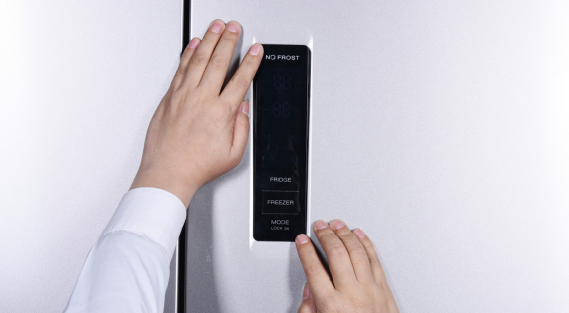
Tip 3
Please press all buttons
on display board to make
sure it works well. 
CHECK AND TEST 4
Step 1
Check if connection and wire order in display area are correct or not.

DIAGNOSIS 4


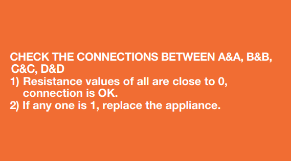
CHECK AND TEST 5
Step 1
Set multimeter to resistance gear 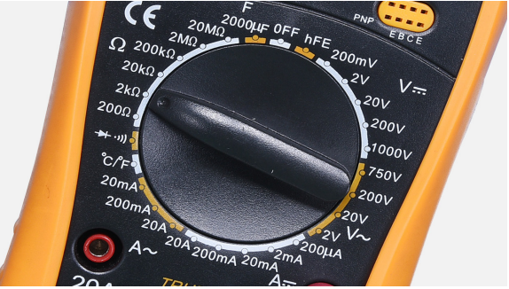
Step 2
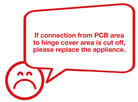
Check wire connection from PCB area to hinge cover area.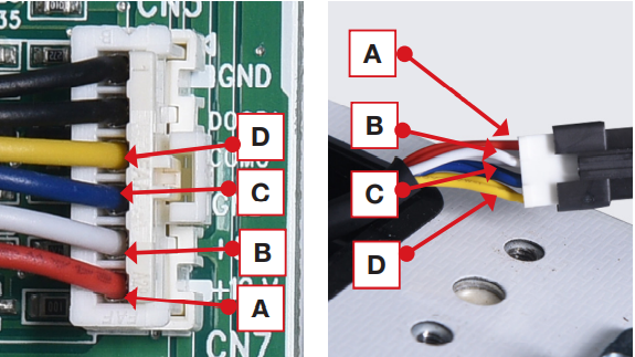
Step 3
Check wire connection from hinge cover area to display area. 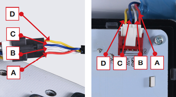

DIAGNOSIS 5
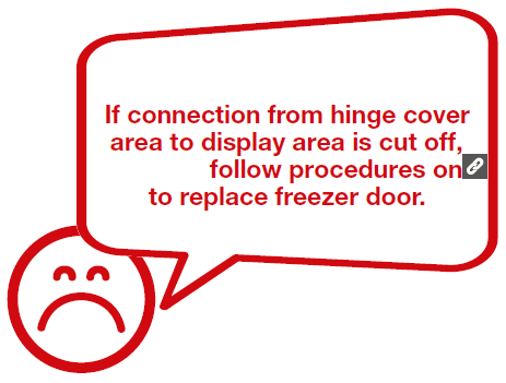

PROCEDURE 5
Step 1
Unscrew hinge cover Step 2
Remove the cover.
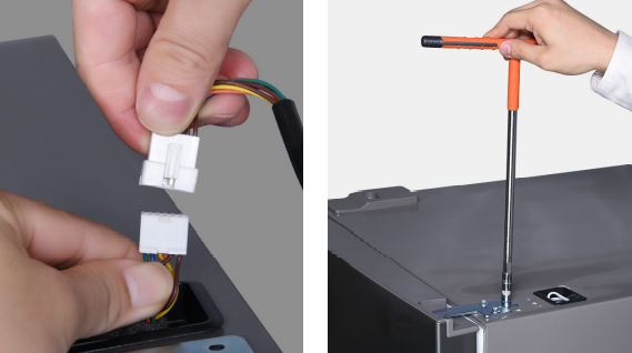
Step 3
Disconnect the terminals. Step 4
Unscrew 3 bolts and remove the top hinge.
Step 5
Remove the door 
Tip 1
Make sure gasket is attached well.

CHECK AND TEST 6


PROCEDURE 6
Step 1
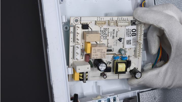
Unscrew cover of mainboard with a Cross-head screwdriver.
Step 2
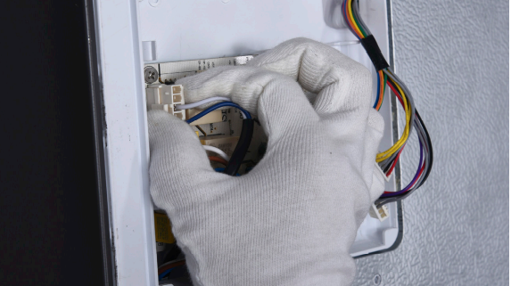
Prize off the connector buckles.
Step 3
Disconnect the connectors.
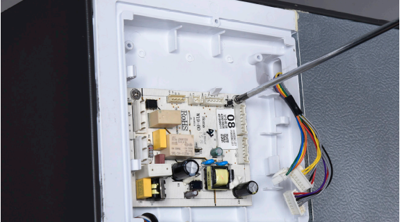
Step 4
Unscrew the mainboard.
Step 5
Prize off the buckle to remove mainboard.
Reverse steps above to install a new mainboard.


GO BACK TO FAULT LIST RELIABILITY