


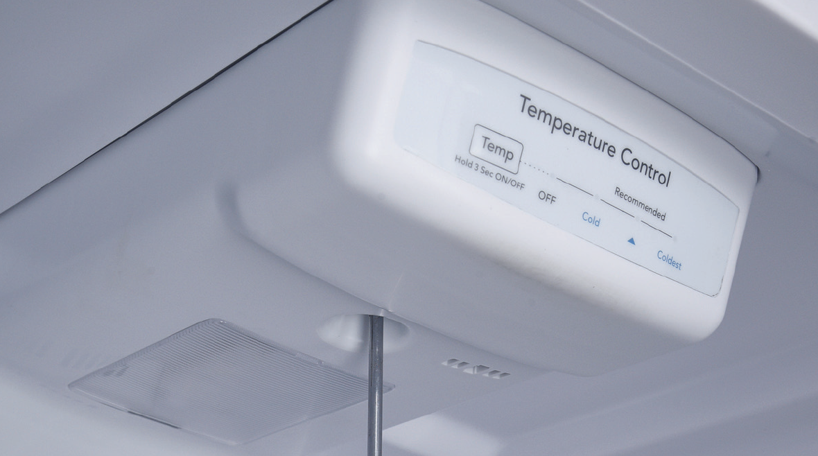
Step 2
Remove the LED lamp cover and the screw.
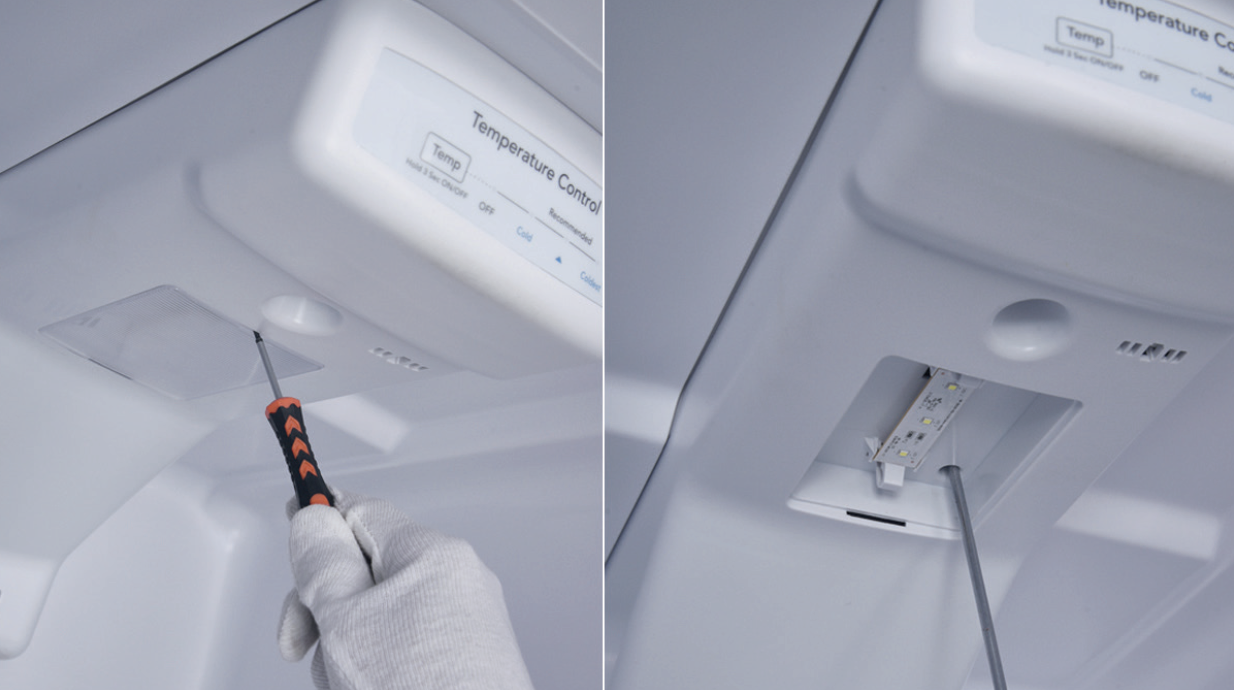
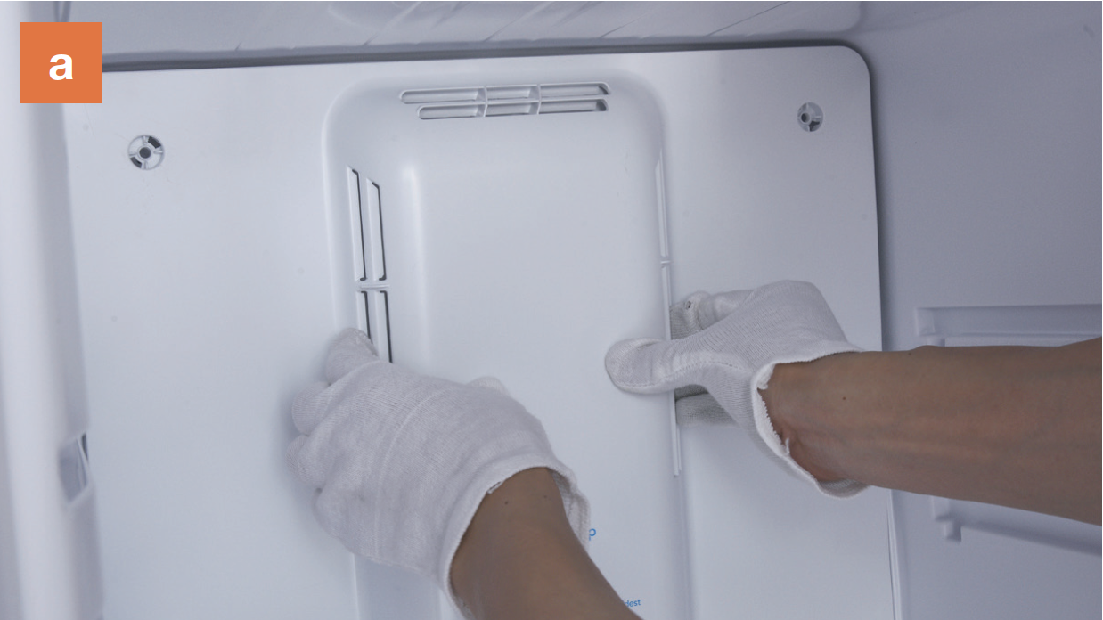
Step 3
Remove the air duct. 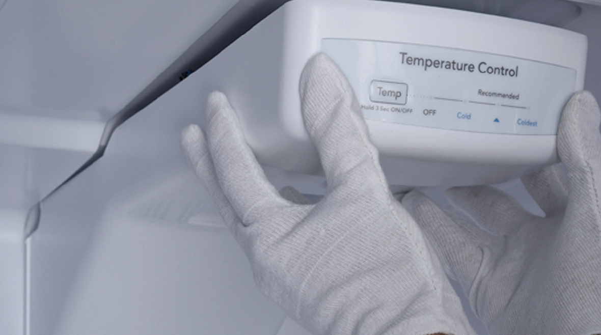
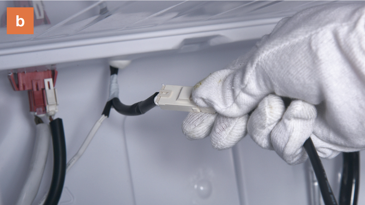
Step 4
Unplug the electrical wires.
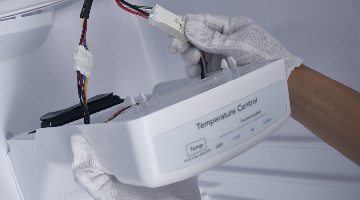
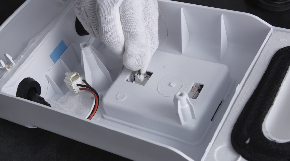
Step 5
Disconnect the terminal of potentiometer.
Step 6
Remove the UI film.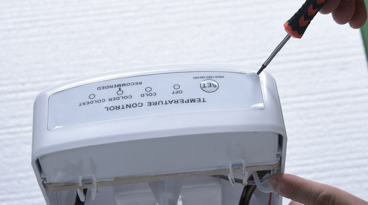
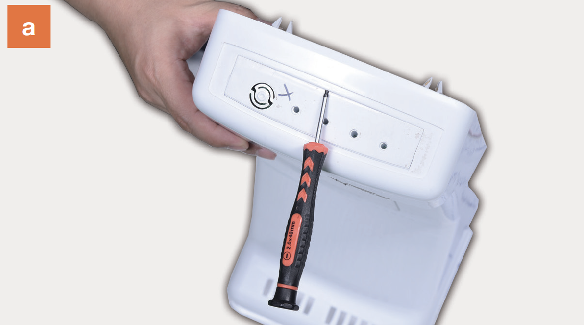
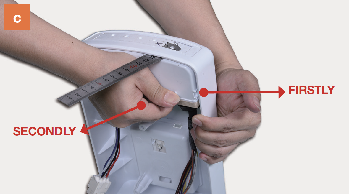
Step 7
Remove PCB box from air duct.a) Use 2 mm slot screw driver to create a gap in front side.
b) Insert a steel ruler to even the gap.
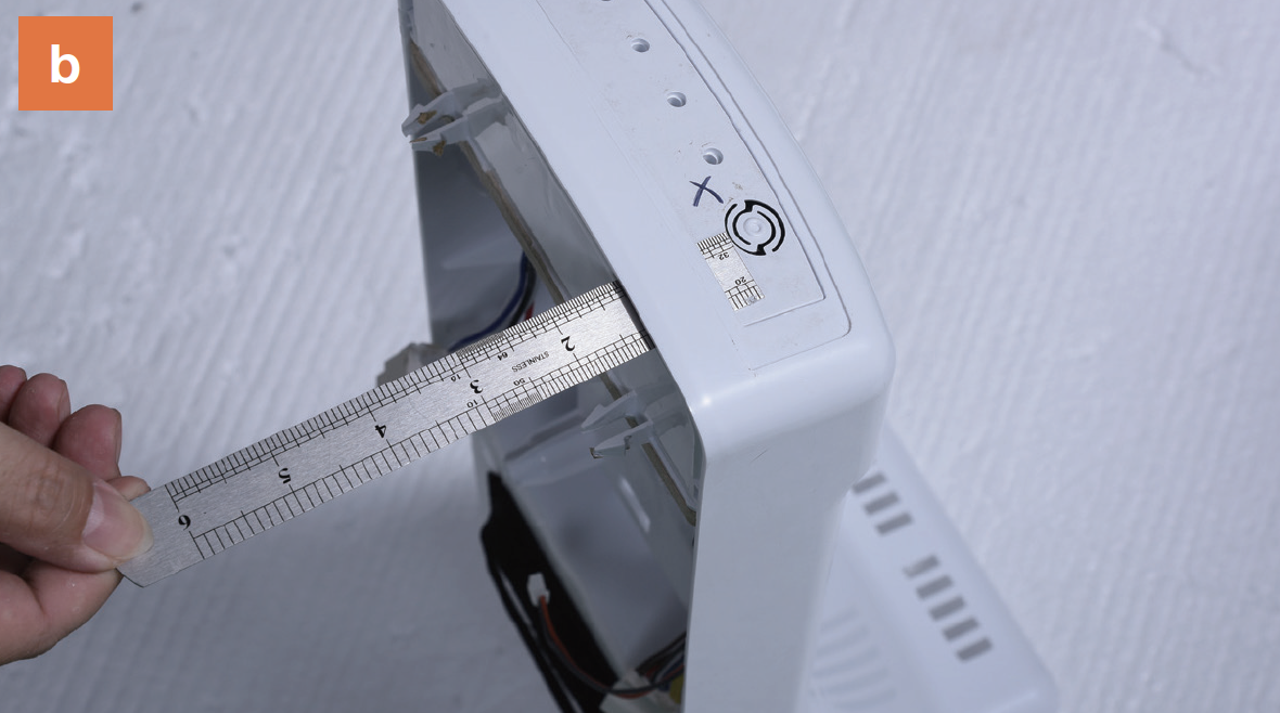
c) Pull the PCB box out.
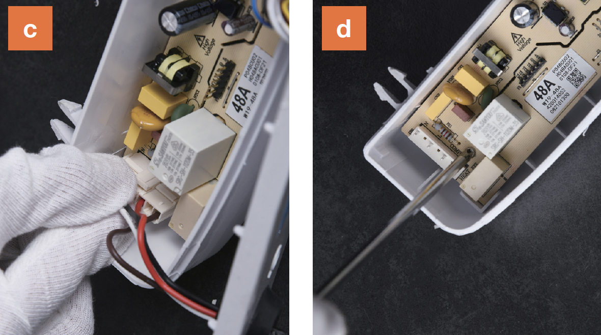
Step 8
Disassemble PCB box.a)Prize off the buckle;
b) Remove the cover;

c) Disconnect the terminals;
d) Unscrew and remove the PCB;

CHECK AND TEST 1
Step 1
Check if terminal is filled with foam.
Step 2
Remove foam with tweezers.
Step 3
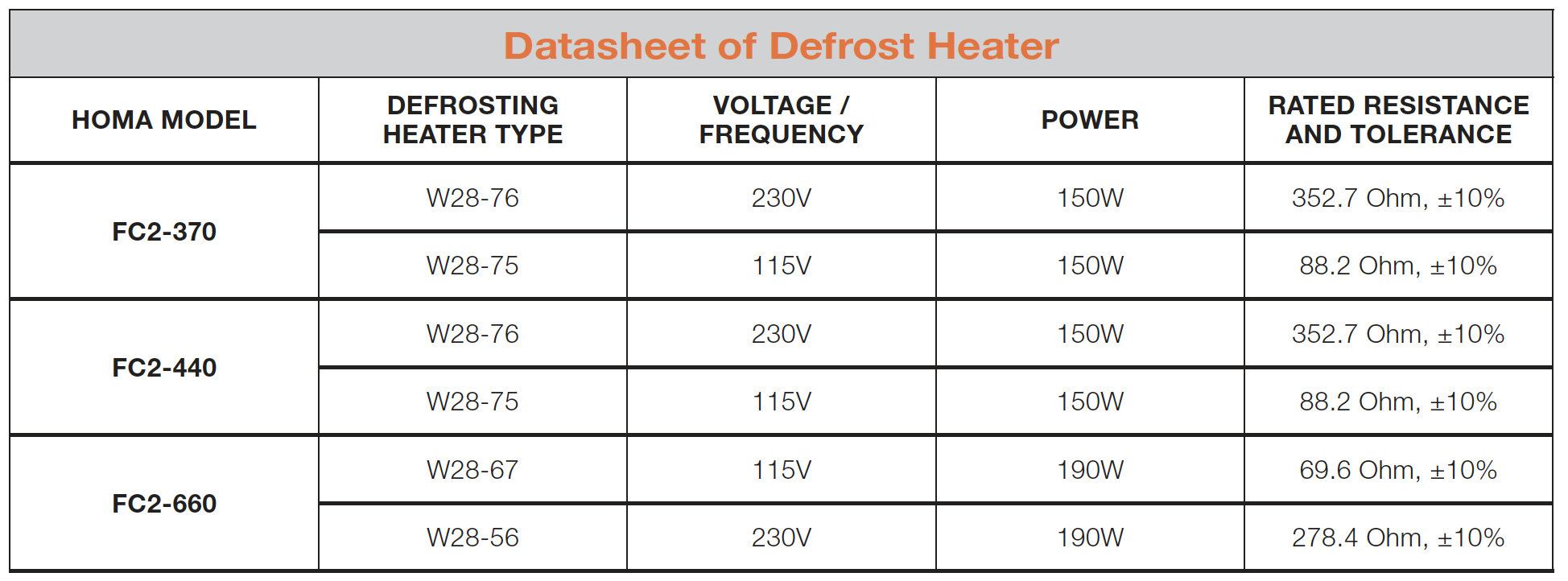
Reconnect wires and measure resistance ofheater from terminal in PCB area.

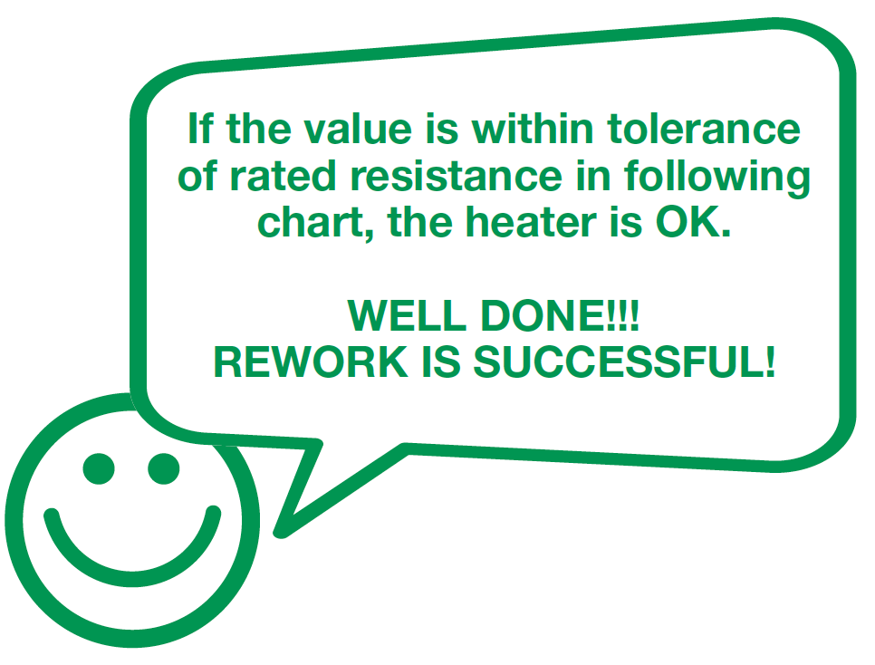
Step 4
Check the result.
DIAGNOSIS 1


PROCEDURE 2

Step 1
Remove freezer shelf.
Step 2
Lever 2 screw covers off.Step 3
Unscrew 2 screws.

Step 4
Remove air duct:a. Hold the air duct from air exit and pull air duct out;
b. Disconnect the terminal of fan motor;
c. Take air duct away.

CHECK AND TEST 2
Step 1
Check if terminal is pushed into final position.If not, please re-insert the terminal into the buckle.

Step 2
Check if the terminal is filled with foam.
Step 3
Remove foam with tweezers.
Step 4
Measure the resistance of heater from terminal
in freezer.

DIAGNOSIS 2

PROCEDURE 3

Step 1
Disconnect the terminal of heater.
Step 2
Take out heatconducting rod with slotted screw driver.
Step 3
Use 6mm cross-head driver to unscrew on leftand right.

Step 4
Lift evaporator and heater 20mm, thebottom must be higher than the edge of the
trough.

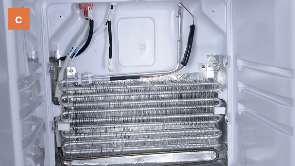
WARNING:
Be careful not to deform pipes in red square
during steps 4 & 5.
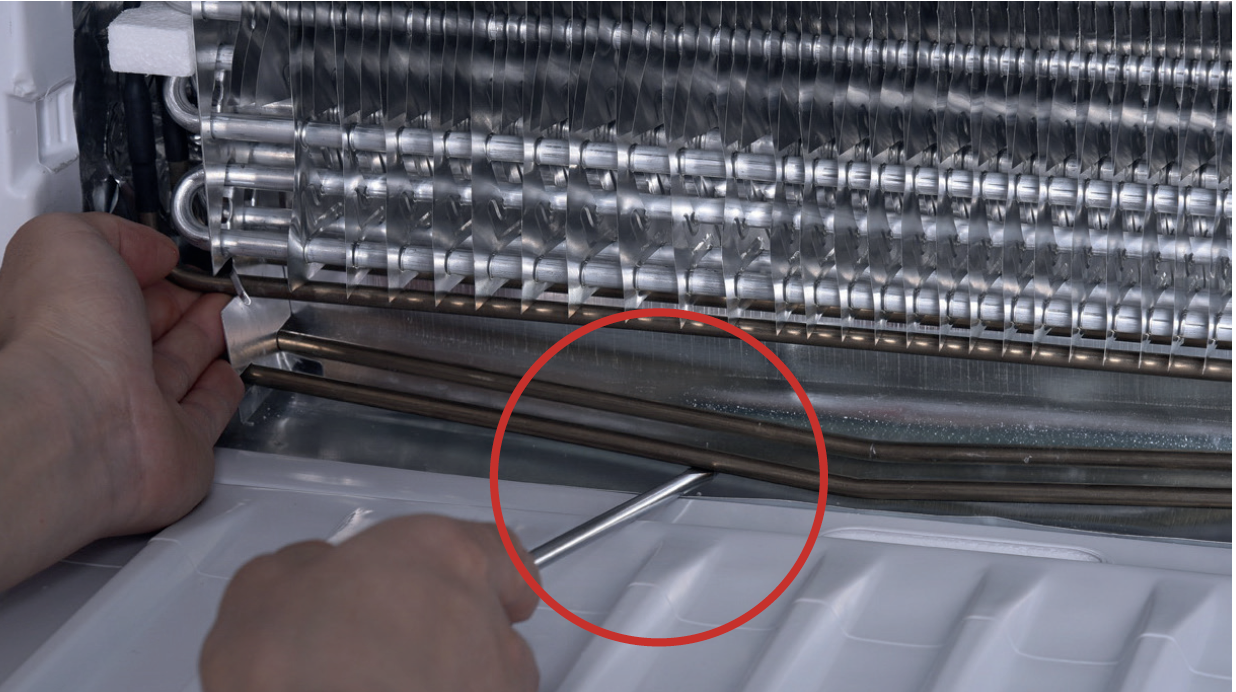

Step 5
Loosen the clips for fastening heater. Thereare 8 clips in total.

Step 6
Remove the heater.
PROCEDURE 4
CHECK AND TEST 3
Step 1
Reconnect the main control board to the cable.
Step 2
Reconnect the electrical wires.
Step 3
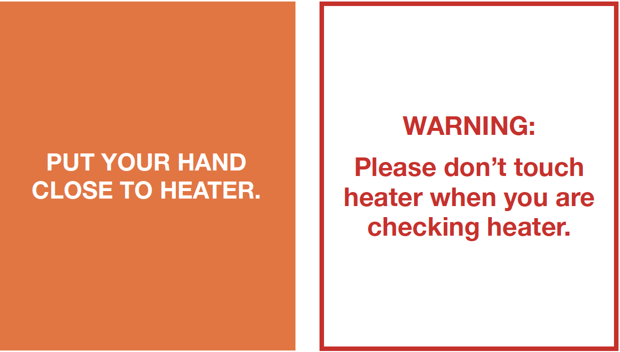
Heat fridge temp. sensor.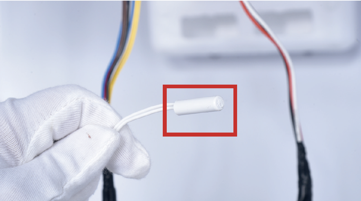
Step 4
Press LED switch and hold on, then press thebutton on mainboard for 3 seconds to start
manual defrost.

DIAGNOSIS 3

CHECK AND TEST 4
Step 1
Connect 2 ends on terminal in PCB area.
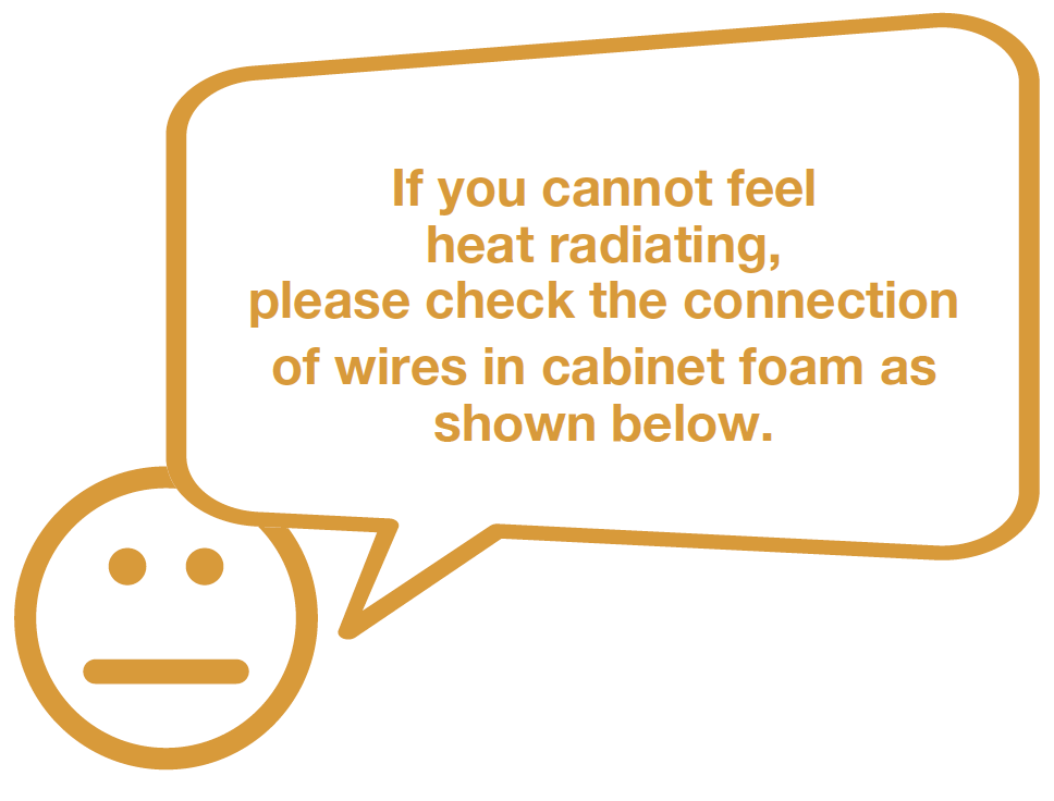
Step 2
Check the connection of wires in foam.
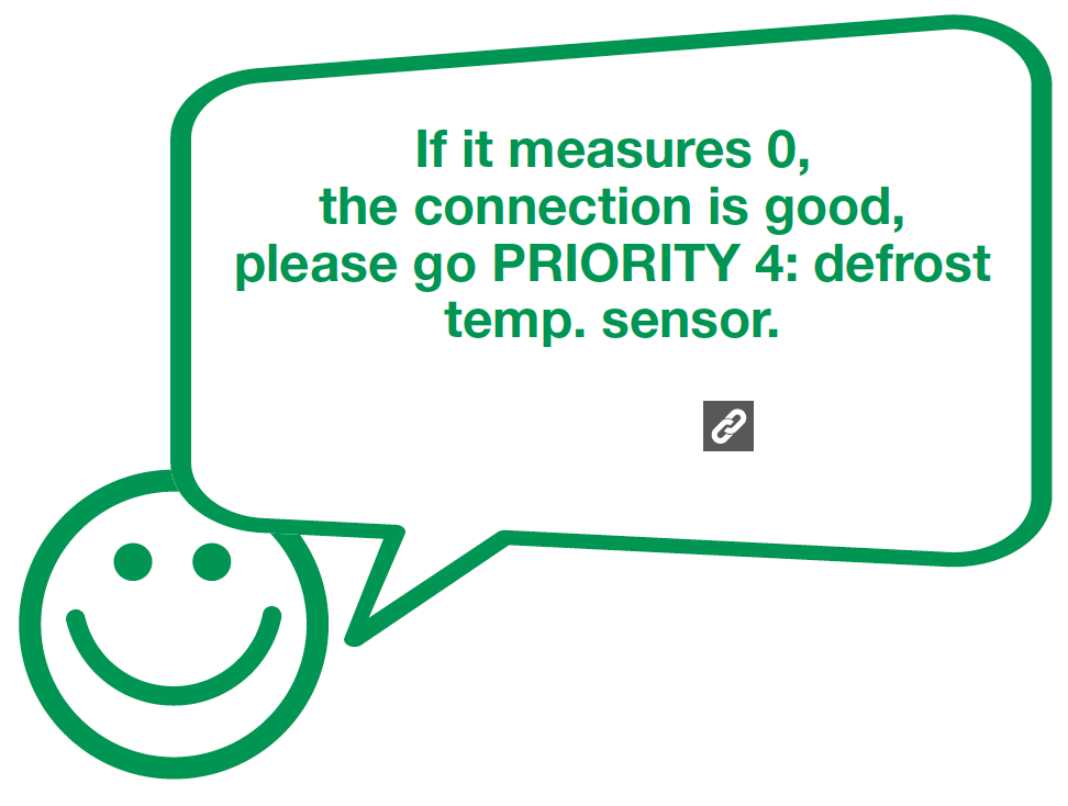
DIAGNOSIS 4

PROCEDURE 5
Tip 1
Firstly insert the air duct into the slot at thebottom.

Tip 2
When reinstalling air duct, move wires outof the way to prevent crushing with air duct

Tip 3
After pushing air duct back into position, youshould hear a clicking sound. If there is no
click, please repeat again.

PROCEDURE 3

GO BACK TO COMPONENT LIST