

CHECK AND TEST 1
Note
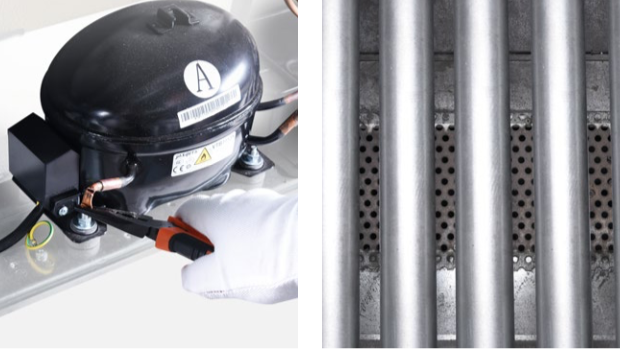
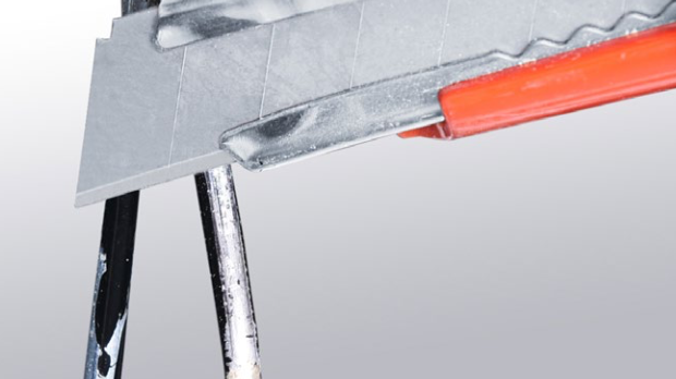
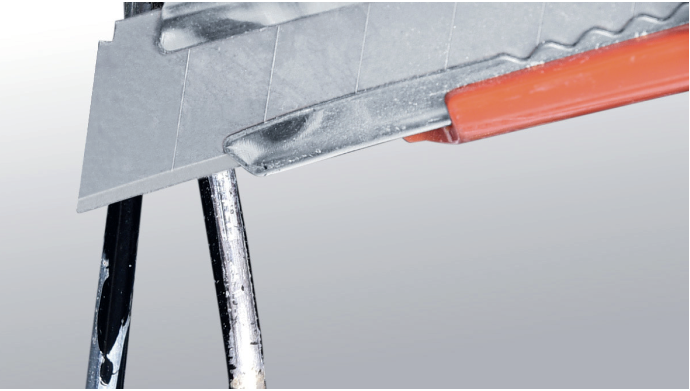
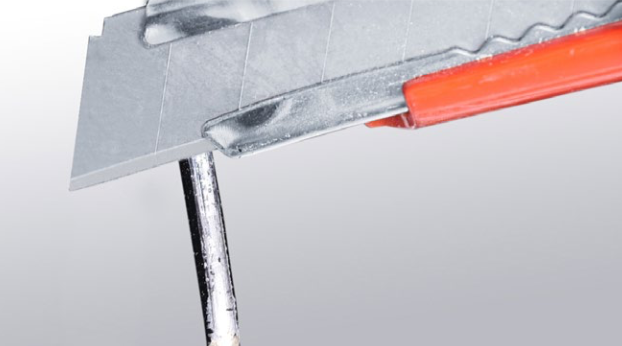
Step 1
Discharge refrigerant: use pliers to cut off charging tube.
Step 2
Discharge all refrigerant
toward the exhaust vent.
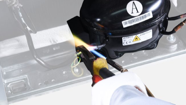
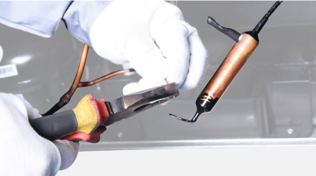
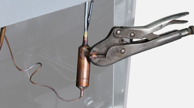
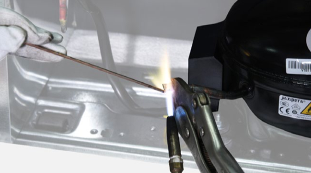
Step 3
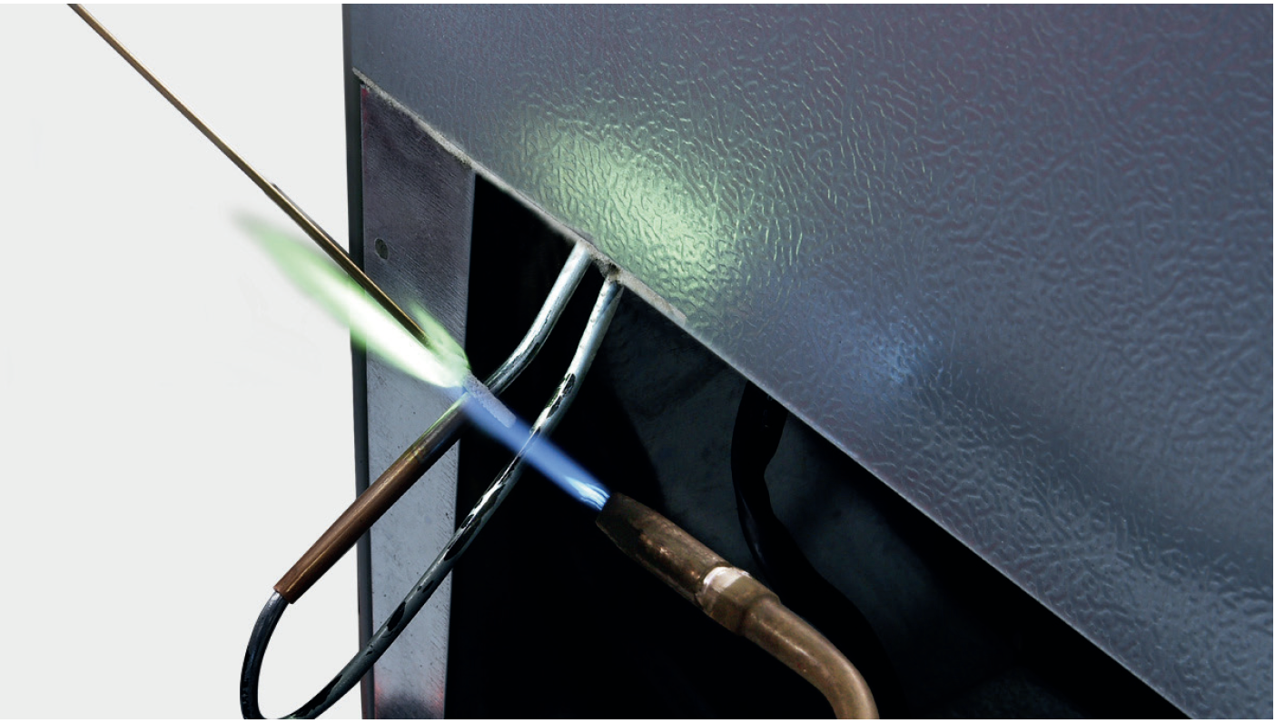
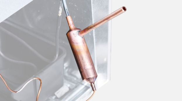
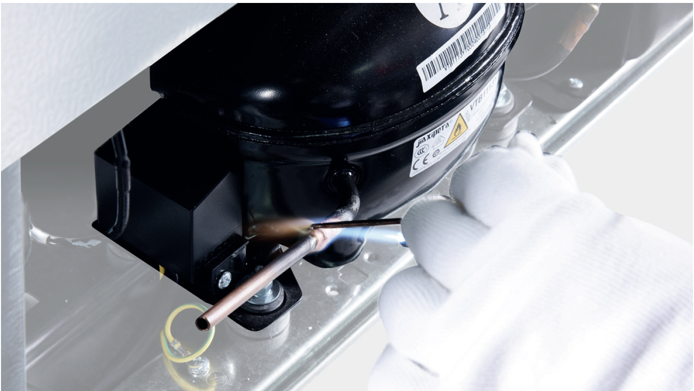
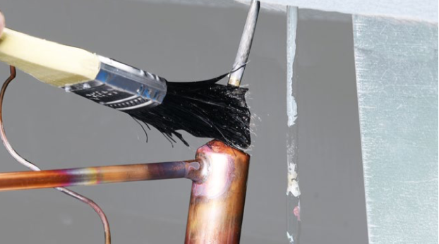
Melt brazing material with flame and use a pair of pliers to pull charging tube out.
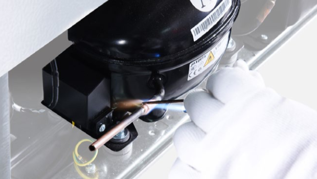
Step 4
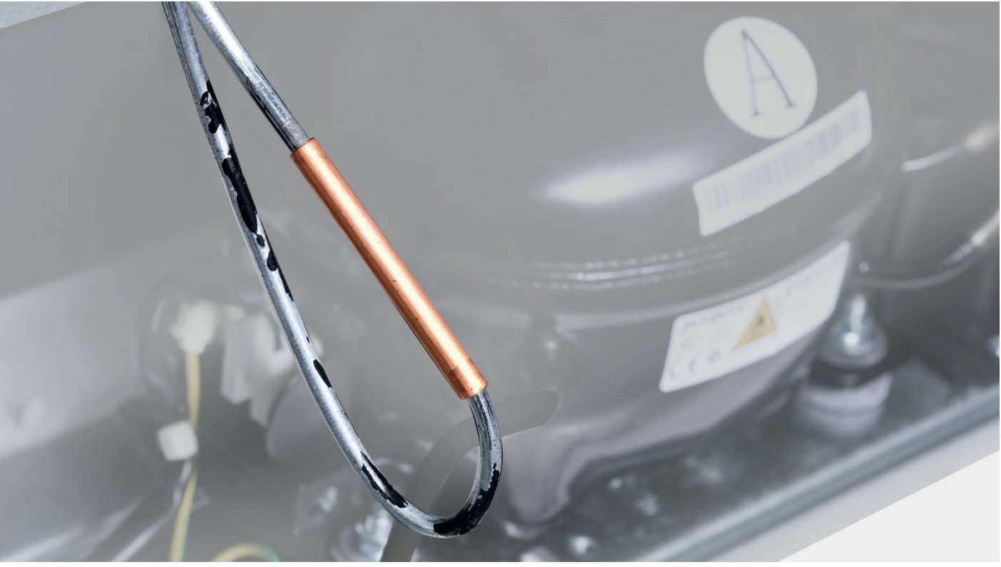
Re-braze a copper tube onto processing tube of compressor.
Get more details on
brazing requirements, on Annex B1
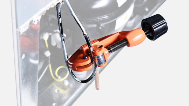
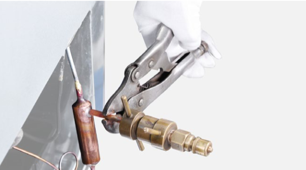
Step 5
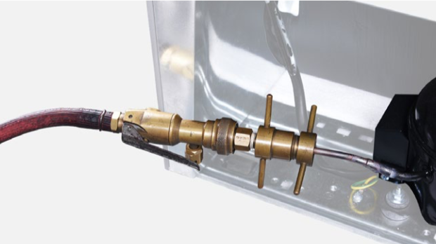
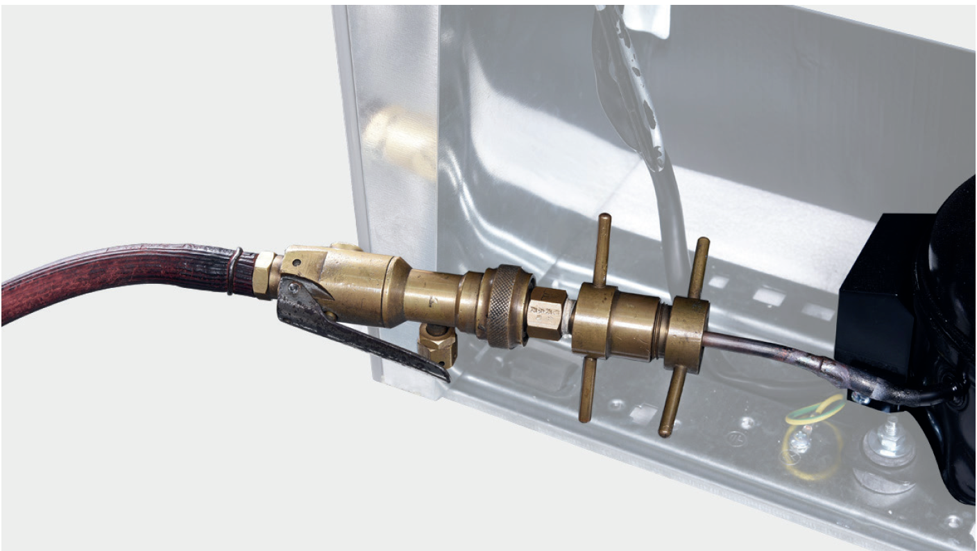
Install quick connector onto rebrazed pipe.
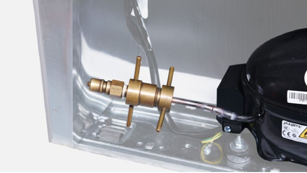
Step 6
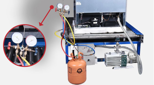
Inject nitrogen of 1.57Mpa through quick connector into pipe.

Step 7
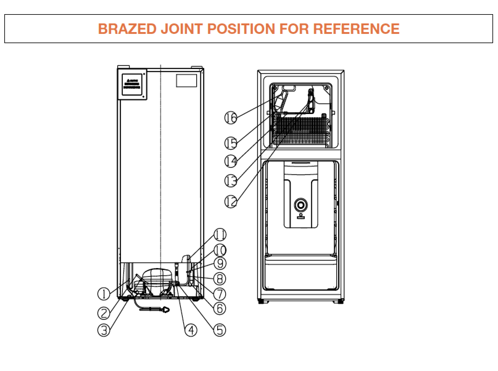
Leaking test for brazed joints in compressor niche.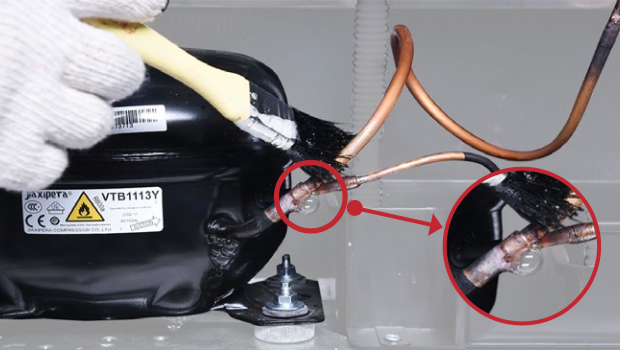

DIAGNOSIS 1

PROCEDURE 1
Step 1
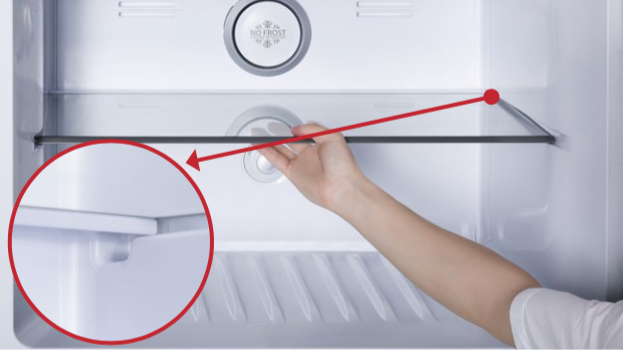
Remove freezer shelf.
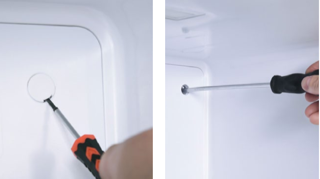
Step 2
Lever 2 screw covers off.
Step 3
Unscrew 2 screws.
Step 4
Remove air duct:a. Hold the decorative cover of air duct;
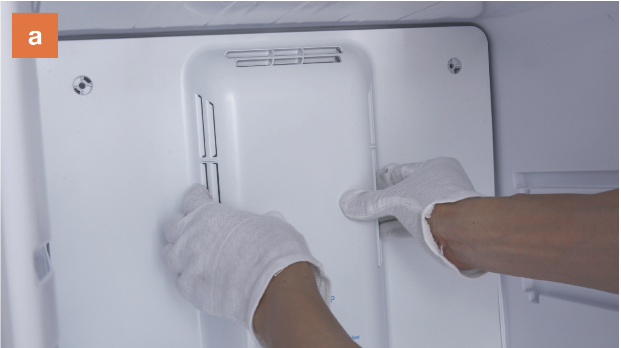
b. Disconnect the terminal
of fan motor;
b. Disconnect the terminal of fan motor;

c. Take air duct away.
c. Take air duct away.
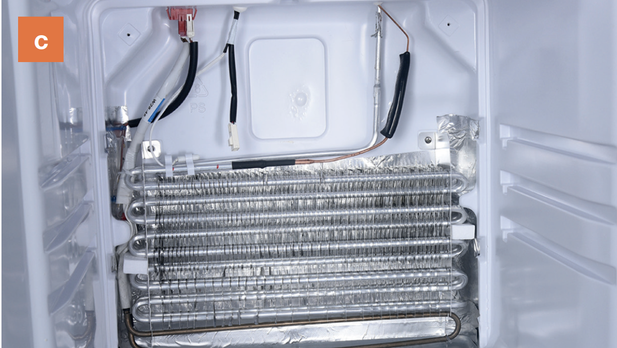
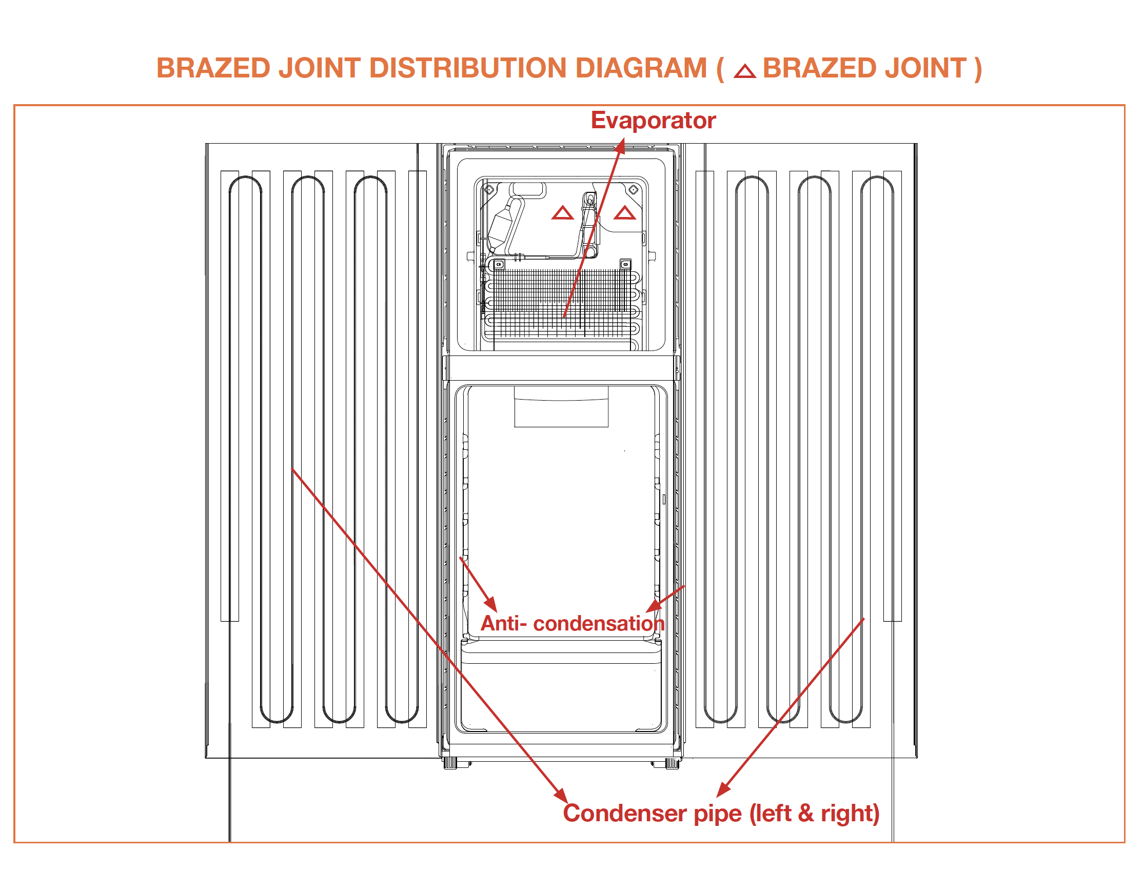
CHECK AND TEST 2
Follow indications in below drawing to test each brazed joint with soapy water in evaporator area behind freezer air duct.


PROCEDURE 2
Step 1
Clean paint off of brazed joint.
Step 2
Cut off brazed joint with
leaking.
Step 3
Use a bigger copper tube to connect 2 ends of brazed joint.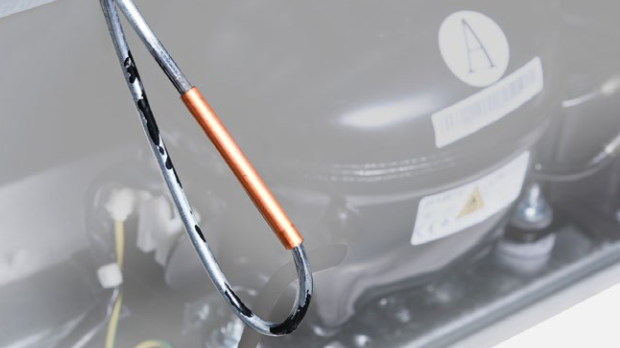
Step 4
Weld the 2 ends. Please get more details of brazing requirements on Annex B1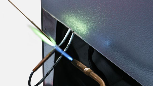
CHECK AND TEST 3
Step 1
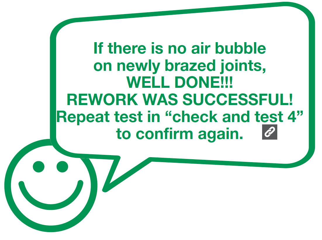
Inject 1.57Mpa nitrogen through quick connector into pipe and apply soapy water to test for leaks again.

CHECK AND TEST 4
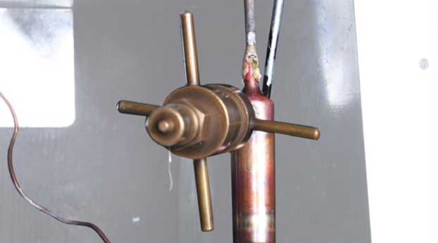
Step 1
Weld a piezometer onto processing tube of compressor.
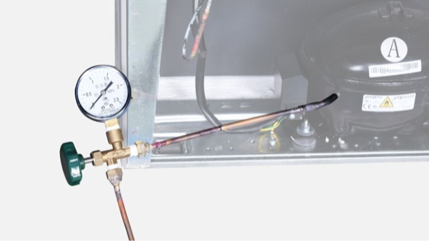
Step 2
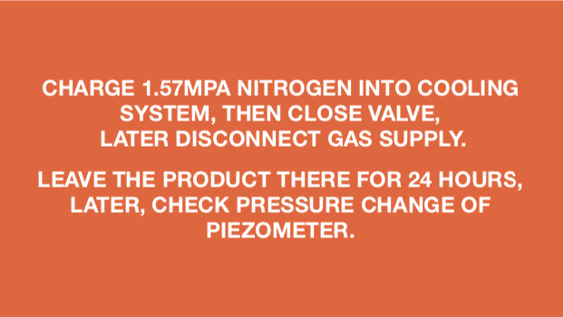
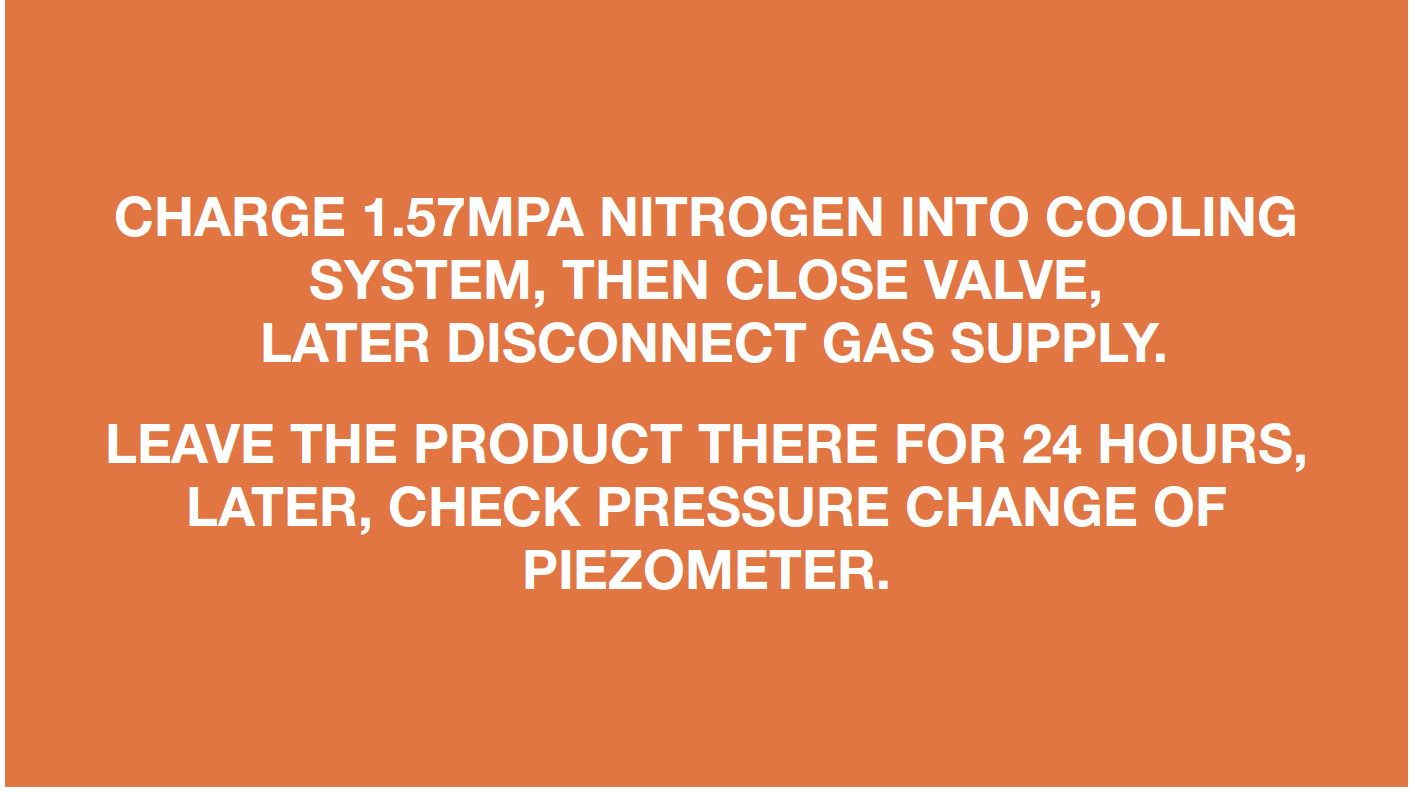
Charge nitrogen of 1.57Mpa through quick connector into pipe.
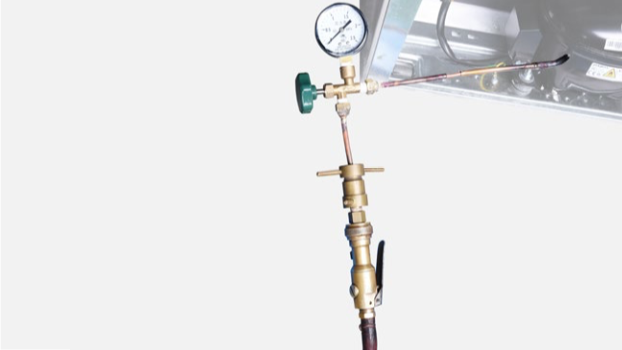
Step 3
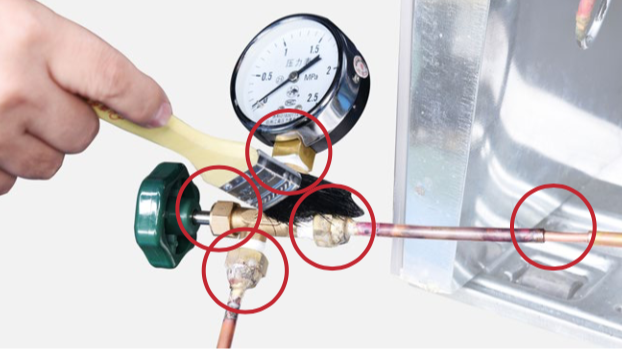
Perform leakage test on brazing points and piezometer.
DIAGNOSIS 4
CHECK AND TEST 5
Charge 1.57Mpa Nitrogen into cooling system, and then observe if there is rust and/or spotted holes on pipes of compressor niche and evaporator area.
If yes, please follow below procedures to do the check and rework.
Step 5
Inject nitrogen (1.57Mpa) through quick connector into pipe for at least 3 min to blow remaining refrigerant away.
DIAGNOSIS 5

PROCEDURE 3
Step 1
Clean paint off of brazed joint.
Step 2
Cut off brazed joint with leaking.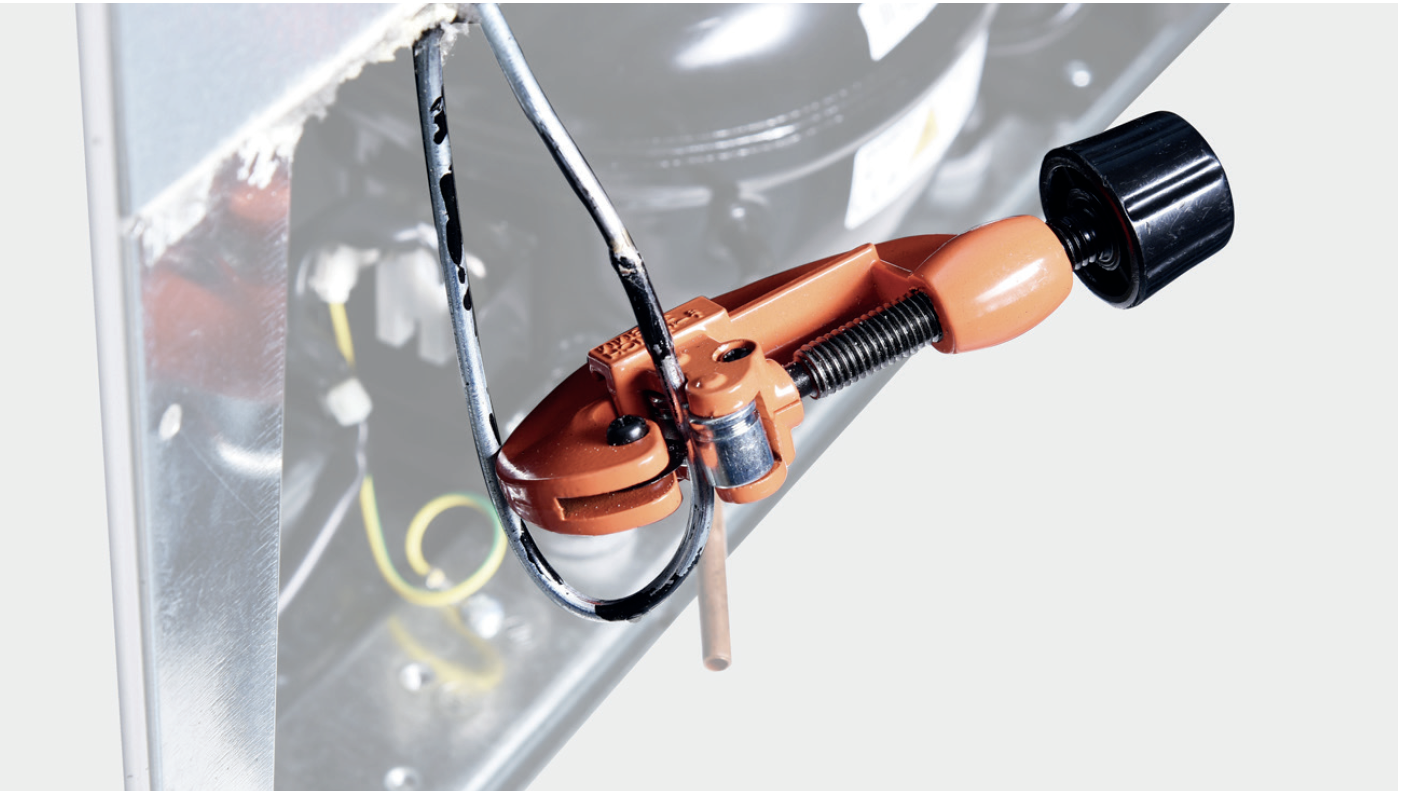
Step 3
Use a bigger copper tube to connect 2 endsof brazed joint.
Step 4
Weld the 2 ends.Please get more details of brazing
requirements on


CHECK AND TEST 6
Step 1
Inject 1.57Mpa nitrogen through quick connector into pipe and applysoapy water to test for leaks again.

DIAGNOSIS 6

PROCEDURE 4
Step 2
Cut off the brazed joint of drying filter.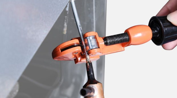
Step 3
Cut off capillary and remove the cut end by shaking.
Step 4
Weld a new drying-filter.
Step 5
Re-braze a copper tube onto processing tube of compressor.To get more details on brazing requirements,
please go to.
Step 6
Inject nitrogen (1.57Mpa) through quick connector into pipe for at least3 min to blow left remaining refrigerant.
Step 7
Add quick connector onto processing pipe of drying-filter.
Step 8
Do leaking test on brazed joints of drying-filter and processing pipe on compressor.
Step 9
Vacuum and recharge.
Click below link to get more details for vacuuming and gas- charging requirements, on Annex B1
Step 10
Block processing pipe twice by locking pliers.
Step 11
Leave locked pliers attached to second block and shake to cut off the remaining pipe.
Step 12
Weld the ends and remove the pliers.
PROCEDURE 5
Tip 1
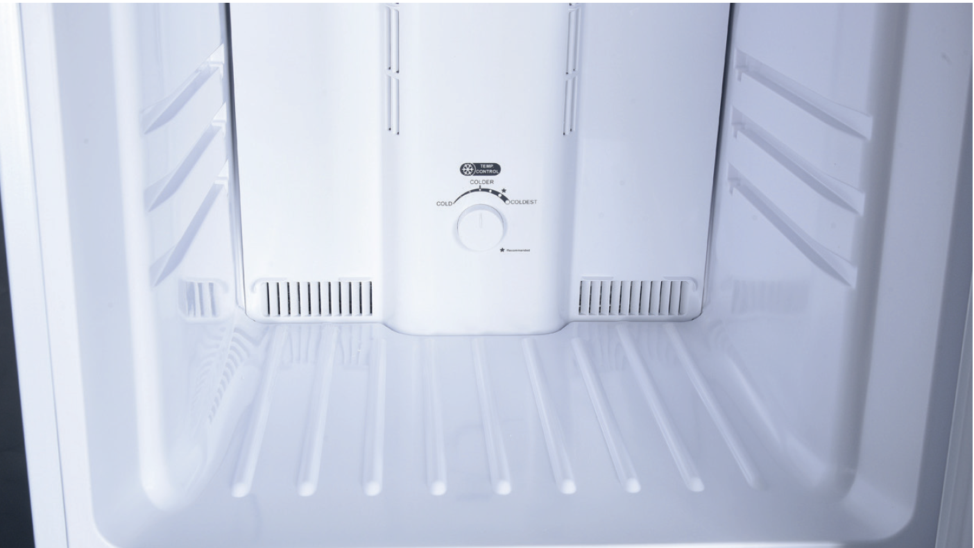
Firstly insert the air duct into the slot at thebottom.
Tip 2
When reinstalling air duct, move wires outof the way to prevent crushing with air duct.

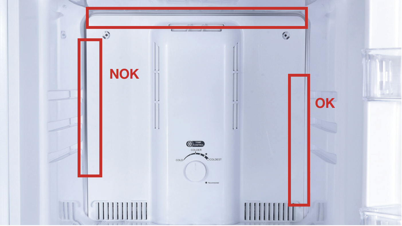
Tip 3
After pushing air duct back into position, youshould hear a clicking sound. If there is no
click, please repeat again.
DIAGNOSIS 7

GO BACK TO COMPONENT LIST