


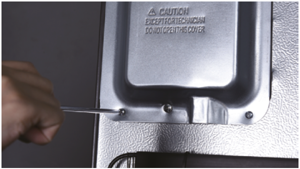
CHECK AND TEST 1
Step 1
Unscrew cover of
mainboard with a
cross-head screwdriver.
Step 2
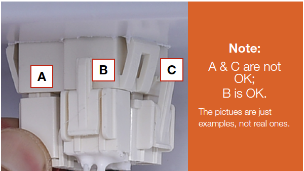
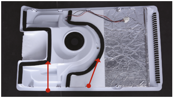
In mainboard area, check if terminal is inserted to proper final position.
If not, reinsert it to final position.
Note: the photos shown are just for example, they are not actual images of the product.

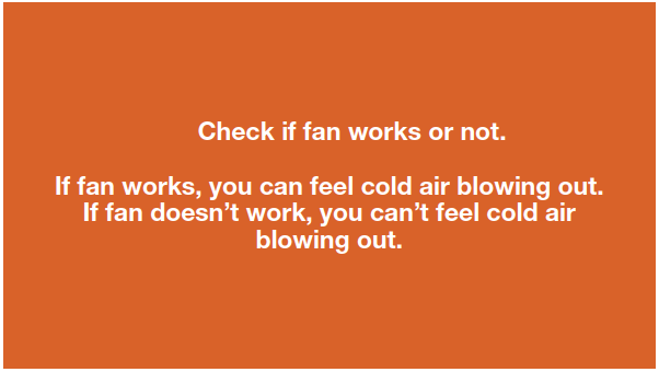
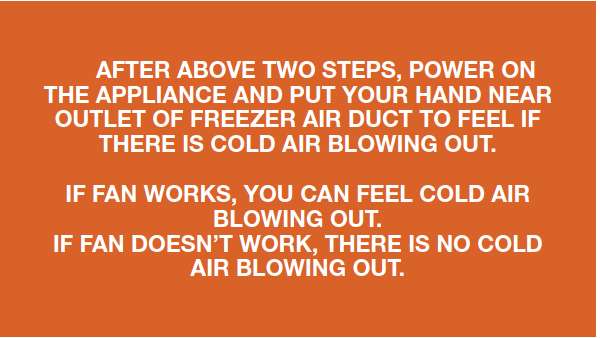
Step 3
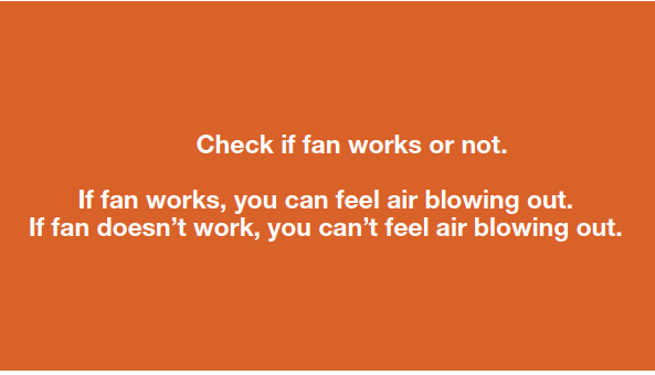
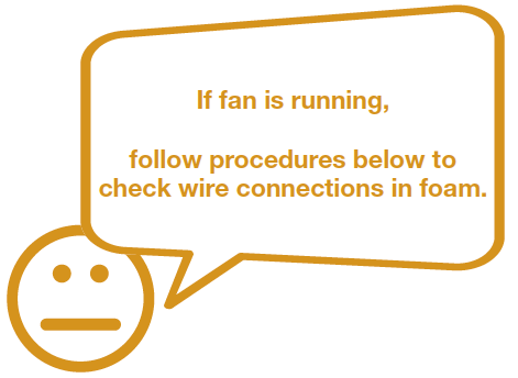
Power on the appliance, open the door, heat the temp. sensor and put your hand near outlet of air duct to feel if fan is blowing or not.

DIAGNOSIS 1


CHECK AND TEST 2
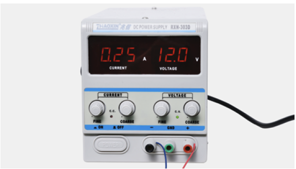
Step 1
Turn power output of transformer to DC 12V.
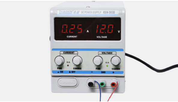
Step 2
Supply power from terminal in PCB area
(FAN & GND).

Step 3
Put your hand near outlet of freezer air duct to feel if fan is blowing or not.

DIAGNOSIS 2

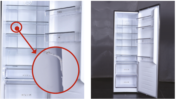
PROCEDURE 1
Step 1
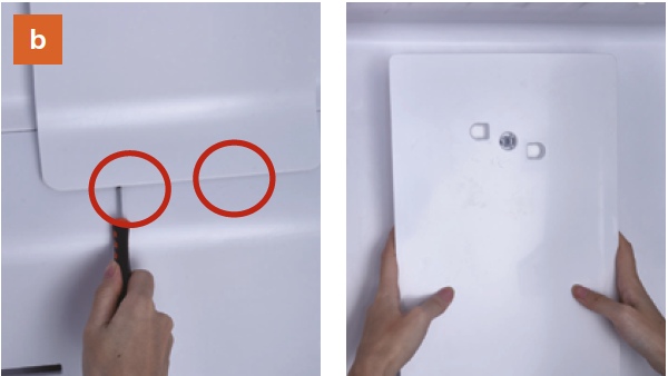
Remove all the drawers.

Step 2
Remove all glass shelves.

Step 3
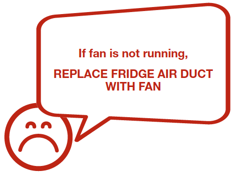
Remove the upper air duct.
a. prize up and remove the decorative cover.
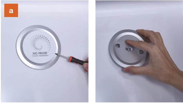
b. Prize up the buckle on the air duct with
slotted screwdriver, then remove the upper
air duct.
Step 4
Dismantle the air duct.a. Unscrew the screws (total four) with
Cross-head screw driver.
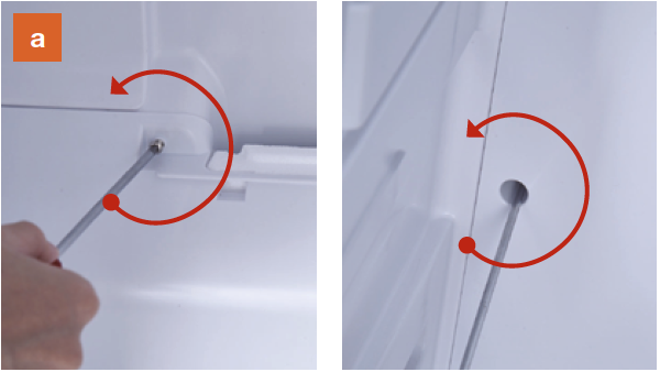
b. Catch the lower air duct and pull down
the air duct.

c. Pay attention to the connectors when
pulling out the air duct.

d. Disconnect the terminal for fan motor.
Disconnect the terminal for defrost sensor.

e. Move the air duct out of the freezer compartment.


CHECK AND TEST 3
Step 1
In duct area, check if terminal is pushed into
final position. If not, reconnect it.
Step 2
Check whether terminal is filled with foam.
If yes, please use tweezers to clean and
remove the foam, and reconnect it again.

DIAGNOSIS 3

CHECK AND TEST 4
Step 1
Check if wires of fan motor are damaged or not.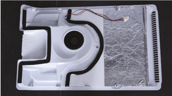
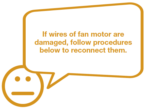

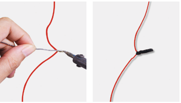
PROCEDURE
Step 1
Cut wire off.
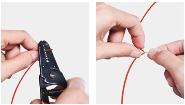
Step 4
Tin soldering.Step 5
Cover connection with electrical tape.

CHECK AND TEST 5
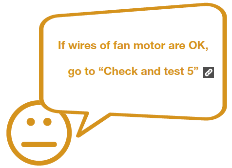
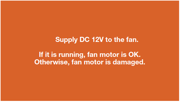
Step 1
Set output of transformer to DC 12V to test fanfrom the terminal behind the air duct.
Step 2
testo testo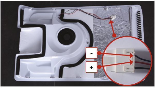
DIAGNOSIS 5
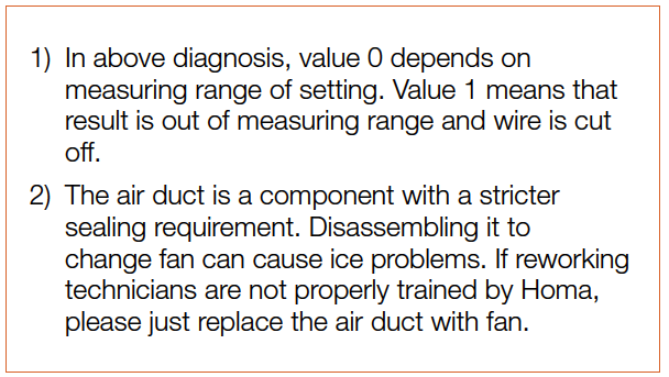
NOTE
CHECK AND TEST 6
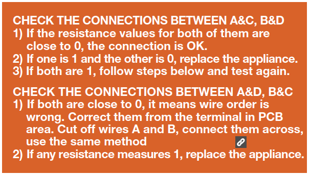
Step 1
Set multimeter to resistance gear.
Step 2
Put one detector into end of wires in PCB area,and another detector into end of wires behind
air duct.

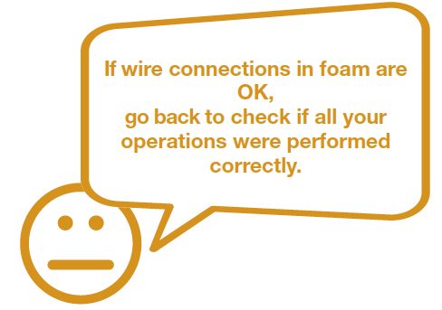
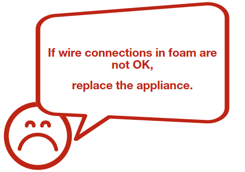
DIAGNOSIS 6
NOTE
PROCEDURE 3
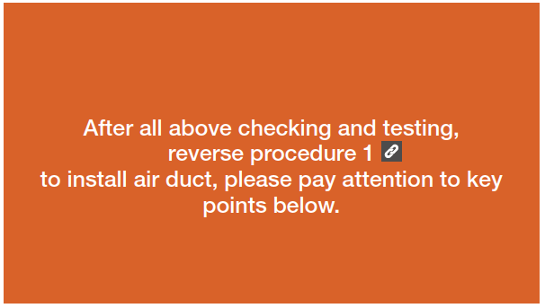
Tip 1
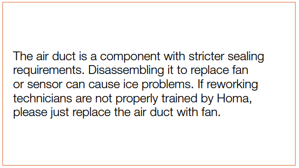
Make sure the sealing sponges are in goodcondition.
Tip 2
After pushing air duct into place, you shouldhear clicking sounds at 8 buckle positions. If not, repeat again.
Tip 3
Check to see if there is a wide gap between air
duct and cabinet. If there is, reinstall air duct.


GO BACK TO COMPONENT LIST