

CHECK AND TEST 1
Step 1
Unscrew cover of
mainboard with a
Cross-head screwdriver.
mainboard with a
Cross-head screwdriver.

Step 2
In mainboard area, chec if terminal is pushed into proper final position.
If not, reinsert it to final position.
Note: the photos shown are just for example, they are not actual images of the product.

Step 3
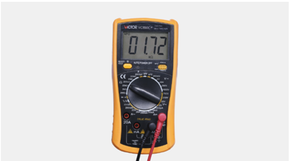
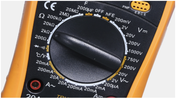
Set multimeter to resistance gear.
Step 4
Measure resistance of fridge temp. sensor fromterminal in PCB area.

Step 5
testo testo
Step 6
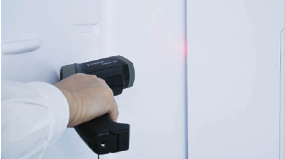
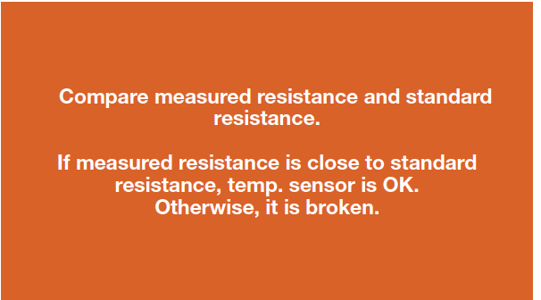
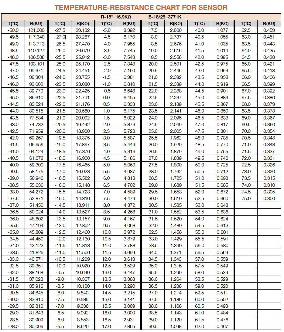
Measure the temperature of fridge temp. sensor.Use the measured temperature to find the
standard resistance value in Temperature-
Resistance Chart for Sensor.

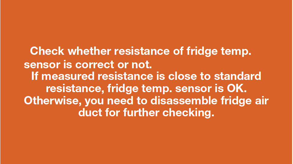
DIAGNOSIS 1


Step 2
Remove shelves.

Step 3
Remove the upper air duct.
a. prize up and remove the decorative cover.
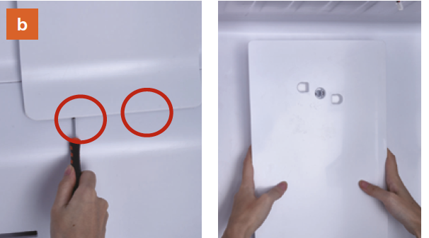

CHECK AND TEST 2
Step 1
Check if wires of fridge temp. sensor are
damaged or not.
if so, reconnect it.

Step 2
Cut off wires.
Step 3
Measure the resistance of fridge sensor from terminal in fridge air duct cover and record the value.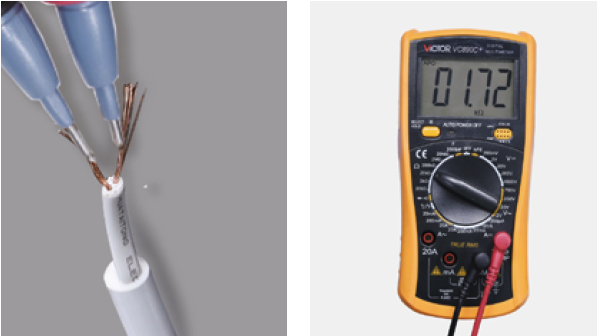
DIAGNOSIS 2


PROCEDURE 2

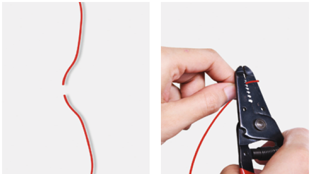
Step 1
Cut wire off.
Step 2
Peel off the sleeves.
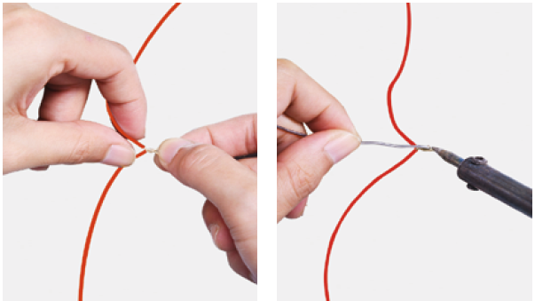
Step 3
Check to ensure proper wire order and reconnect them.
Step 4
Tin soldering.
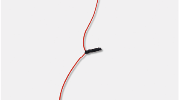
Step 5
Cover connecting point
with electrical tape.


PROCEDURE 3
CHEK AND TEST 4

DIAGNOSIS 4


GO BACK TO COMPONENT LIST