

CHECK AND TEST 1
Step 1
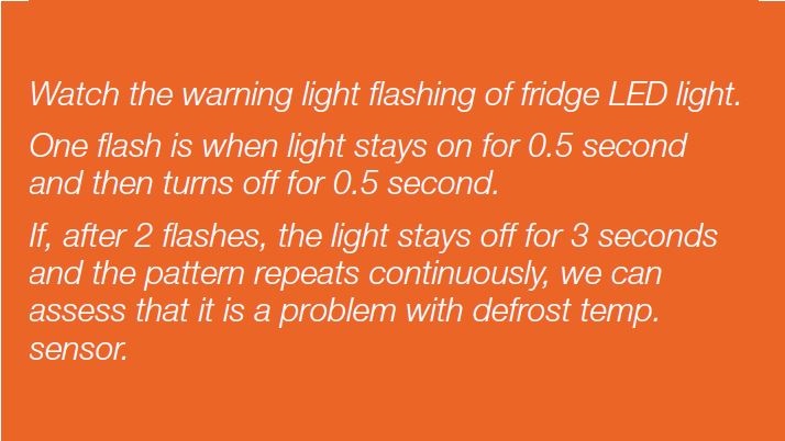
Check the flashing
times of LED.
Note

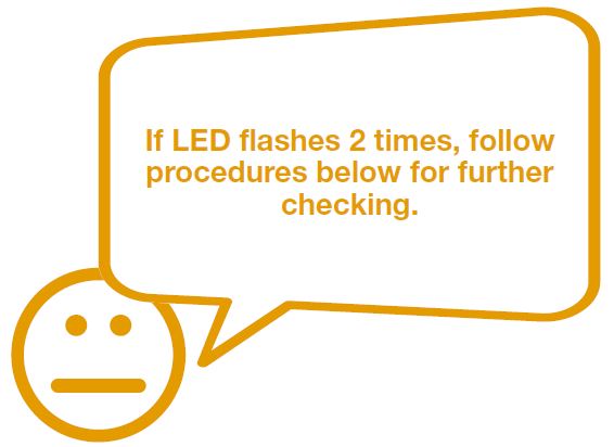
DIAGNOSIS 1


CHECK AND TEST 2
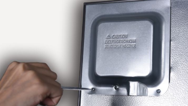
Step 1
Unscrew cover of
mainboard with a
Cross-head screwdriver.
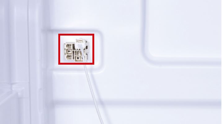
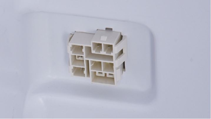
Step 2
Check if terminal in PCB
area is pushed to final
position.
If not, reinsert it to final
position.

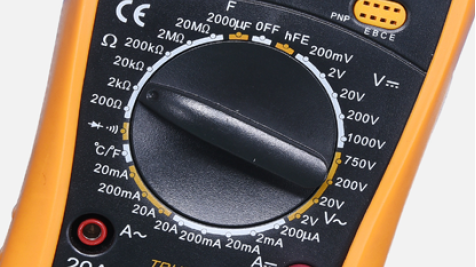
Step 3
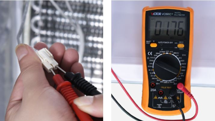
Set multimeter to
resistance gear.
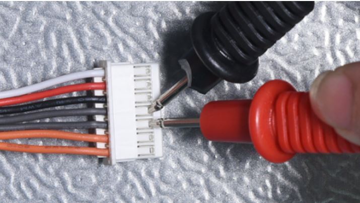
Step 4
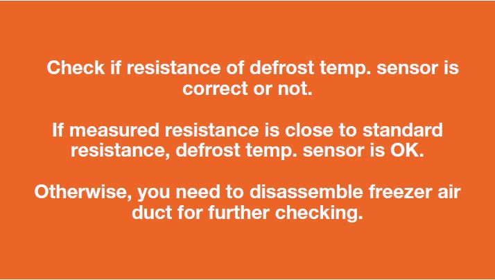
In PCB area, measure the
resistance of defrost temp.
sensor with a multimeter.
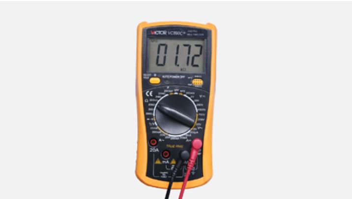
Step 5
Take note of value.
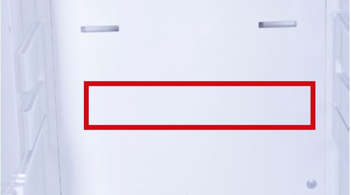
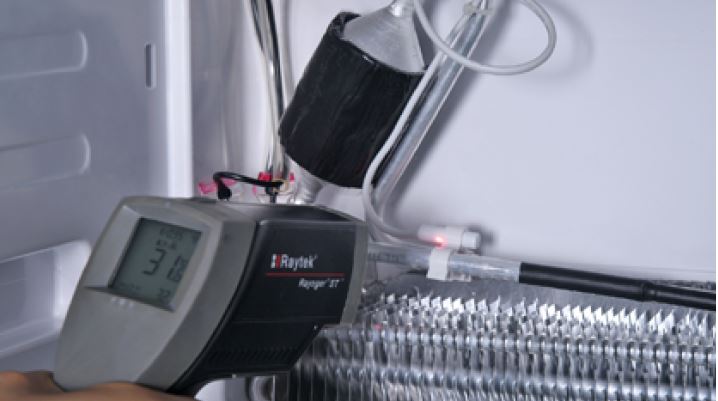
Step 6
Measure the temperature
of air duct, near the defrost
temp. sensor.
Use measured temperature
to find the standard
resistance value in
Temperature-Resistance
Chart for Sensor.
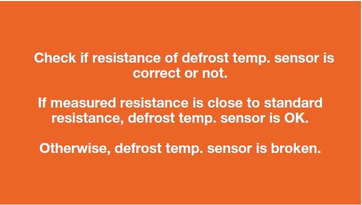
DIAGNOSIS 2


PROCEDURE 1

Step 1
Remove all drawers.
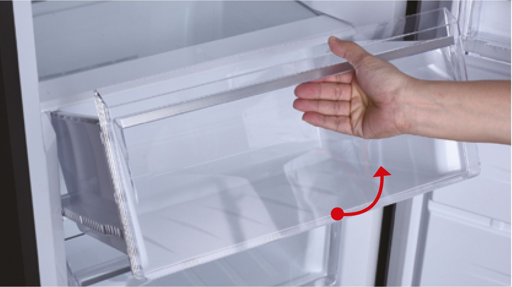
Step 2
Remove all glass
shelves.
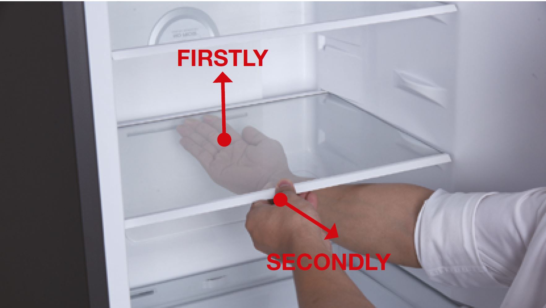
Step 3
Remove the upper air
duct.
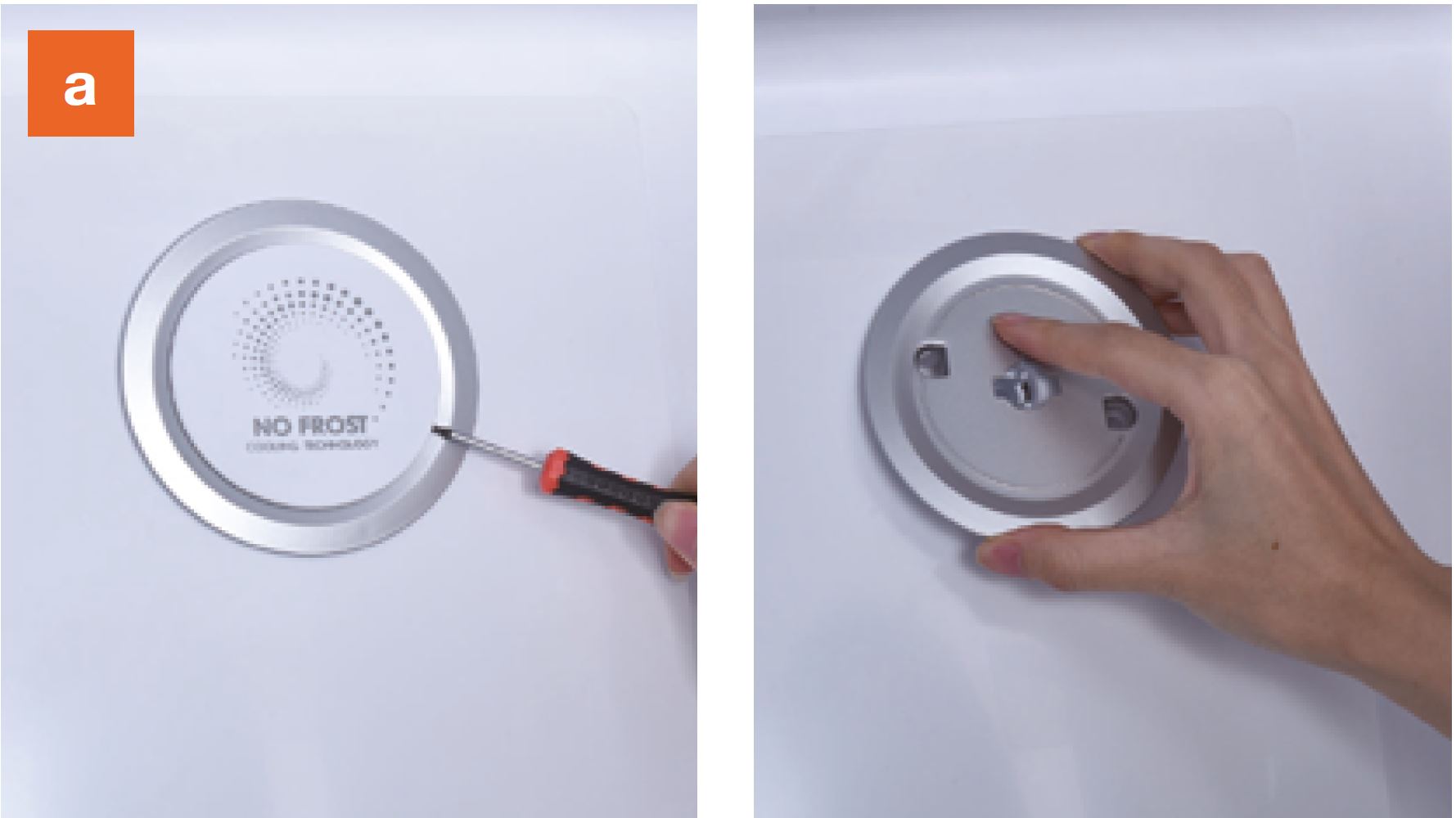
a. Prize up and remove the decorative cover.
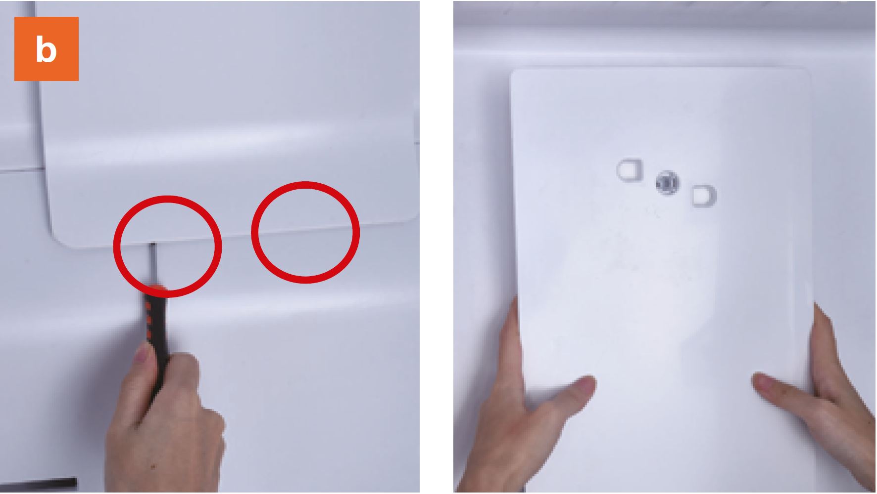
b. Prize up the buckle
on the air duct with slotted
screwdriver, then remove
the upper air duct.
b. Prize up the buckle
on the air duct with slotted
screwdriver, then remove
the upper air duct.
screwdriver, then remove
the upper air duct.
Step 4
Dismantle the air duct.
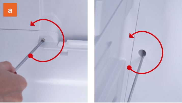
a. Unscrew the screws
(total four) with
Cross-head
screwdriver.
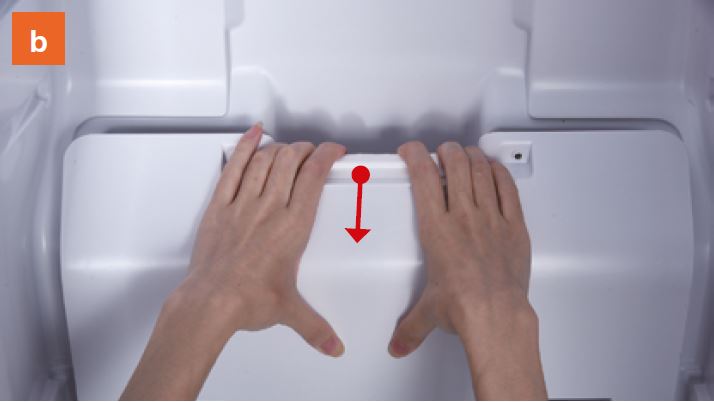
b. Catch the lower
air duct and pull down
the air duct.
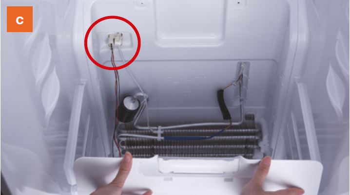
c. Pay attention to the
connectors when
pulling out the air
duct.
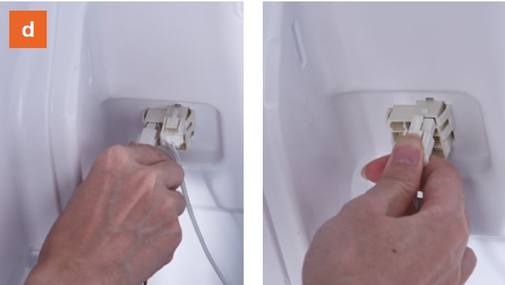
d. Disconnect the
terminal for fan motor.
Disconnect the
terminal for defrost
sensor.
e. Move the air duct
out of the fridge
compartment.
Step 4
Dismantle the air duct.
a. Unscrew the screws
(total four) with
Cross-head
screwdriver.
b. Catch the lower
air duct and pull down
the air duct.
c. Pay attention to the
connectors when
pulling out the air
duct.
d. Disconnect the
terminal for fan motor.
Disconnect the
terminal for defrost
sensor.
e. Move the air duct
out of the fridge
compartment.

CHECK AND TEST 3
Step 1
Check if terminal is
inserted to final position.
If not, please re-insert it
to final position.
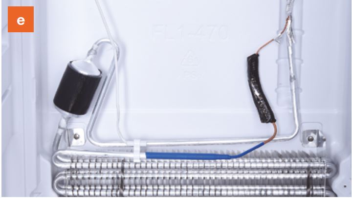
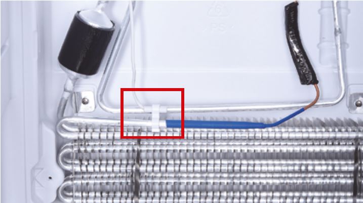
Step 2
Check if sensor is
attached in proper
position, as shown in
picture.
If not, correct it.
Step 3
Check if wire of defrost
sensor is broken.
IF YES, REPLACE IT
WITH A NEW ONE.
Step 4
Disconnect terminal of
defrost temp. sensor.
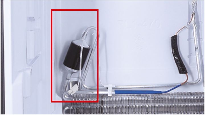
Step 5
Check if the terminal is
stuffed with foam.
If so, use tweezers to
smash it and remove.
Step 6
Measure resistance of
defrost temp. sensor
from terminal in fridge,
and take note of it.
Step 7
of defrost temp. sensor.
DIAGNOSIS 3
CHECK AND TEST 4
Step 1
Set multimeter to
resistance gear.
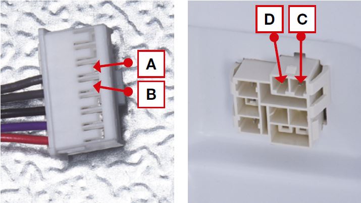
Step 3
Put detector into one
end of wires in PCB area.
Put another detector into
end of wires behind air duct.
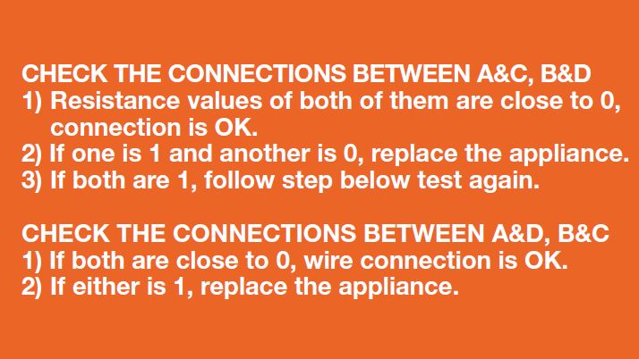
DIAGNOSIS 5

PROCEDURE 2

Step 1
Unscrew cover of mainboard with a Cross-head screwdriver.
Step 2
Disconnect terminals.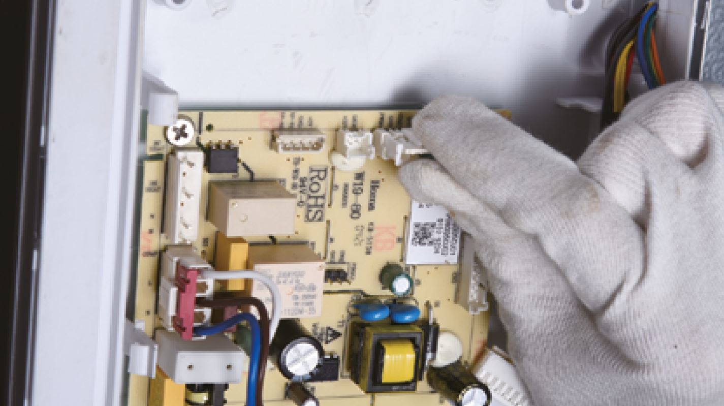
Step 3
Prize up the buckle and
disconnect the terminal.

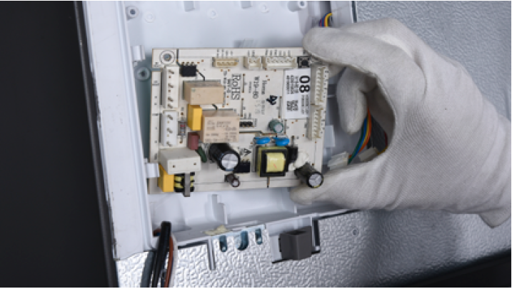
Step 4
Unscrew the mainboard.

Step 5
Remove the mainboard.Reverse steps above
to install a new
mainboard.
DIAGNOSIS 5


PROCEDURE 3
Tip 1
Make sure the sealing
sponges are in good
condition.
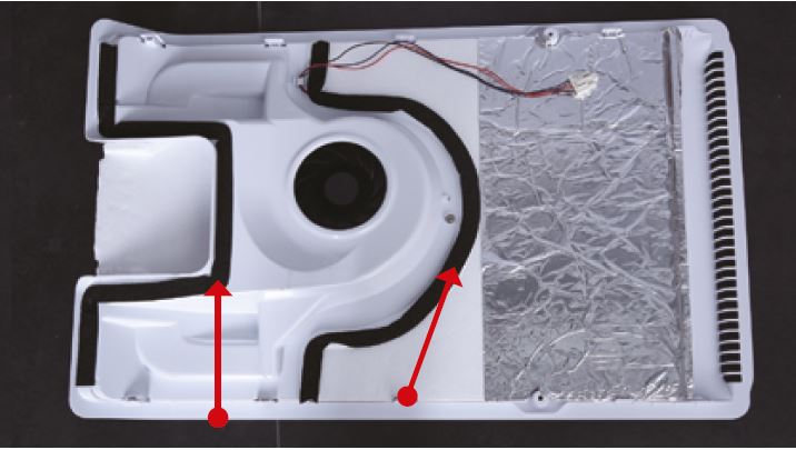
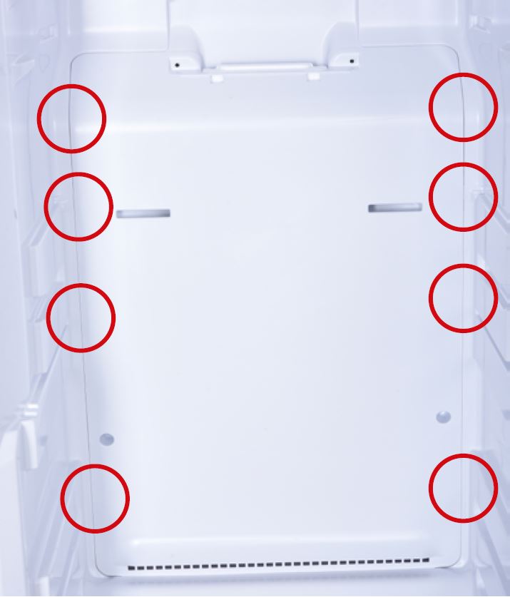
Tip 2
After pushing air duct
into place, you should
hear clicking sounds at 8
buckle positions. If not,
repeat again.
Tip 3
Check to see if there is
a wide gap between air
duct and cabinet. If there
is, reinstall air duct.

GO BACK TO COMPONENT LIST