

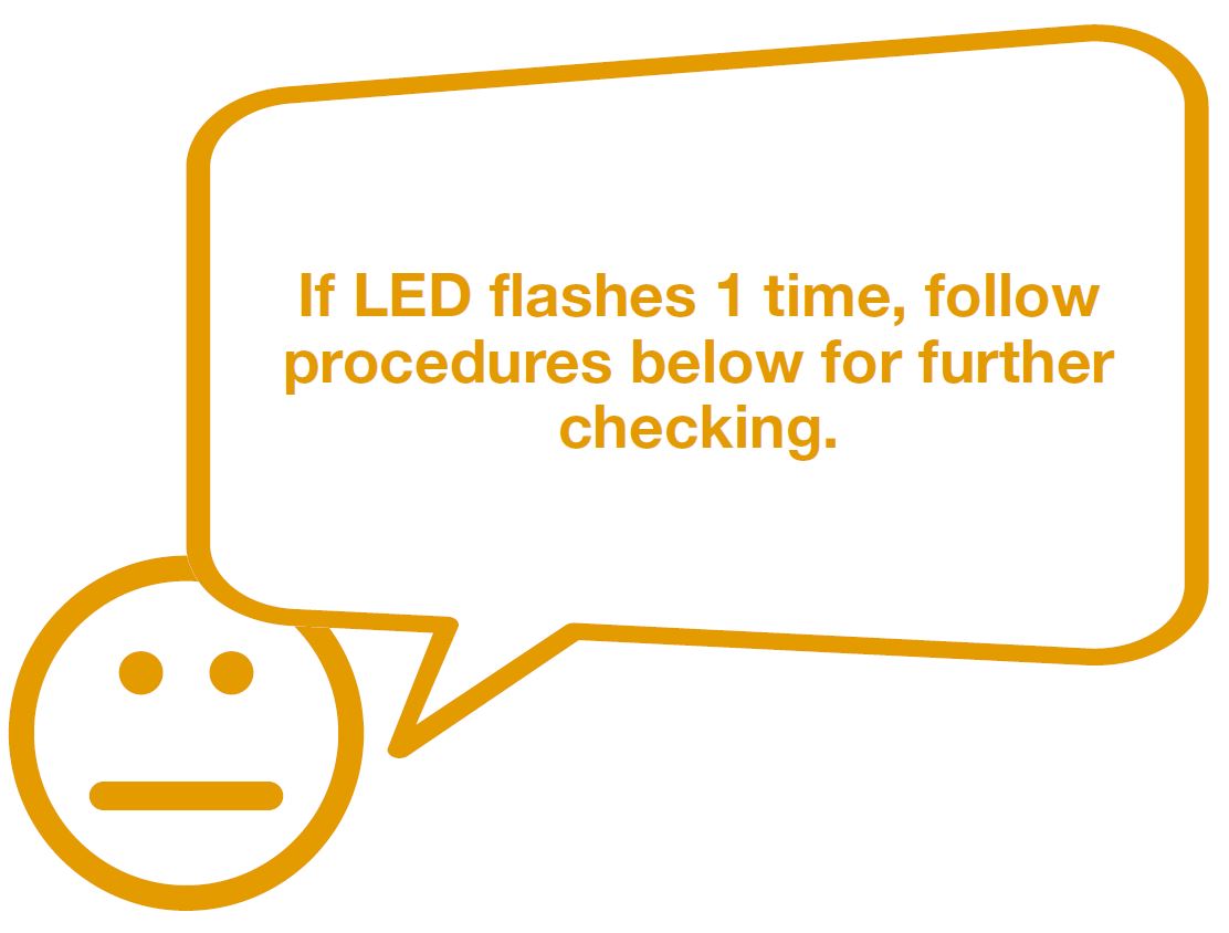
CHECK AND TEST 1
Step 1
Check the flashing
times of LED.
Note
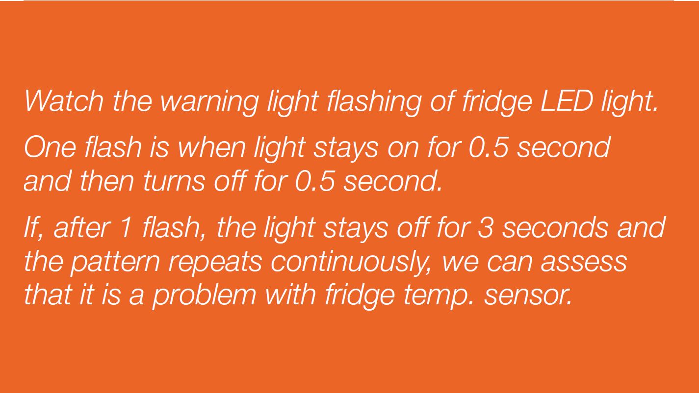

DIAGNOSIS 1


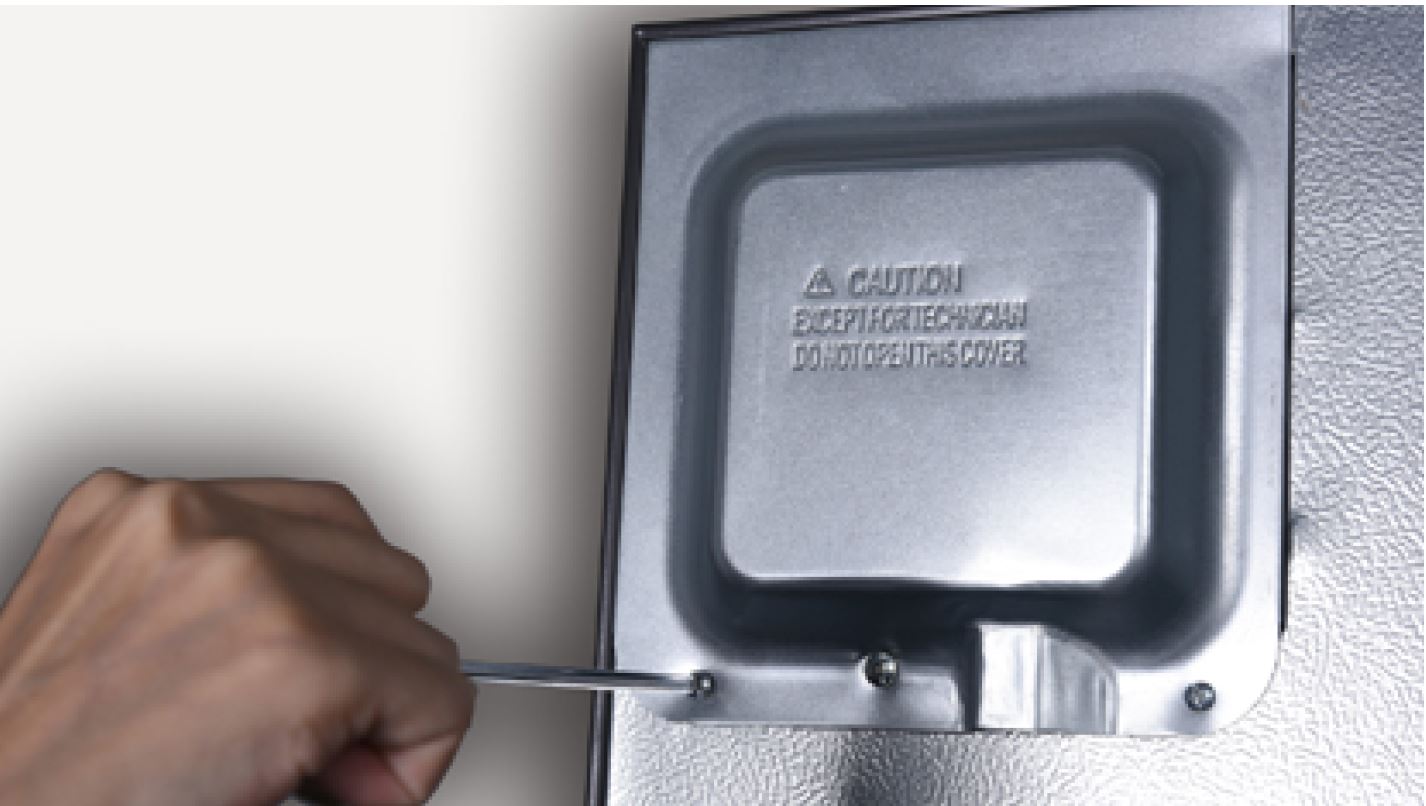
CHECK AND TEST 2
Step 1
Unscrew cover of
mainboard with a
Cross-head screwdriver.
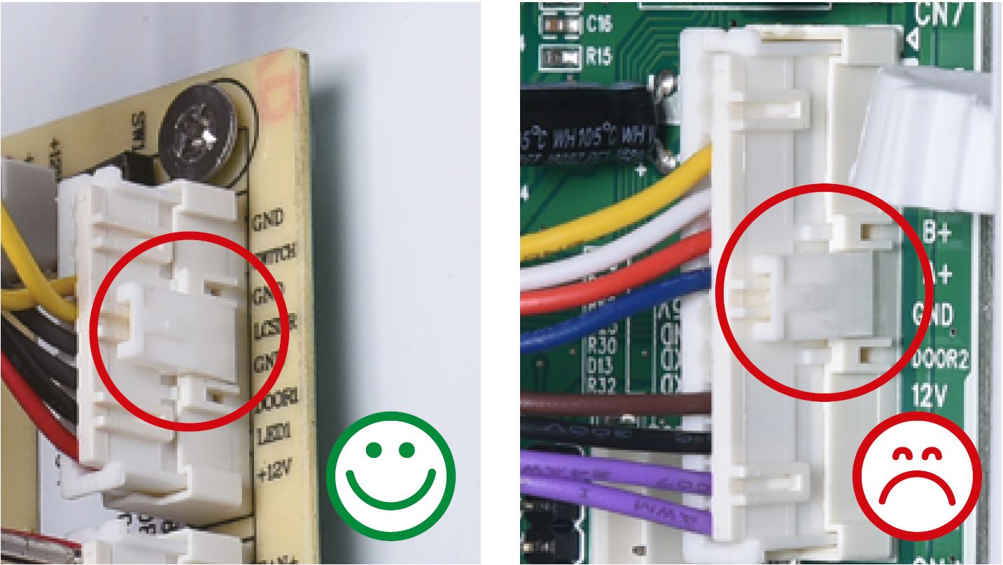
Step 2
In mainboard area, check
if terminal is pushed into
proper final position.
Note: the photos shown
are just for example,
they are not actual
images of the product.
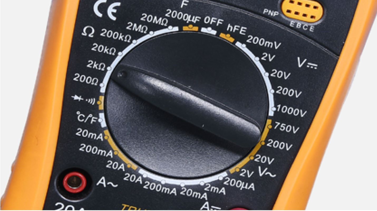
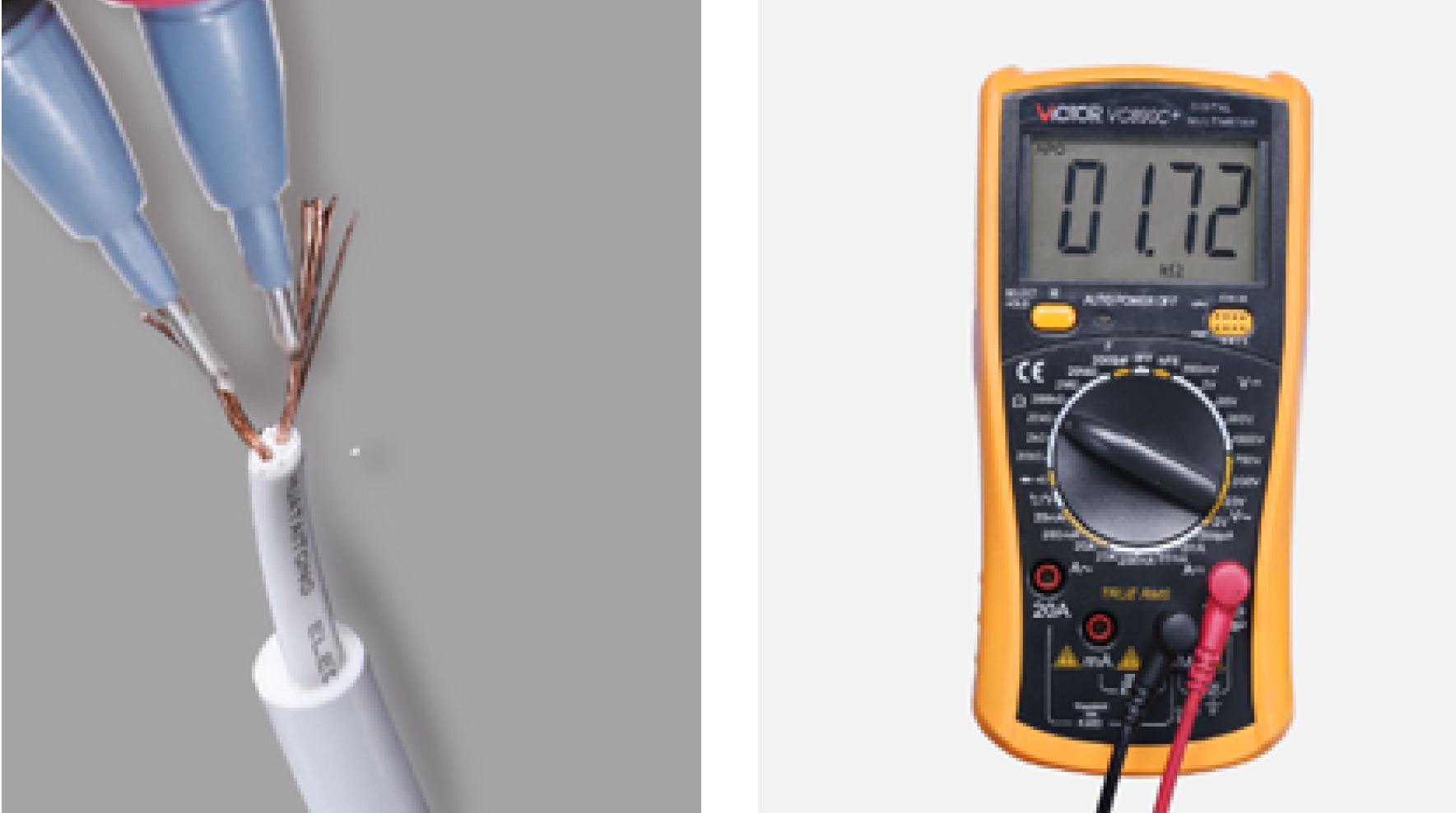
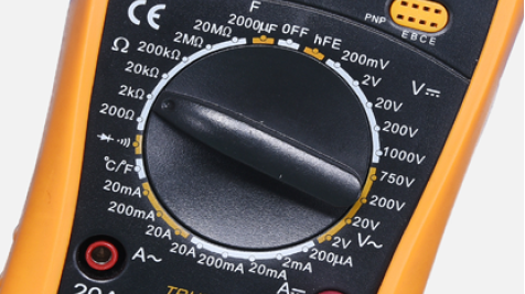
Step 3
Set multimeter to
resistance gear.
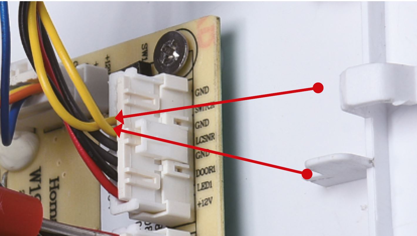
Step 4
Measure resistance of
fridge temp. sensor from
terminal in PCB area.
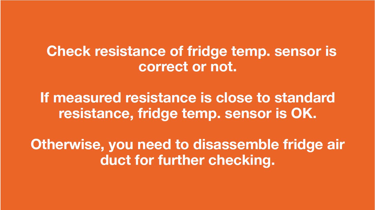
Step 5
Take note of value.
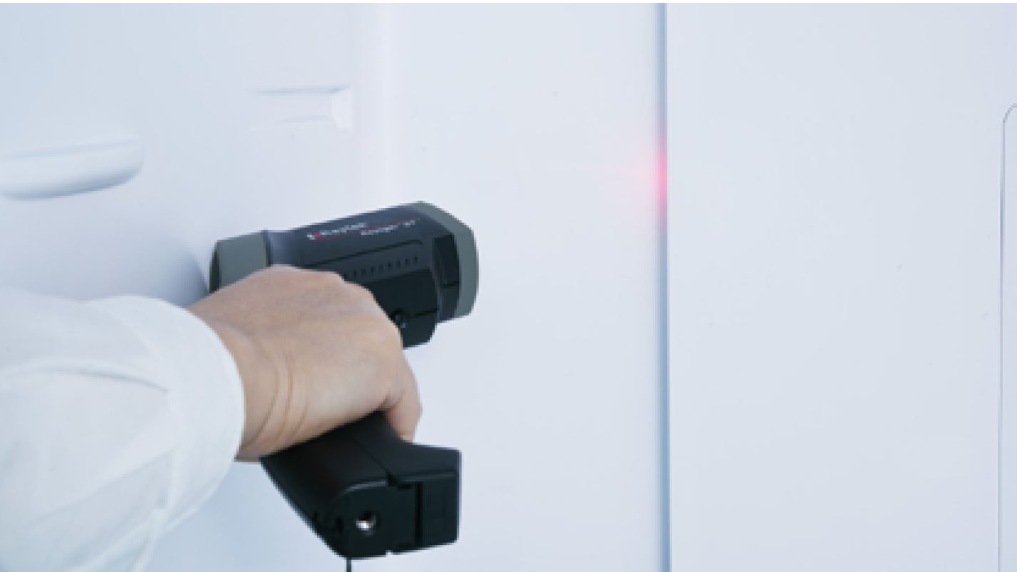
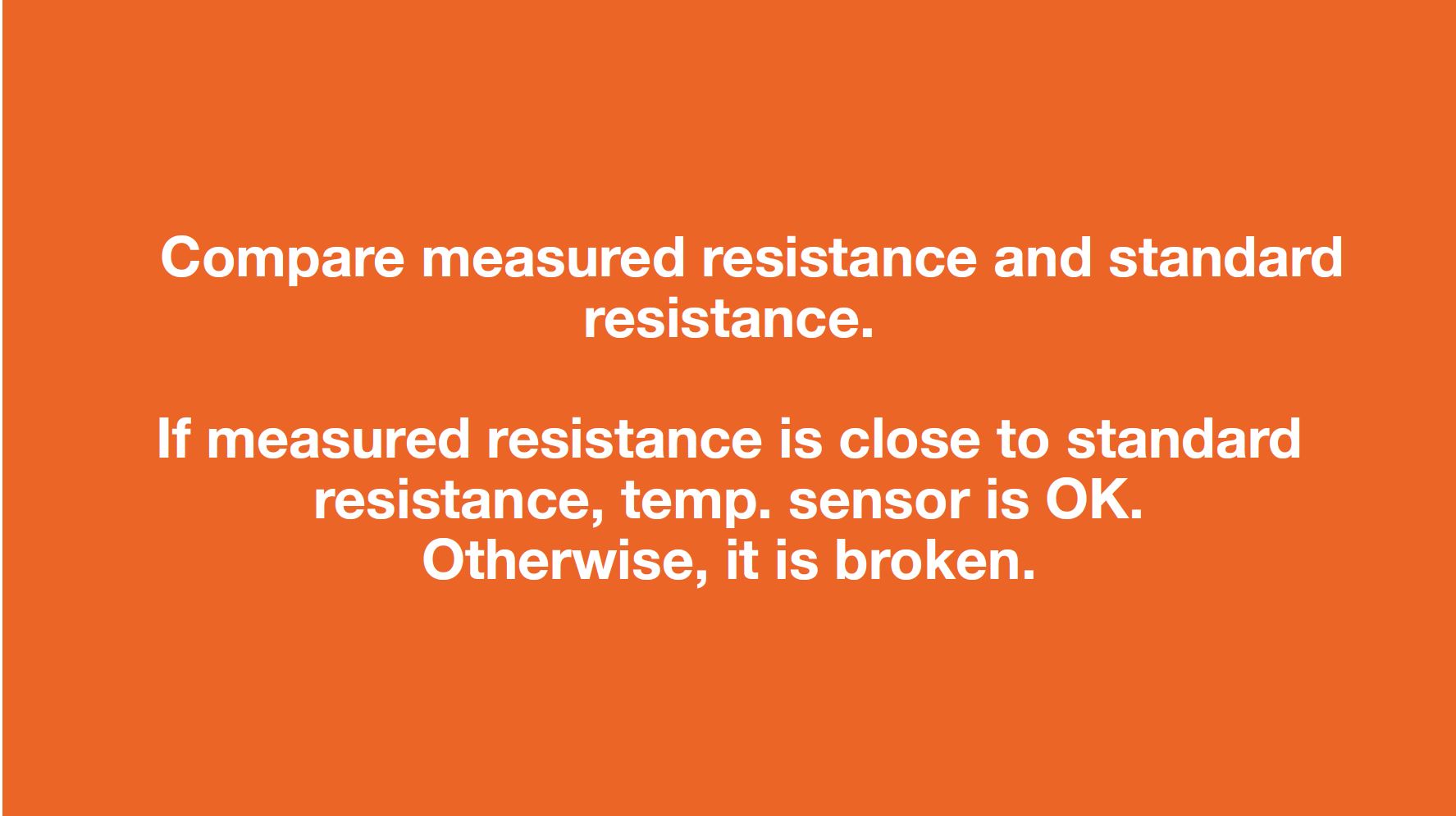
Step 6
Measure the temperature
of fridge temp. sensor.
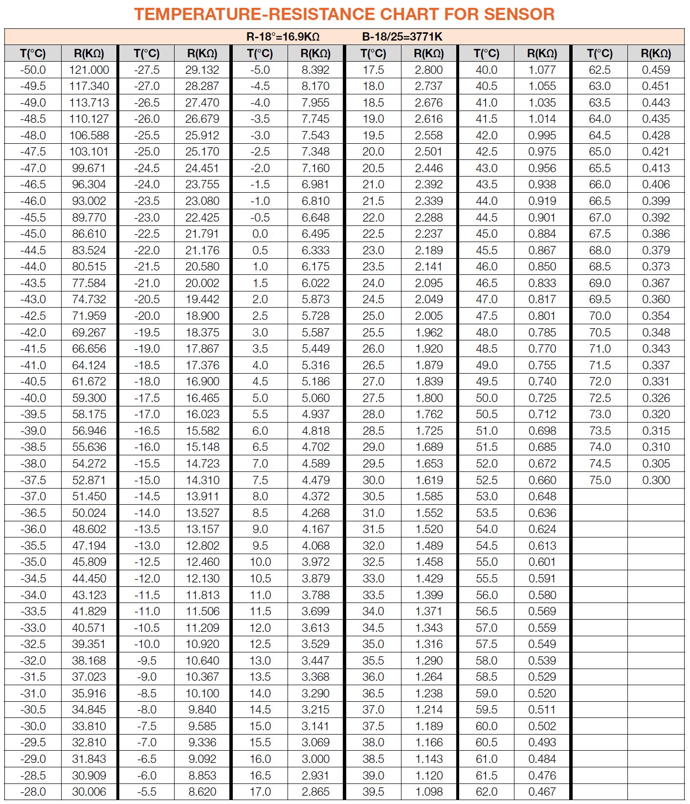
Use the measured
temperature to find the
standard resistance
value in Temperature-
Resistance Chart for
Sensor.
DIAGNOSIS 2
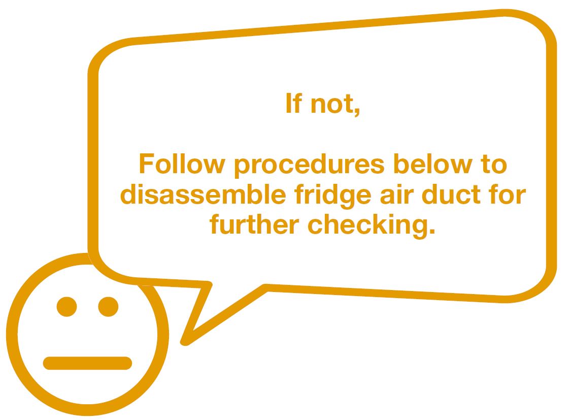

PROCEDURE 1

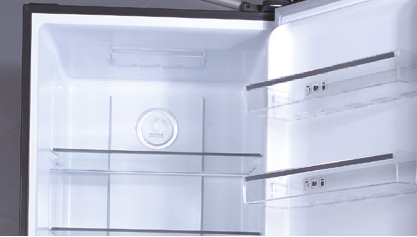
Step 1
Remove crispers.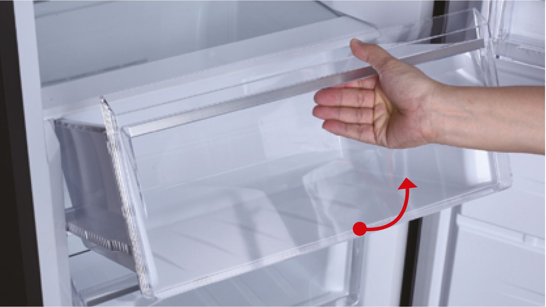
Step 2
Remove shelves.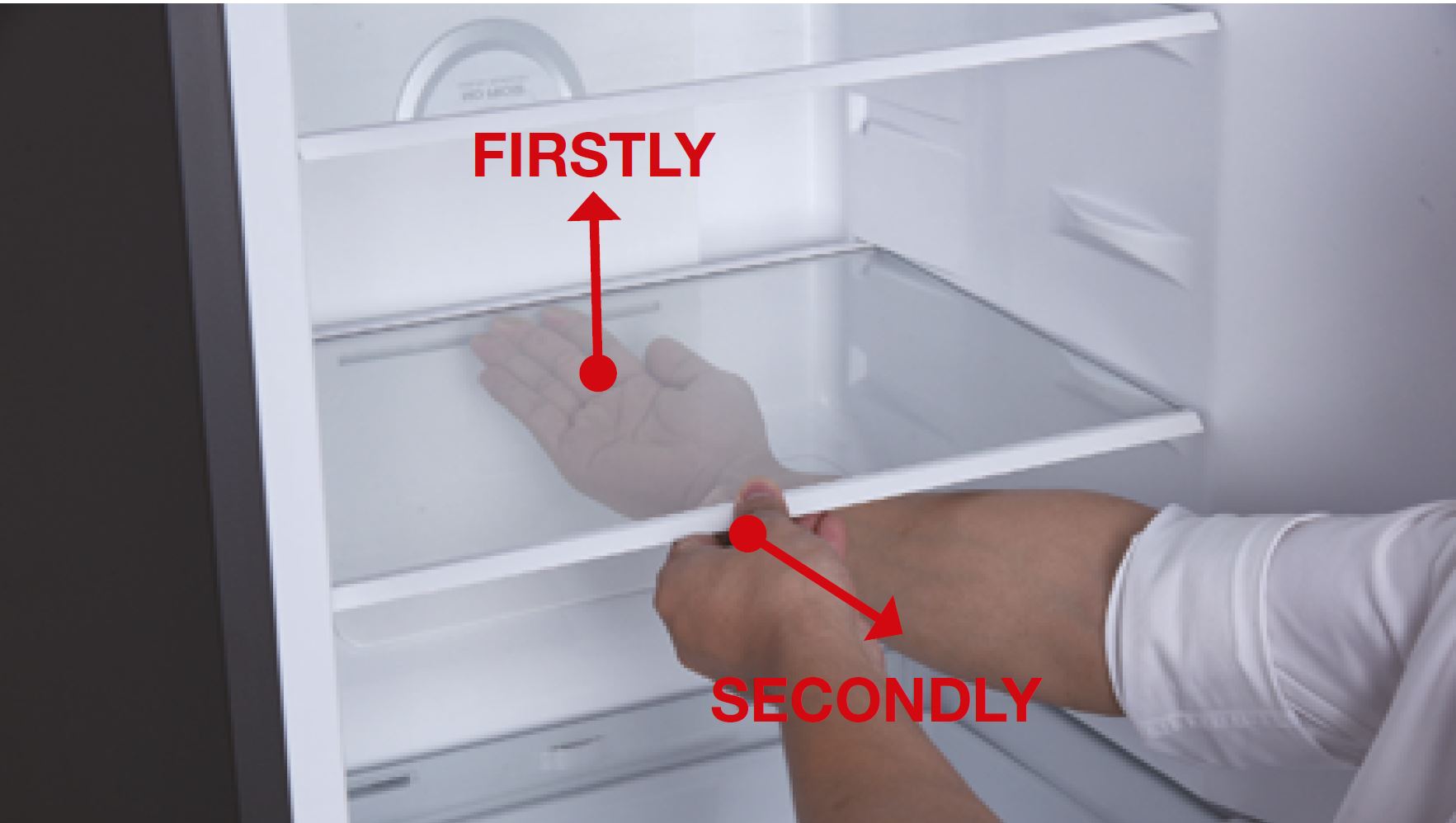
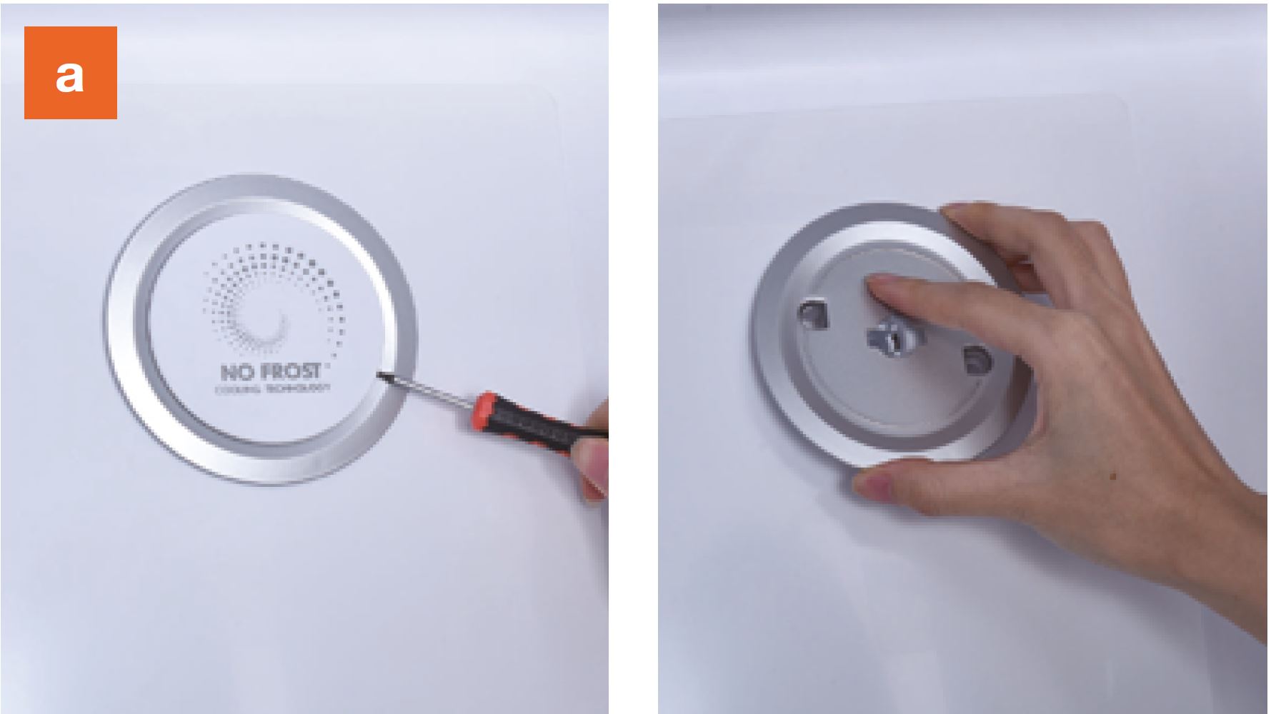
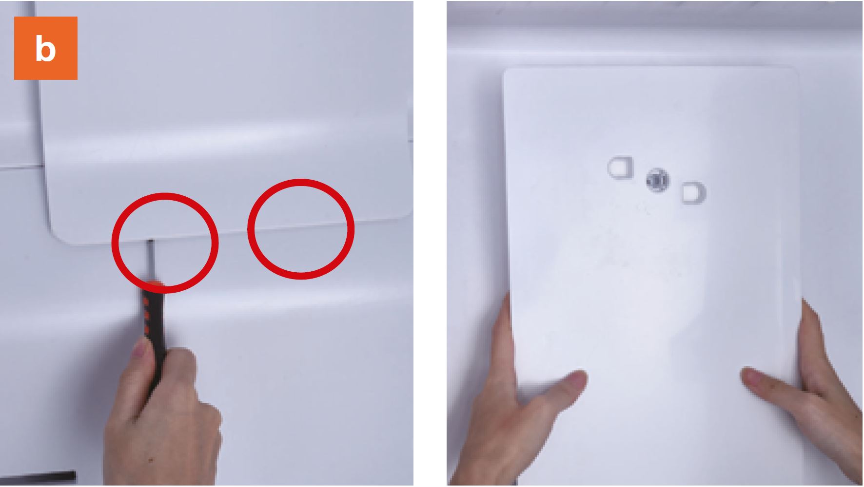
Step 3
Remove the upper air
duct.
a. Prize up and remove
the decorative cover.
b. Prize up the buckle
on the air duct with slotted
screwdriver, then remove
the upper air duct.
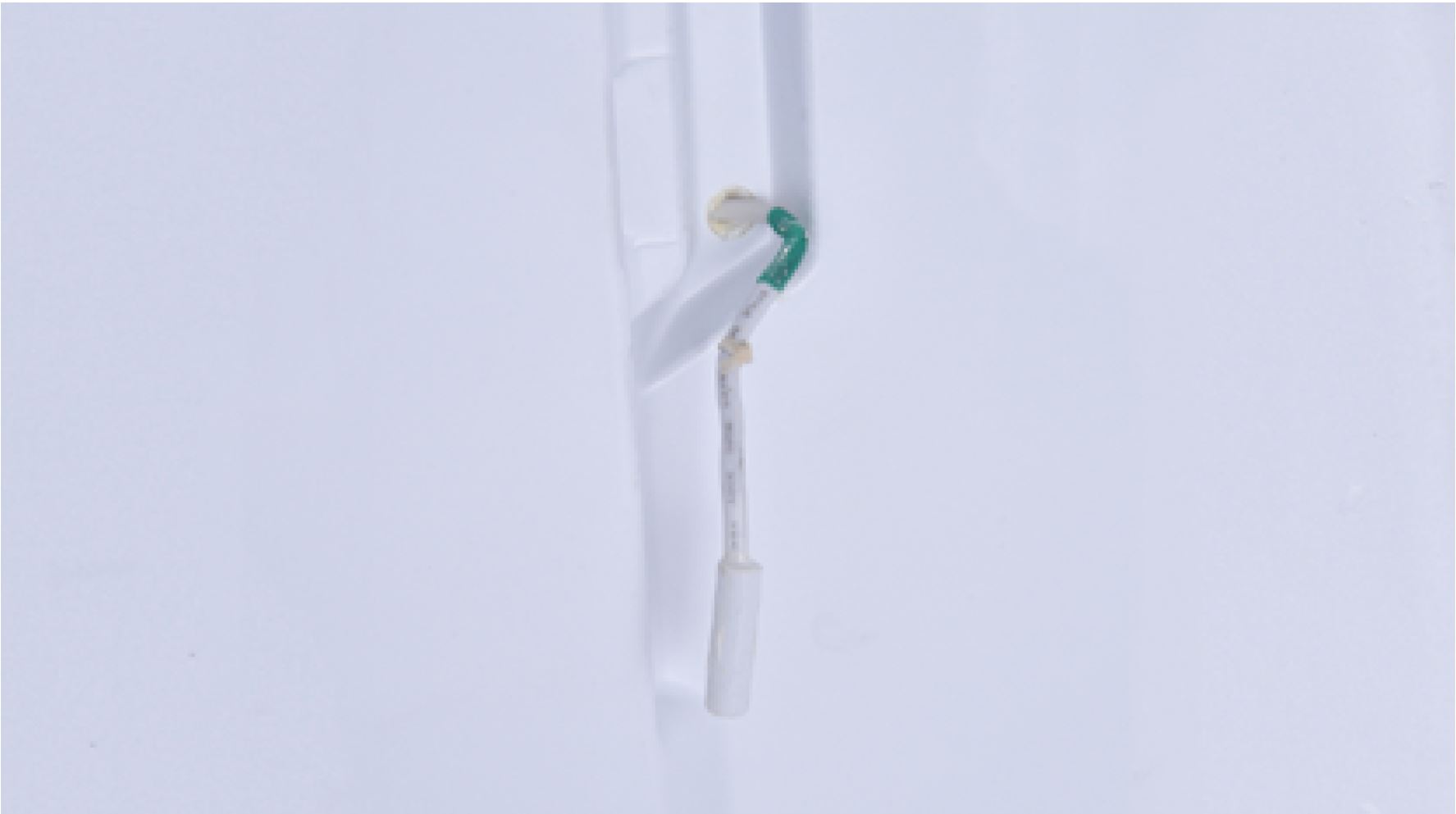
CHECK AND TEST 3
Step 1
Check if wires of fridge
temp. sensor are
damaged or not.
if yes, reconnect it.
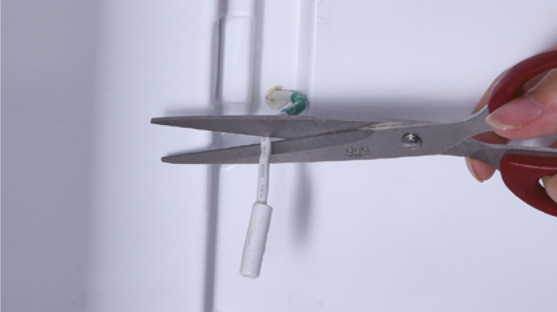
Step 2
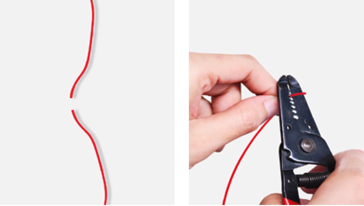
Cut off wires.Step 3
Measure the resistance of
fridge sensor from terminal
in fridge air duct cover and
record the value.
DIAGNOSIS 3


PROCEDURE 2

Step 1
Cut wire off.Step 2
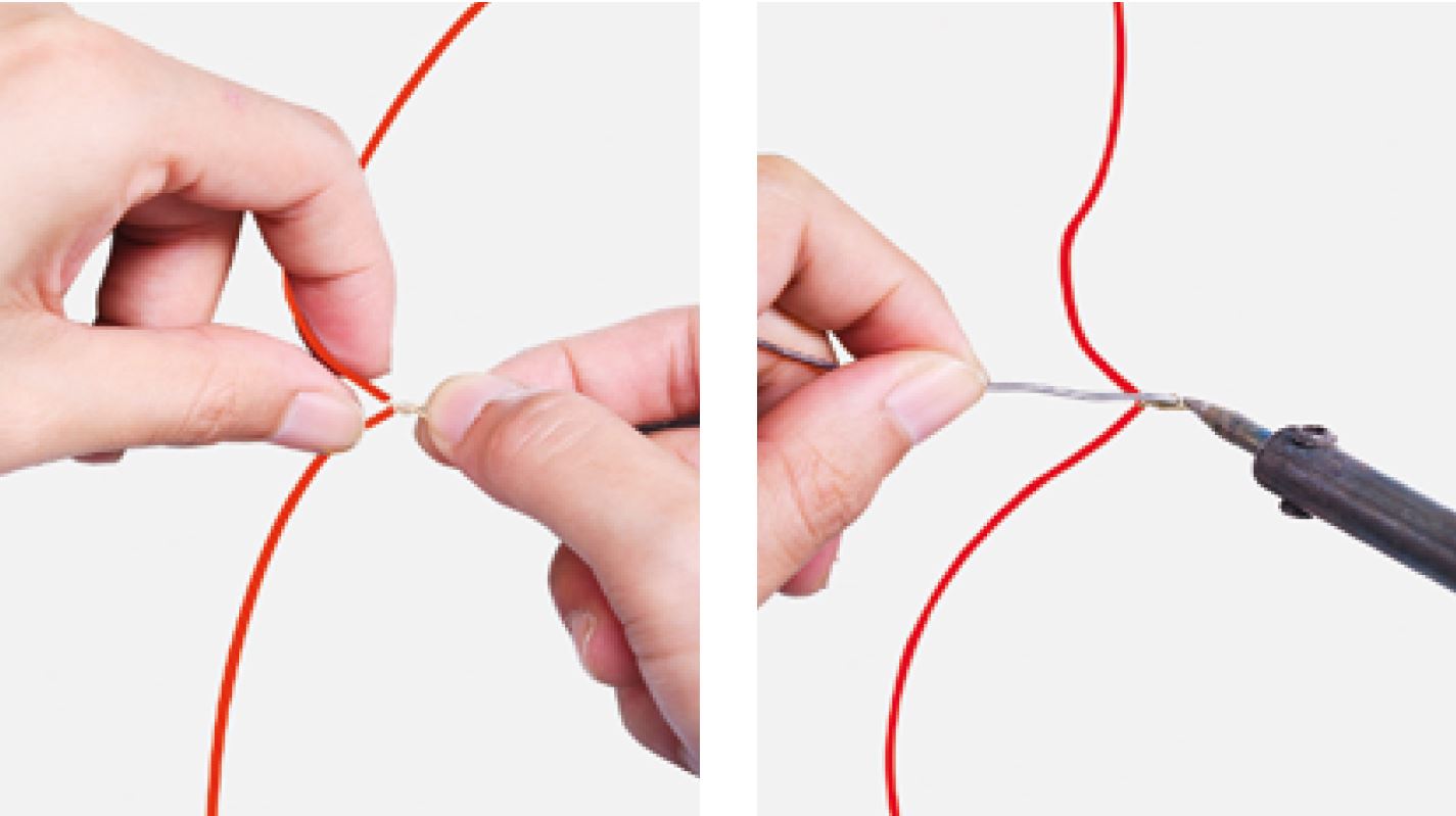
Peel off the sleeves.
Step 3
Check to ensure proper
wire order and reconnect
them.
Step 4
Tin soldering.
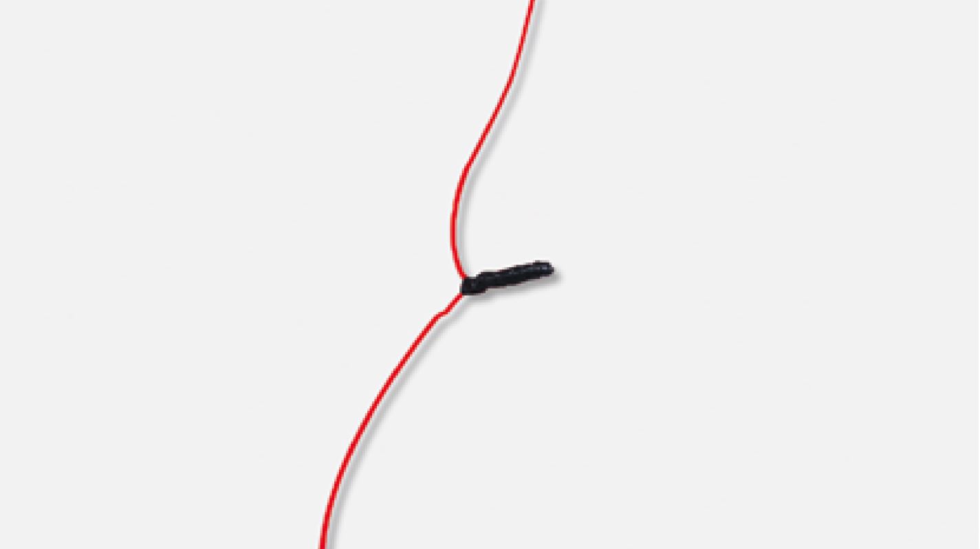
Step 5
Cover connecting point
with electrical tape.
CHECK AND TEST 4
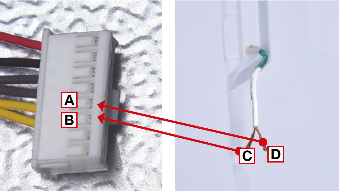
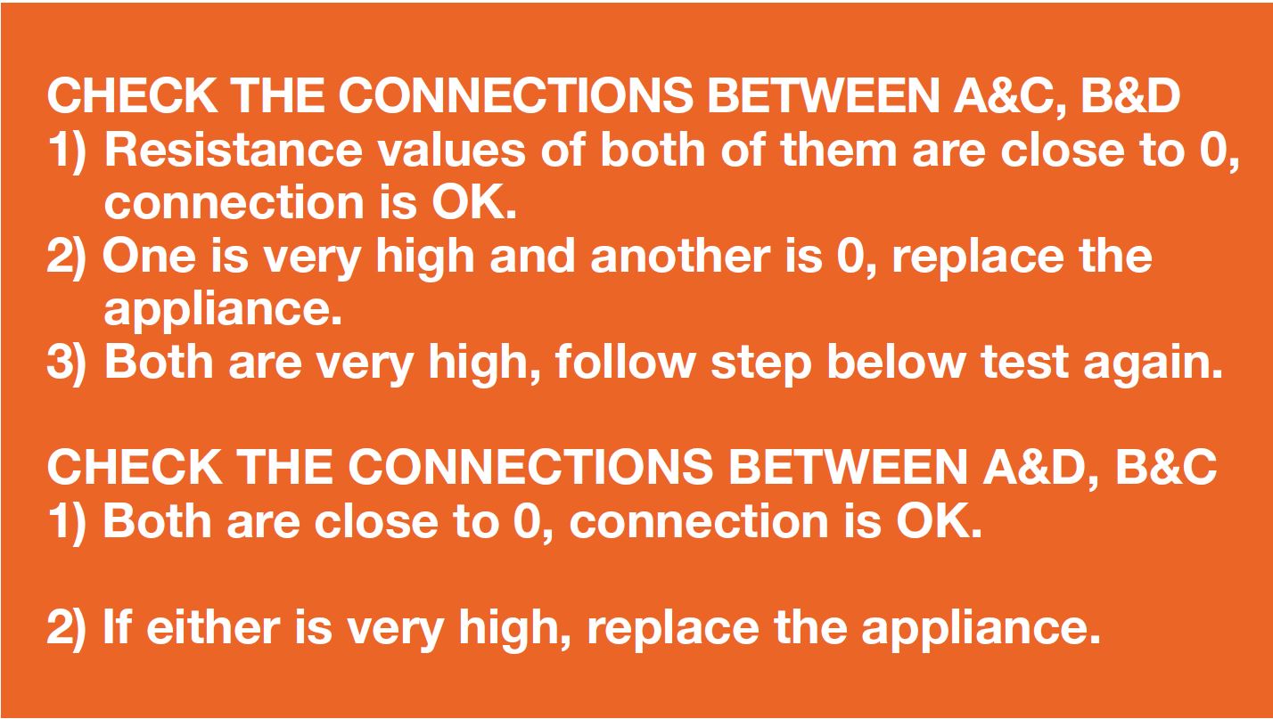
Step 1
Set multimeter to
resistance gear.
Step 2
Put one detector into
one end of wires in
PCB area, and another
detector into one end of
wires in fridge air duct
cover.

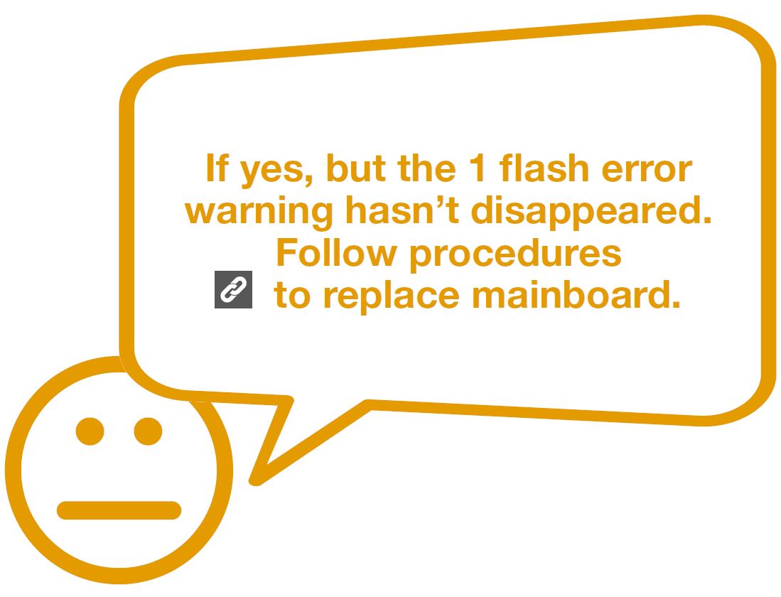
DIAGNOSISI 4


PROCEDURE 3
CHECK AND TEST 5


DIAGNOSIS 5


PROCEDURE 3

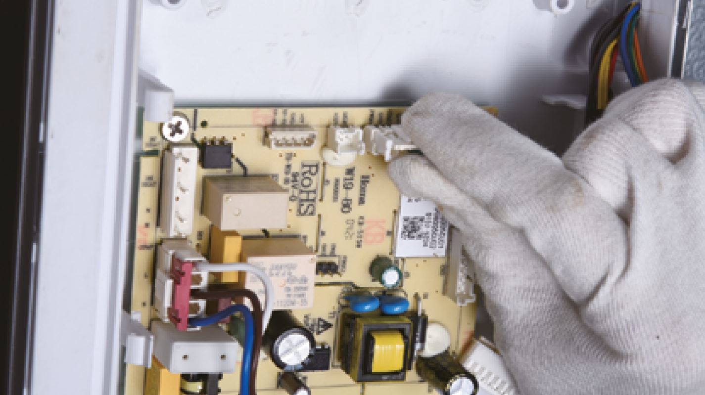
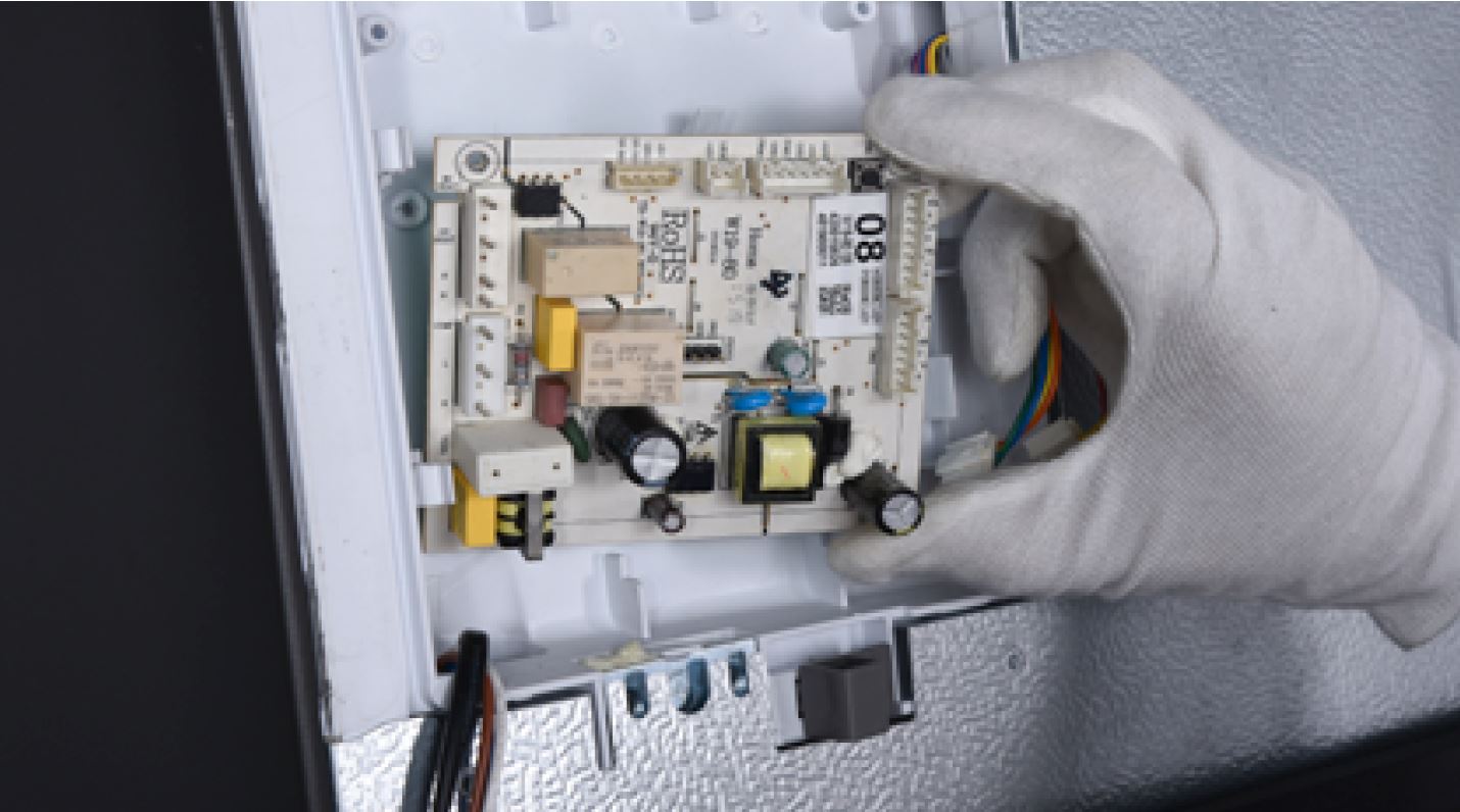
Step 1
Unscrew cover of
mainboard with a
Cross-head screwdriver.
Step 2
Disconnect terminals.
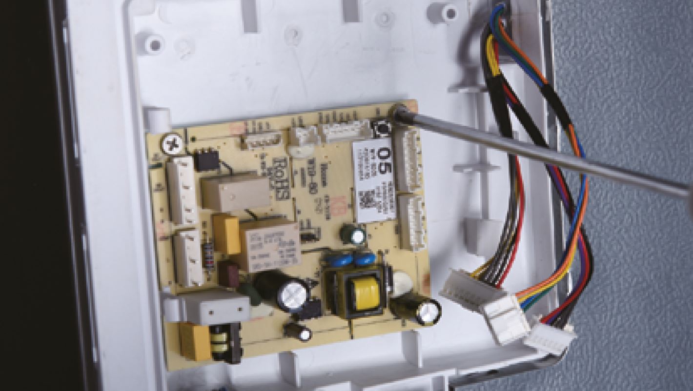
Step 3
Prize up the buckle and
disconnect the terminal.
Step 4
Unscrew the mainboard.
Step 5
Remove the mainboard.
Reverse steps above
to install a new
mainboard.

DIAGNOSIS 6


GO BACK TO COMPONENT LIST