CHECK AND TEST 1
Step 1
Unscrew cover ofmainboard with a
Cross-head screwdriver.

Step 2
Check if terminal in PCB
area is pushed to final
position.
If not, reinsert it to final
position.

Step 3
Set multimeter to
resistance gear.

Step 4
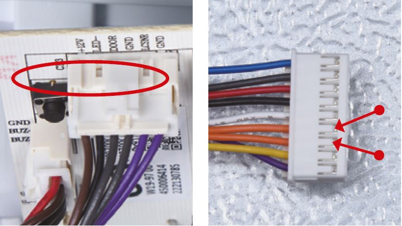
In PCB area, measure the
resistance of defrost temp.
sensor with a multimeter.
Step 5
Take note of value.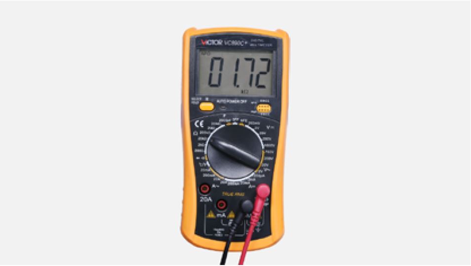
Step 6
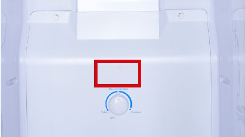
Measure the temperature
of freezer air duct, near the
defrost temp. sensor.
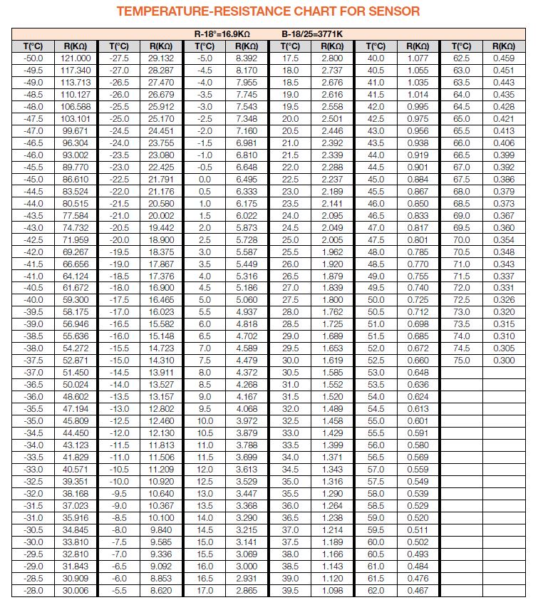
Use measured temperature
to find the standard
resistance value in
Temperature-Resistance
Chart for Sensor.

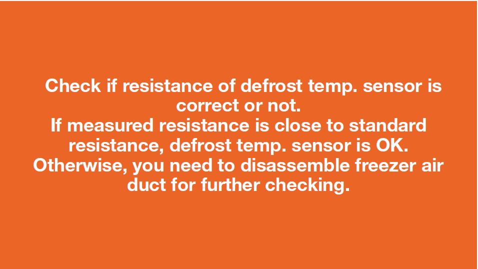
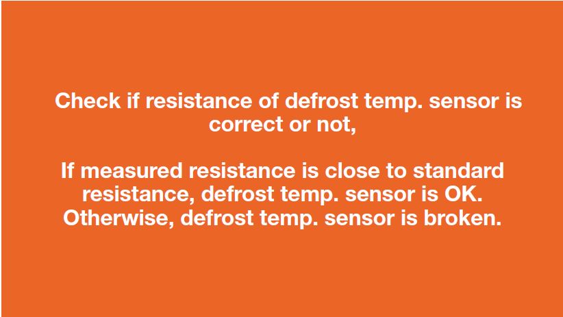
DIAGNOSIS 1

PROCEDURE 1
Step 1
Remove all shelves.
Step 2
Remove basket.
Step 3
Remove screw covers.
Step 4
Unscrew.
Step 5
Pull the buttom air duct
out.

Step 6
Disconnect the wires for
thermostat.
Step 7
Take bottom air duct
away.


CHECK AND TEST 2
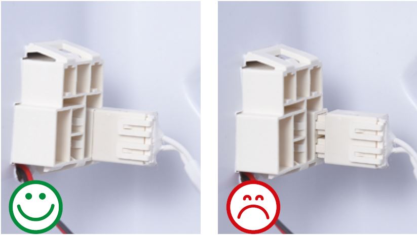
Check if the terminal
is inserted into final
position.
IF NOT, REINSERT
IT.
Step 2
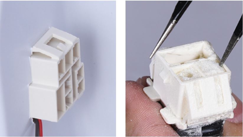
Check if the terminal is
stuffed with foam.
IF SO, USE TWEEZERS
TO SMASH IT AND
REMOVE.
Step 3
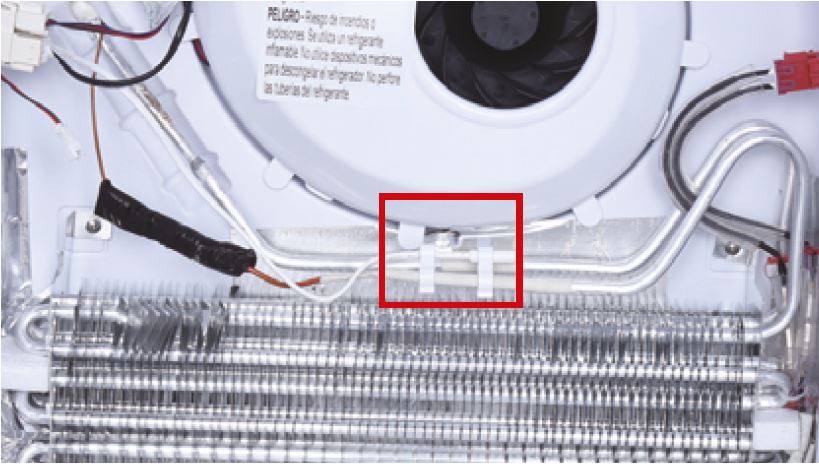
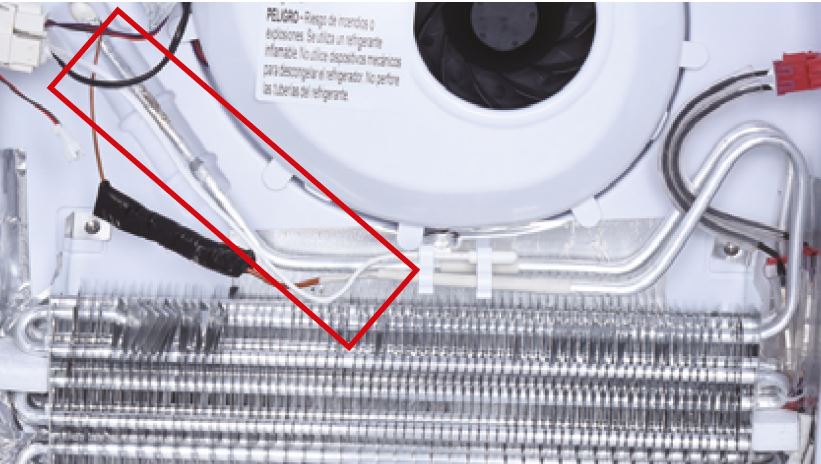
Check if sensor is
attached in proper
position, as shown in
picture.
If not, correct it.
Step 4
Check if wire of defrost
sensor is broken.
If yes, replace it with a
new one.
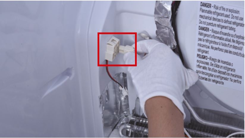
Step 5
Disconnect terminal of
defrost temp. sensor.
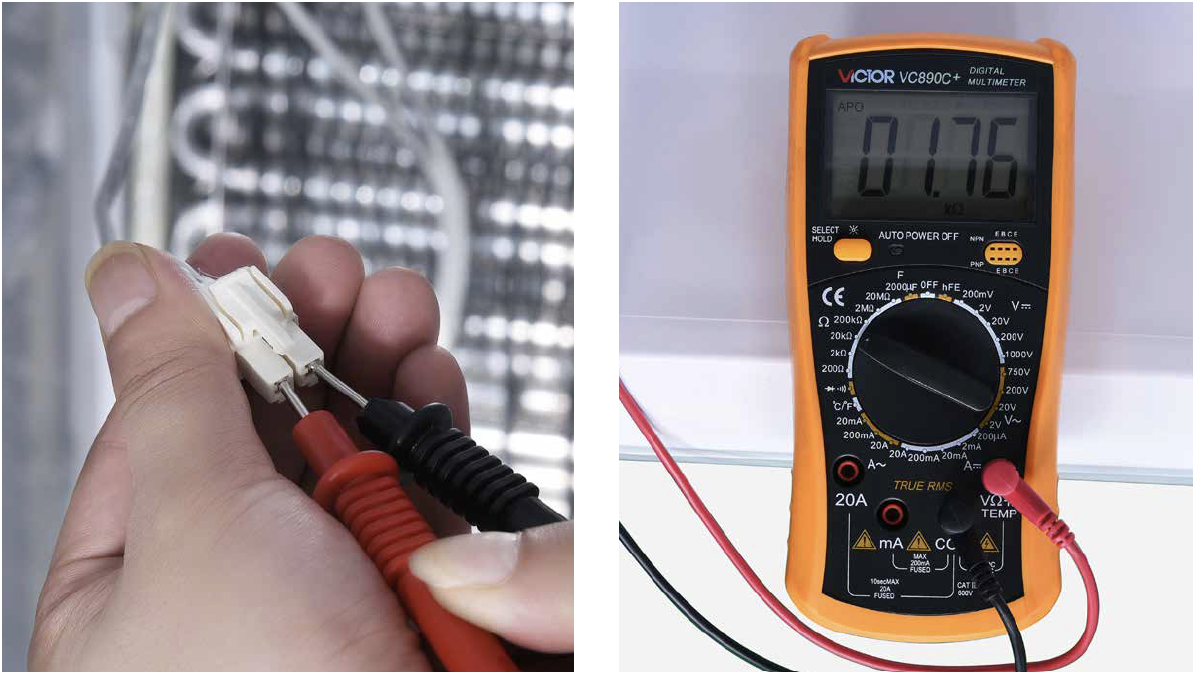
Step 6
Measure resistance ofdefrost temp. sensor
from terminal in freezer,
and take note of it.
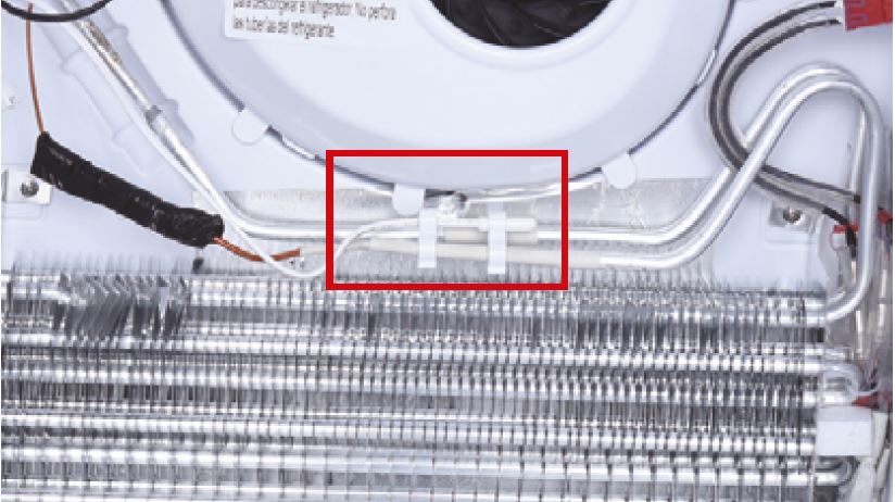
Step 7
Measure the temperature
of defrost temp. sensor.
Use measured
temperature to find the
standard resistance
value in Temperature-
Resistance Chart for
Sensor.

DIAGNOSIS 2


CHECK AND TEST 3
Step 1
Set multimeter toresistance gear.

Step 2
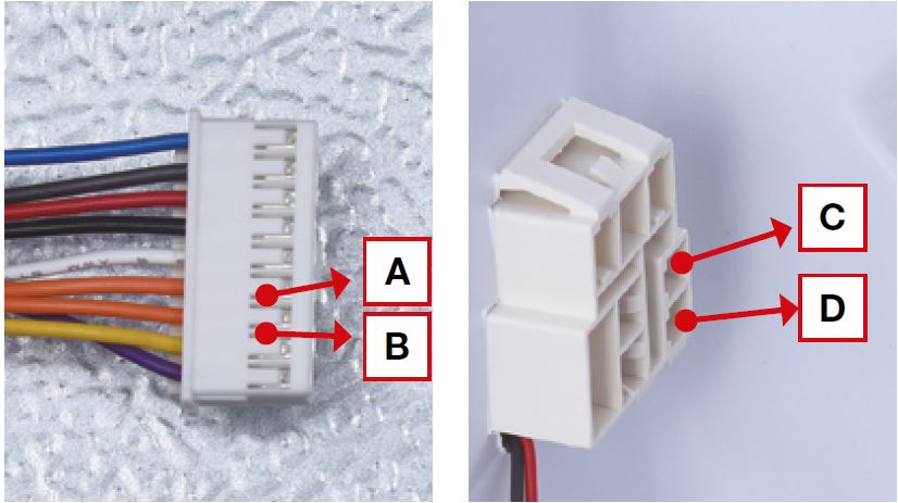
Put detector into one
end of wires in PCB area.
Put another detector into
end of wires behind air
duct.

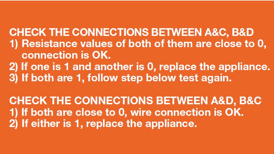
DIAGNOSIS
