


CHECK AND TEST 1
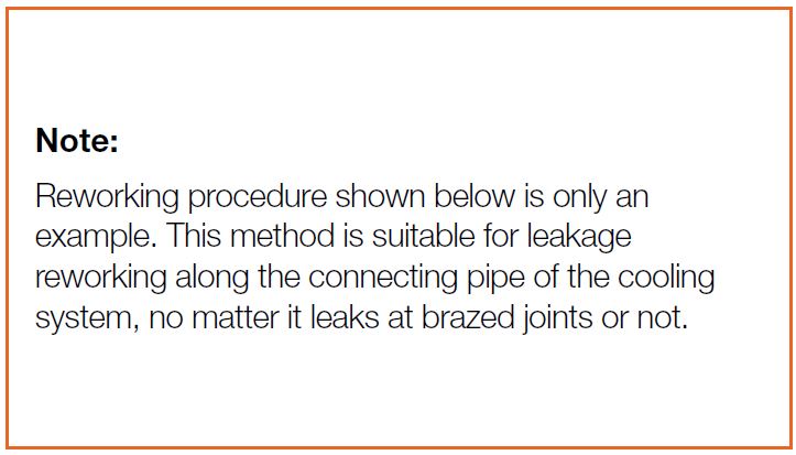
Note
Step 1
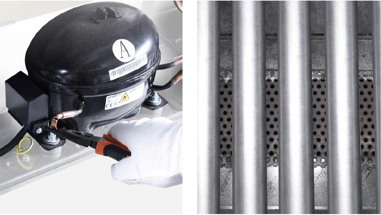
Discharge refrigerant:1) Use pliers to cut off charging tube.
2) Discharge all refrigerant toward the exhaust vent.
Step 2
Melt brazing material with flame and pull processing tube out using a pair of pliers.
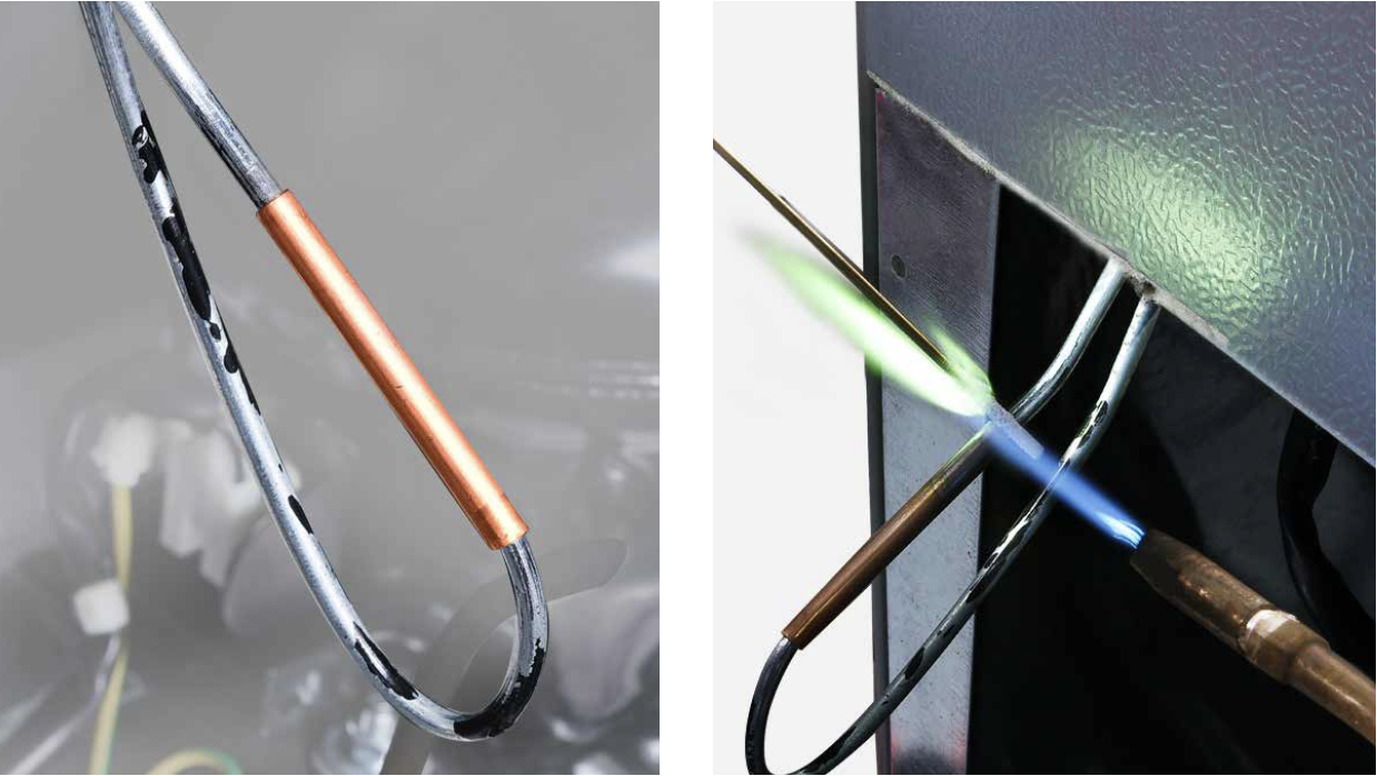
Step 3
Re-braze a copper tube
onto processing tube of
compressor.
To get more details on
brazing requirements,
please go to page 435

Note
Step 4
Install quick connector onto rebrazed pipe.
Step 5
Inject nitrogen of 1.57Mpa through quick connector into pipe.
Step 6
Test brazed joints in compressor niche for leaks with soapy water.
DIAGNOSIS 1


PROCEDURE 1
Step 1
Clean paint off of brazed joint.
Step 2
Cut off brazed joint with leakage.
Step 3
Use a bigger copper tube to connect 2 ends of brazed joint.Step 4
Braze the 2 ends.
Please get more details
of brazing requirements
on Annex page
Note
CHECK AND TEST 2
Step 1
Inject 1.57Mpa nitrogen through quick connector into pipe and apply soapy water to test for leaks again.
Step 2
Check gas leakage with soapy water again at all brazed joints in compressor niche.
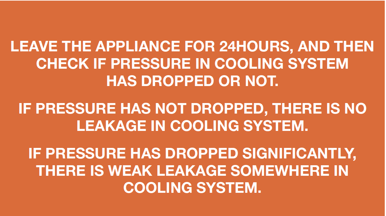
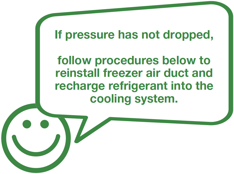
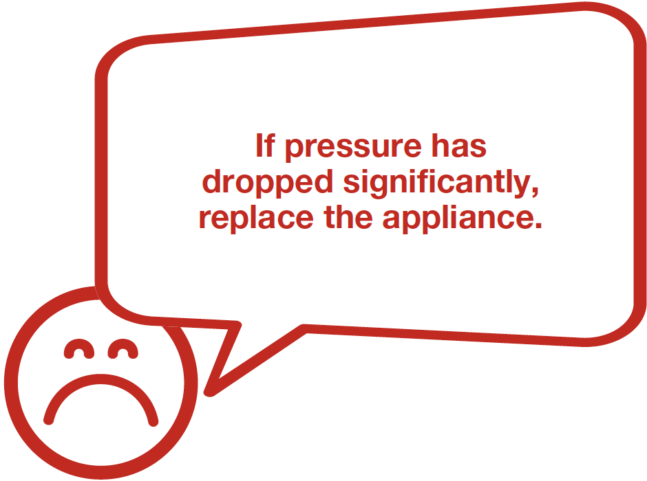
DIAGNOSIS 2

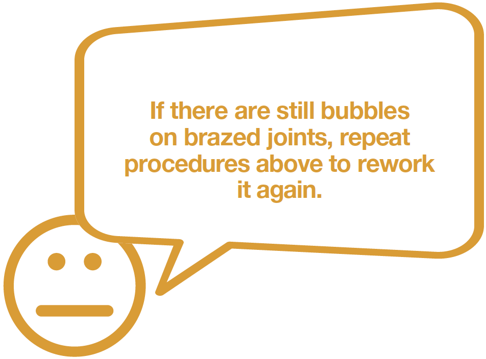
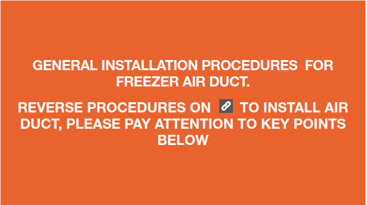
PROCEDURE 2
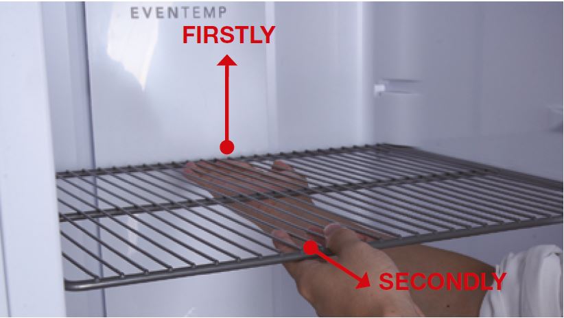
Step 1
Remove all shelves.
Step 2
Remove basket.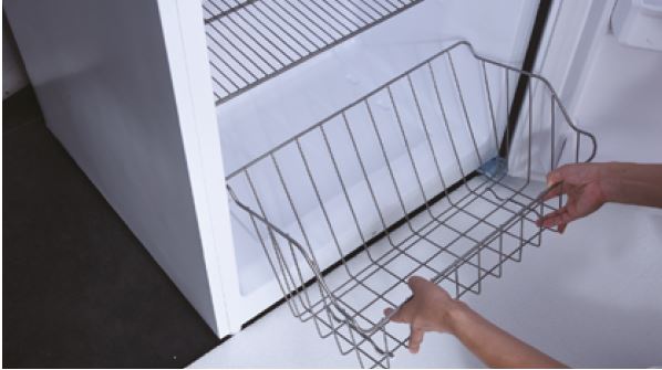
Step 3
Remove screw covers.
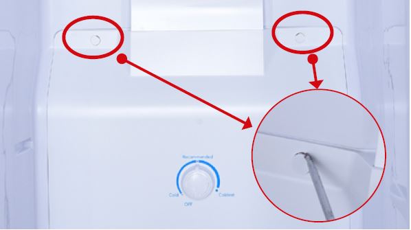
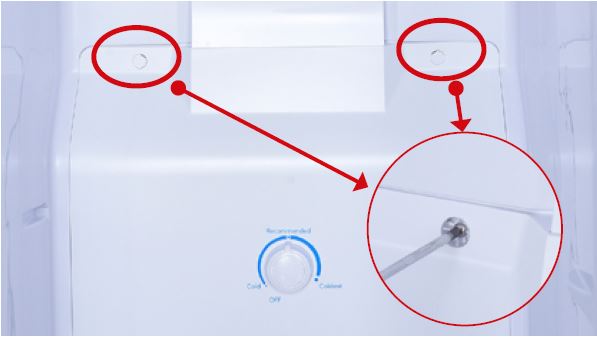
Step 4
Unscrew.
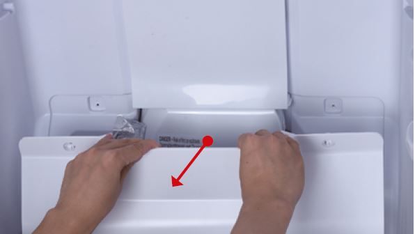
Step 5
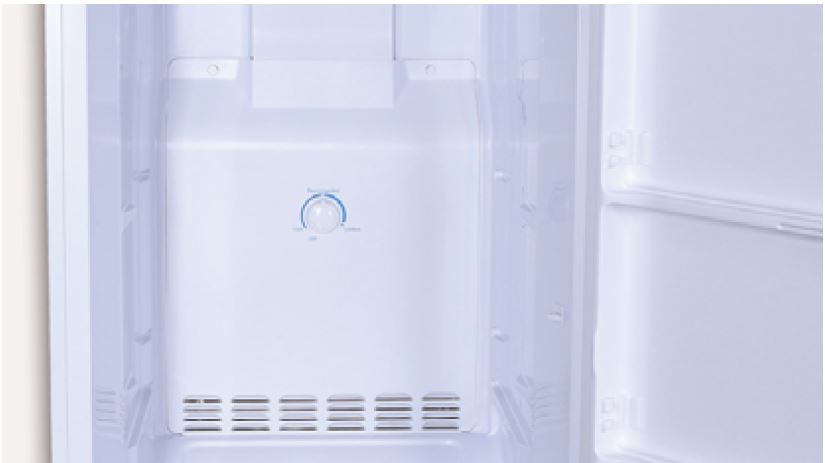
Pull the buttom air duct
out.
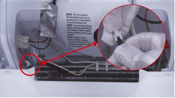
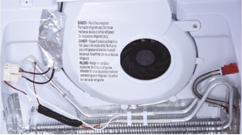
Step 6
Disconnect the wires for
thermostat.
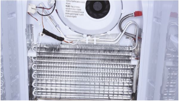
Step 7
Take bottom air duct
away.
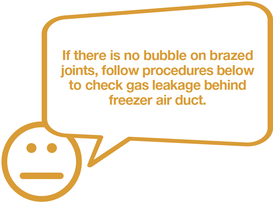
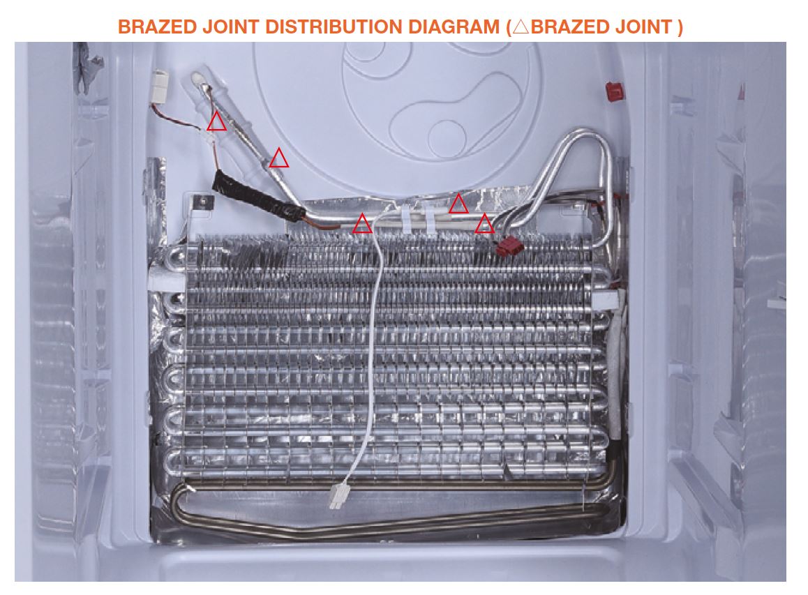
CHECK AND TEST 3
Step 1
Inject 1.57Mpa nitrogen through quick connector into pipe and check gas leakage behind freezer air duct.
DIAGNOSIS 3

PROCEDURE 3
Step 1
Clean paint off of brazed joint.
Step 2
Cut off brazed joint with leakage.
Step 3
Use a bigger copper tube to connect 2 ends of brazed joint.
Step 4
Braze the 2 ends.
Please get more details
of brazing requirements
on Annex page

Note
CHECK AND TEST 4
Step 1
Inject 1.57Mpa nitrogen through quick connector into pipe and check gas leakage behind freezer air duct.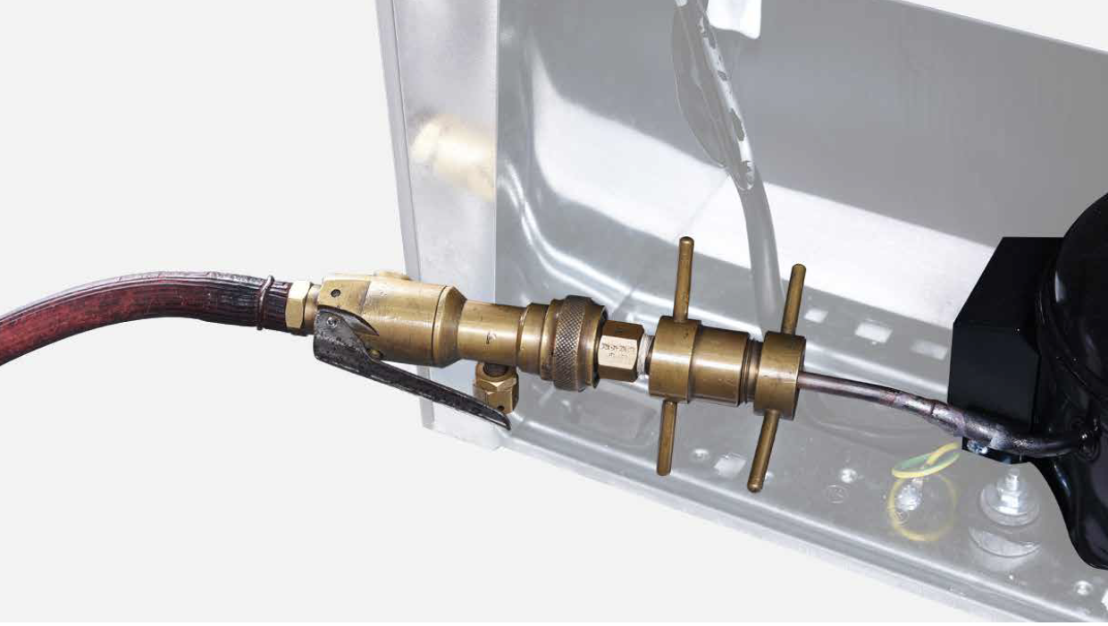
DIAGNOSIS 4

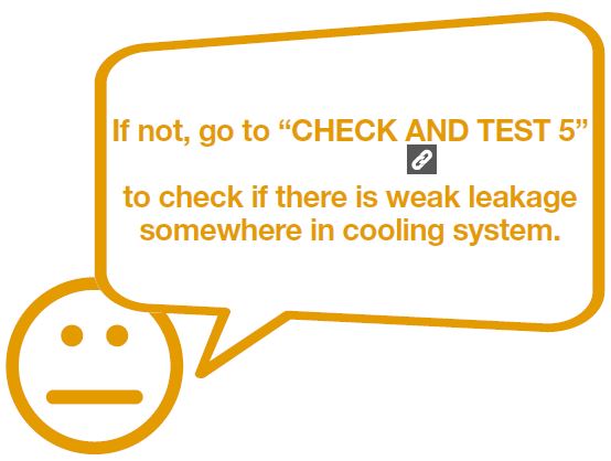
CHECK AND TEST 5
Step 1
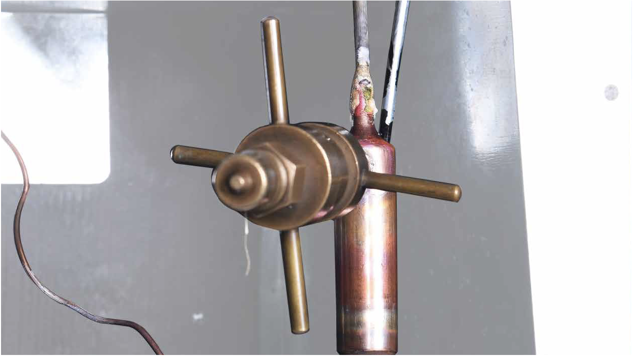
Braze a piezometer onto processing tube of compressor.
Step 2
Charge nitrogen of 1.57Mpa through quick connector into pipe.
Step 3
Perform leakage test
on brazing points and
piezometer to make sure
all connection points are
in good condition.

DIAGNOSIS 5
PROCEDURE 4
Tip 1
Make sure the sealing sponges are in good condition.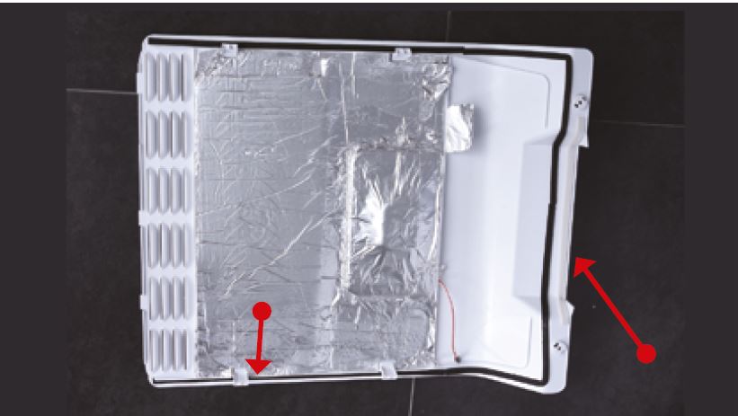
Tip 2
When reinstalling the air
duct, fasten the wires to
avoid crushing with air
duct.
Tip 3
Check to see if there is
a wide gap between air
duct and cabinet. If there
is, reinstall air duct.
PROCEDURE 5
Step 1
Clean paint off of brazed joint of drying filter.
Step 2
Cut off the brazed joint of drying filter.
Step 3
Cut off capillary and
remove the cut end by
shaking.

Step 4
Braze on a new drying-filter.
Step 5
Inject nitrogen (1.57Mpa) through quick connector into pipe for at least 3 min to blow remaining refrigerant away.
Step 6
Add quick connector onto processing pipe of drying-filter.
Step 7
Do leakage test on brazed joints of drying-filter and processing pipe on compressor.
Step 8
Vacuum and recharge.
To get more details
on vacuuming and recharging
requirements,
please go to Annex page

Step 9
Block processing pipe twice by locking pliers.
Step 10
Leave locked pliers attached to second block and shake to cut off the remaining pipe.
Step 11
Braze the ends and remove the pliers.

CHECK AND TEST 6
DIAGNOSIS 6


GO BACK TO COMPONENT LIST