


CHECK AND TEST 1
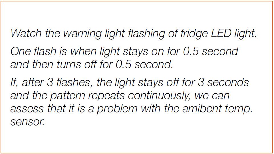
Step 1
Unscrew higne cover
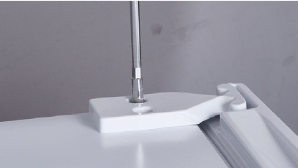
Step 2
Turn hinge cover over.
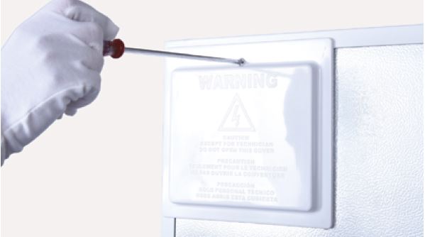
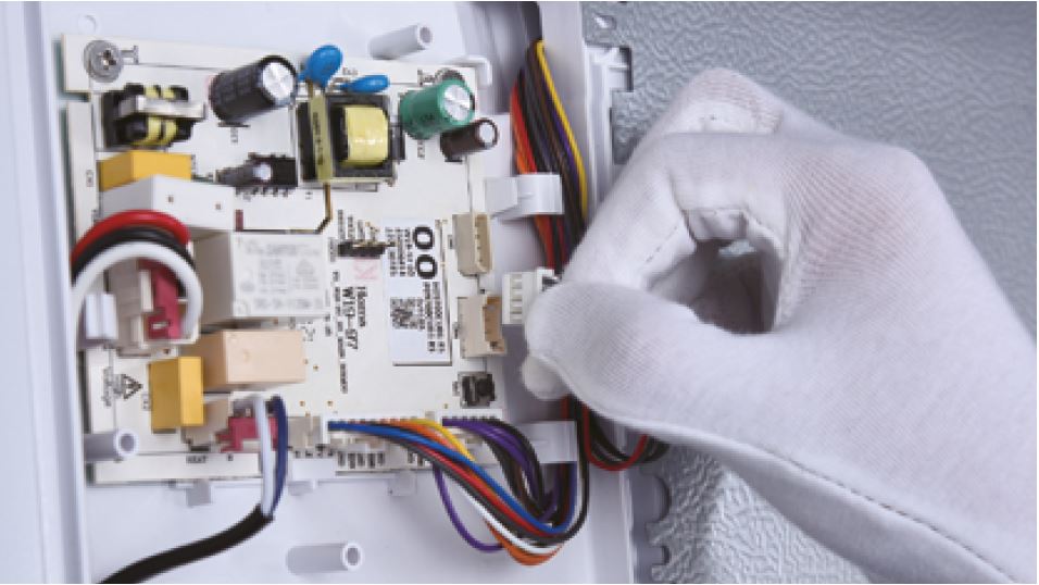
Step 3
Unscrew cover of
mainboard with a
Cross-head screwdriver.
Step 4
In PCB area, measure the
resistance of ambient temp.
sensor with a multimeter.
Step 5
Measure the temperature
of ambient temp. sensor.
Use measured
temperature to find the
standard resistance
value in Temperature-
Resistance Chart for
Sensor.
DIAGNOSIS 1


PROCEDURE 1
Step 1
Unscrew cover of
mainboard with a
Cross-head screwdriver.

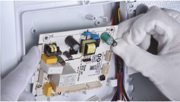
Step 2
Disconnect terminals.
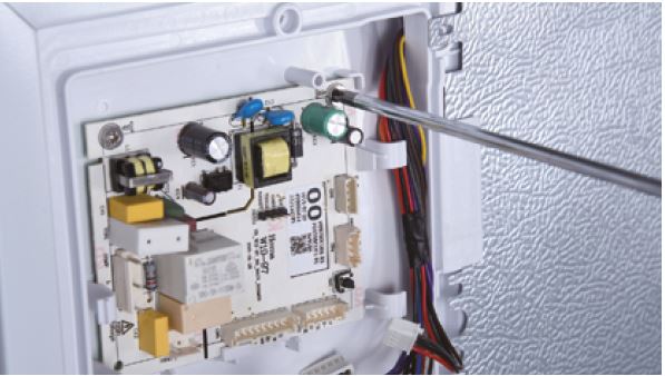
Step 3
Unscrew the mainboard.Step 4
Prize off the buckle to
remove mainboard.
Reverse steps above
to install a new
mainboard.

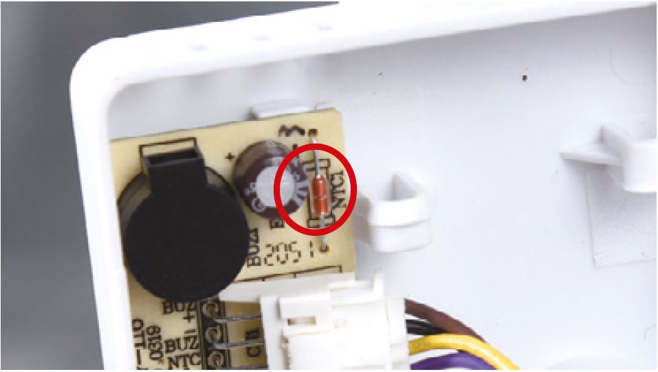
CHECK AND TEST 2
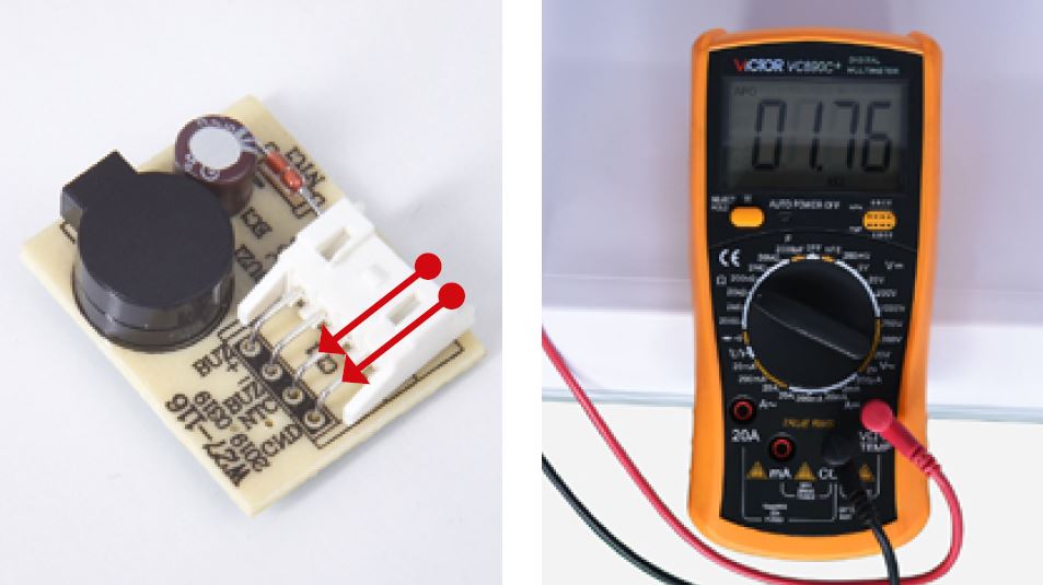
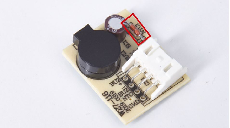
Step 1
Measure resistance of
ambient temp. sensor
from buzzer PCB.
Step 2
Measure the temperature
of ambient temp. sensor.
Use measured
temperature to find the
standard resistance
value in Temperature-
Resistance Chart for
Sensor.
DIAGNOSIS 1

PROCEDURE 2
Step 1
Unscrew hinge cover
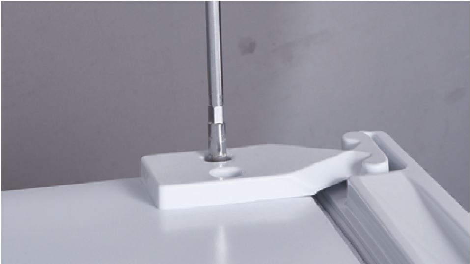
Step 2
Turn hinge cover over.Step 3
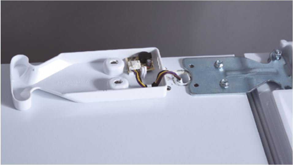
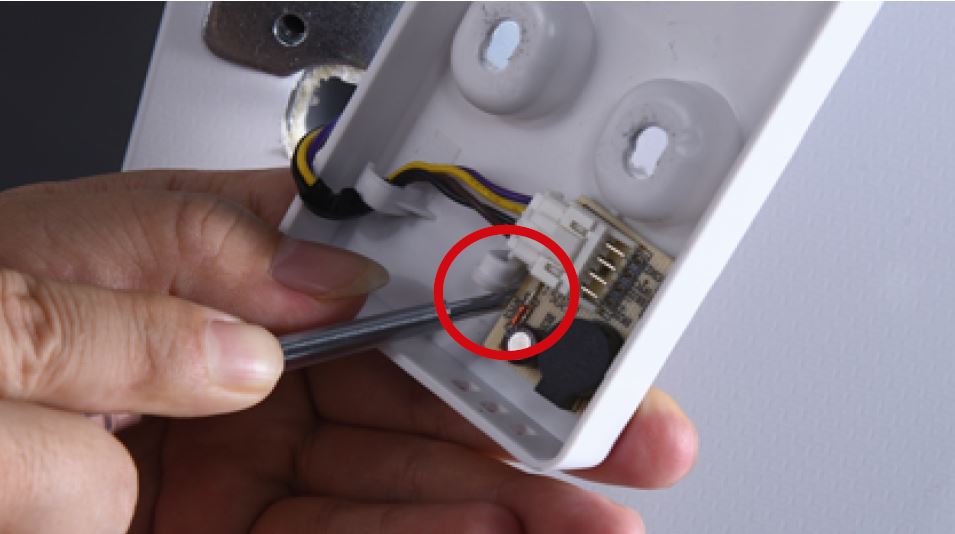
Use screw driver to push
the buckle inward and
prize the PCB board out.
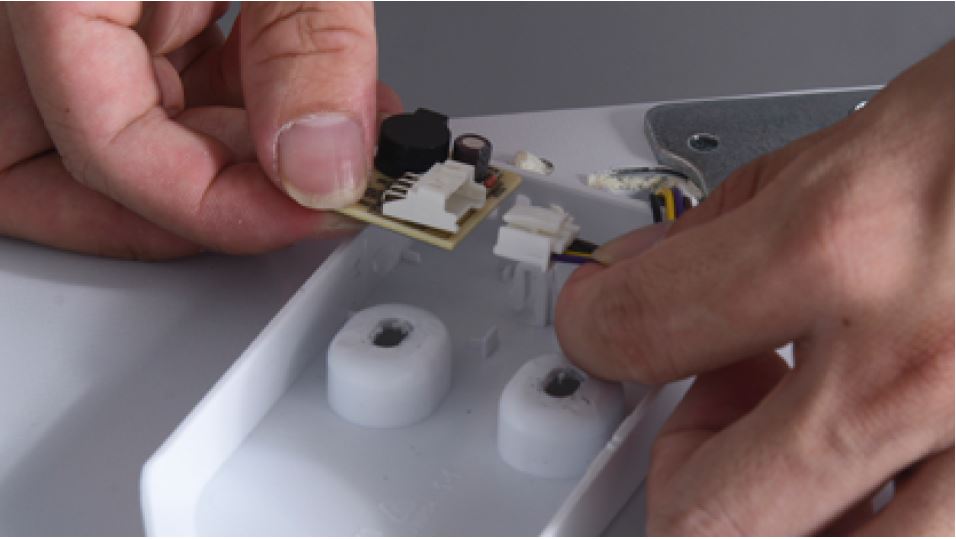
Step 4
Disconnect the terminal.
Reverse steps above
to install a new buzzer
board.
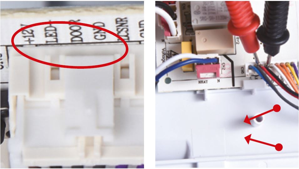
CHECK AND TEST 3
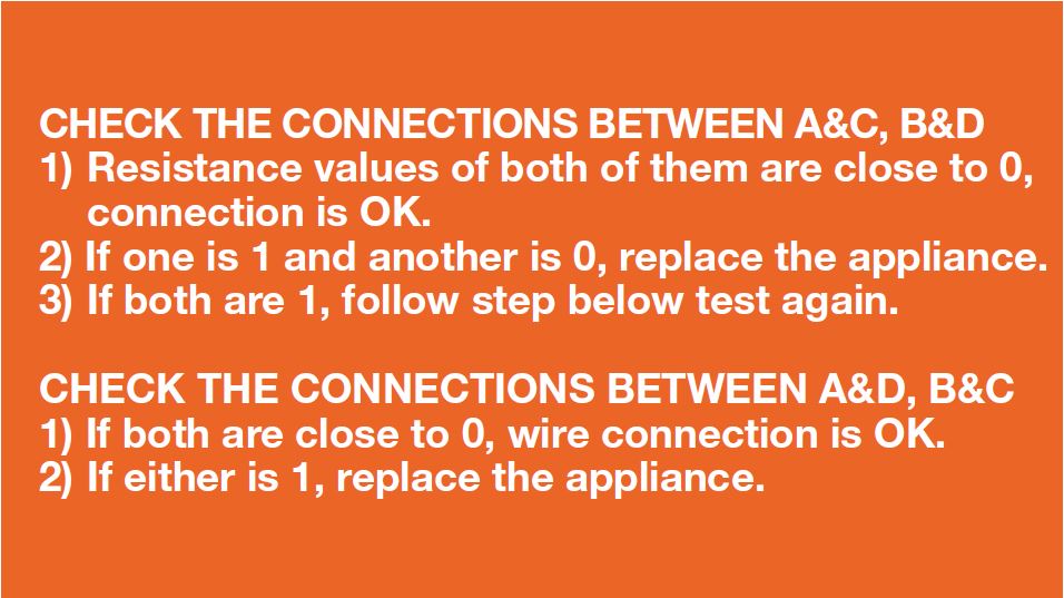
Step 1
Set multimeter to
resistance gear.
Step 2
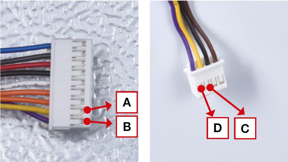
Put detector into one
end of wires in PCB area.
Put another detector into
end of wires behind air
duct.


DIAGNOSIS 3


GO BACK TO COMPONENT LIST