


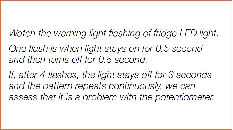
CHECK AND TEST 1
Note
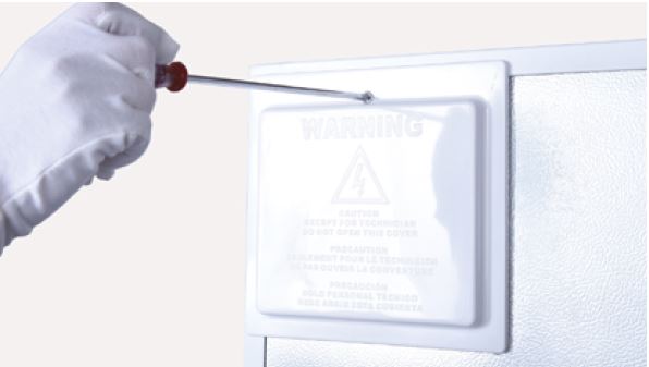
Step 1
Unscrew cover of
mainboard with a
Cross-head screwdriver.
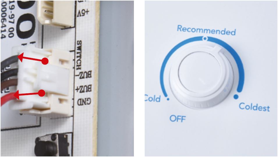
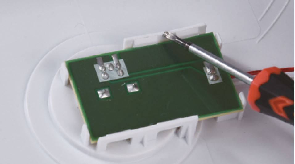
Step 2
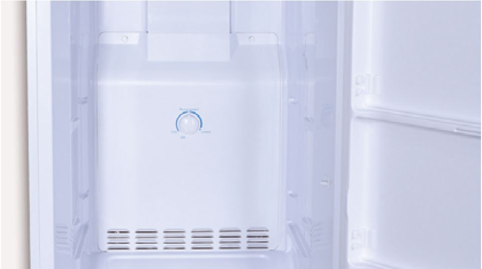
Test resistance of
potentiometer from
“DOOR” and “GND”.
Step 3
Turn the knob from 0 to
max to test resistance of
potentiometer.

DIAGNOSIS 1

PROCEDURE 1
Step 1
Unscrew cover of
mainboard with a
Cross-head screwdriver.

Step 2
Disconnect terminals.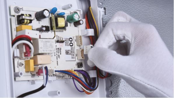
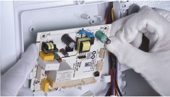
Step 3
Unscrew the mainboard.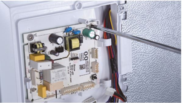
Step 4
Prize off the buckle to
remove mainboard.
Reverse steps above
to install a new
mainboard.

DIAGNOSIS 2


PROCEDURE 2
Note
Before replacing
potentiometer, you need
to disassemble air duct.
Step 1
Remove all shelves.
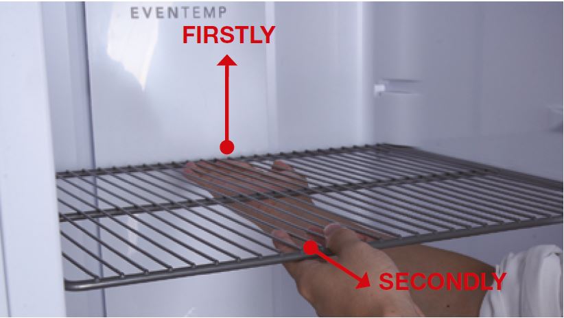
Step 2
Remove basket.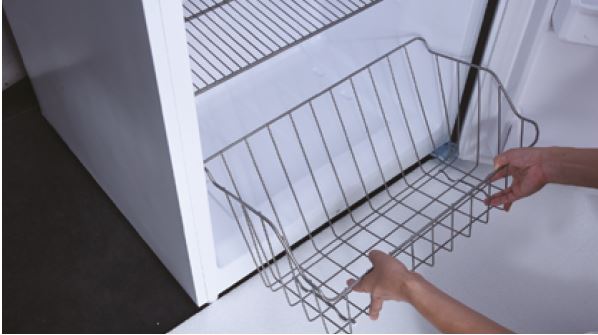
Step 3
Remove screw covers.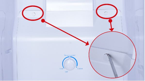
Step 4
Unscrew.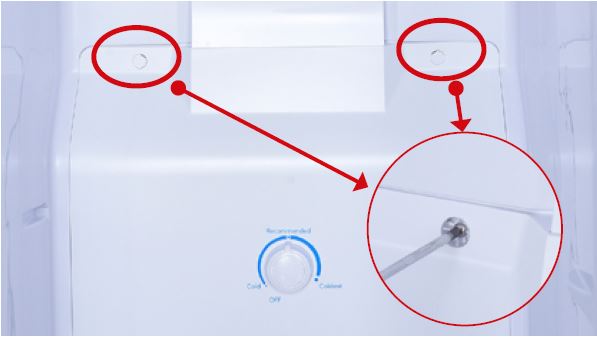
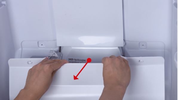
Step 5
Pull the buttom air duct
out.
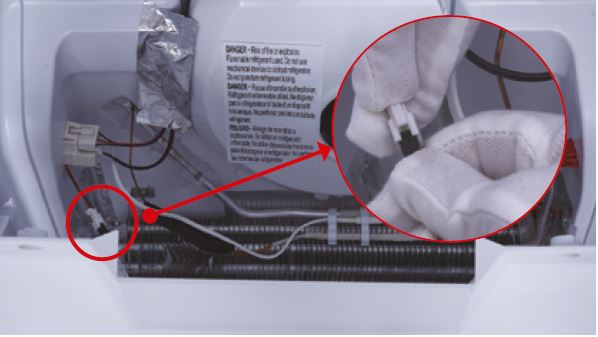
Step 6
Disconnect the wires for
thermostat.
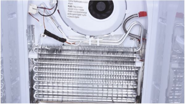
Step 7
Take bottom air duct
away.

PROCEDURE 3

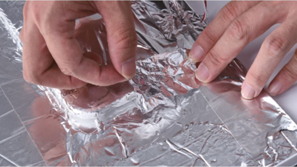
Step 1
Peel the tape
off.
Step 2
Take off the cover board.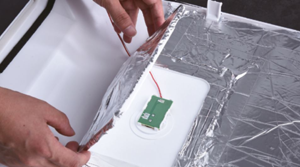
Step 3
Push the buckle behind
the PCB.
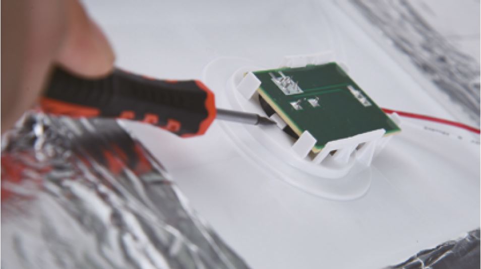
Step 4
Pull the knob out.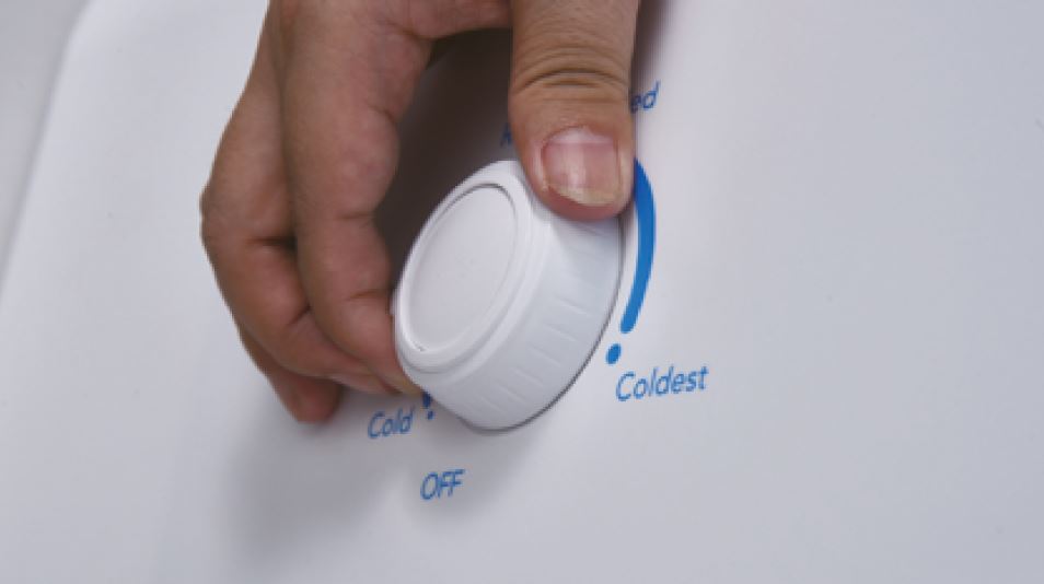
Step 5
Prize the potentiometer
out.
Step 6
Take off the cover board.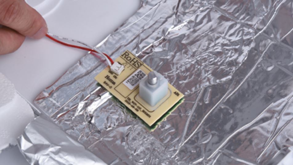
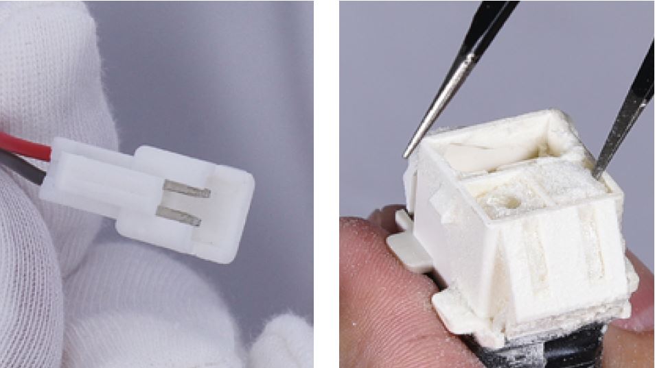
CHECK AND TEST 3
Step 1
Check if the terminal is
stuffed with foam.
IF SO, USE TWEEZERS
TO SMASH IT AND
REMOVE.
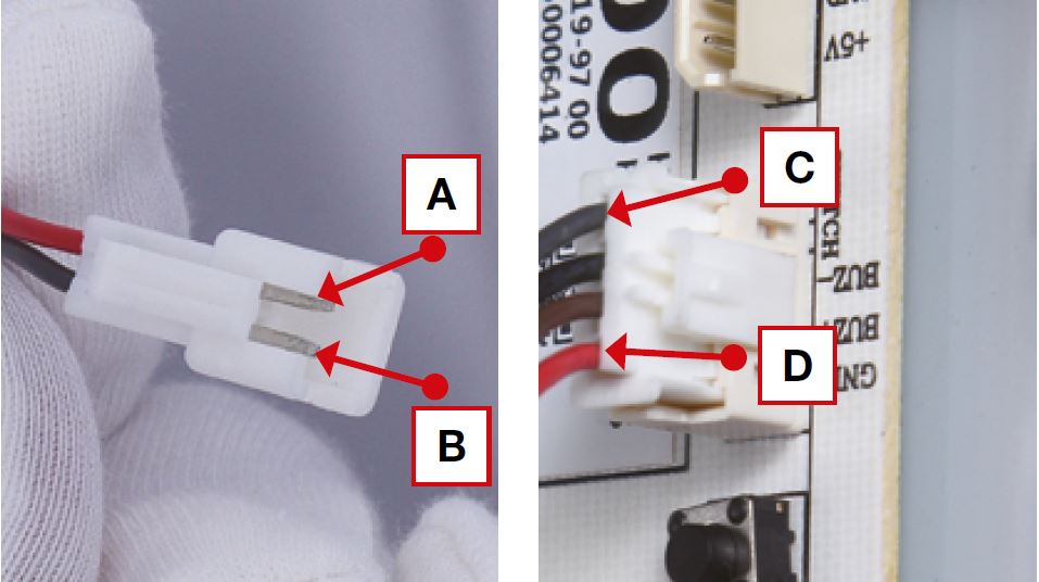
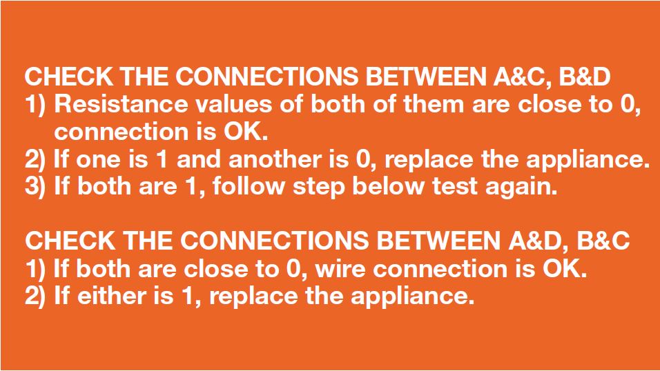
Step 2
Put detector into one
end of wires in PCB area.
Put another detector into
end of wires behind air
duct.

DIAGNOSIS 3

PROCEDURE 4
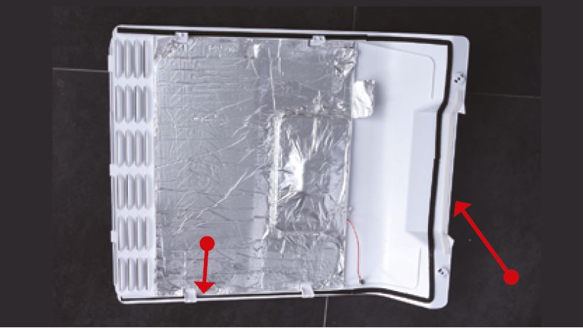
Tip 1
Make sure the sealing
sponges are in good
condition.
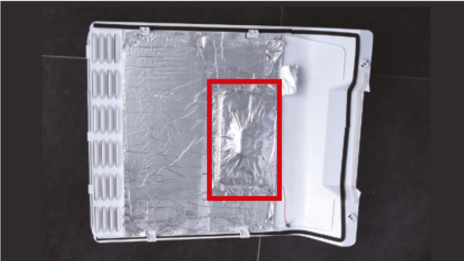
Tip 2
make sure the part in red
box is sealed well with
tape.
Tip 3
When reinstalling the air
duct, fasten the wires to
avoid crushing with air
duct.
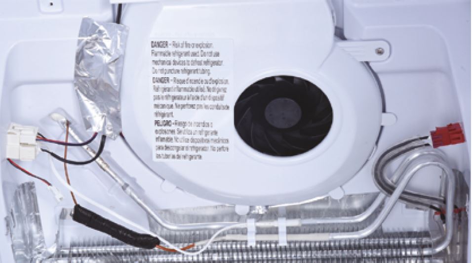
Tip 4
Check to see if there is
a wide gap between air
duct and cabinet. If there
is, reinstall air duct.

GO BACK TO COMPONENT LIST