


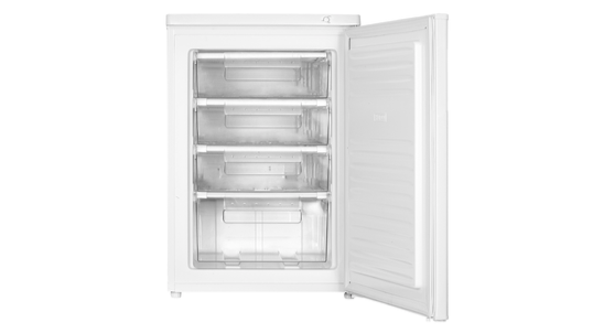
CASE 1:
TEMP. SETTING KNOB ON TOP COVER
CHECK AND TEST 1
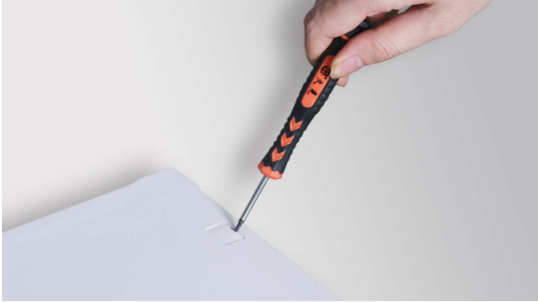
Step 1
Remove the screw cover.
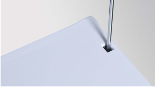
Step 2
Unscrew.
Step 3
Push the top cover forward.
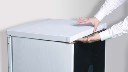
Step 4
Take away the top cover.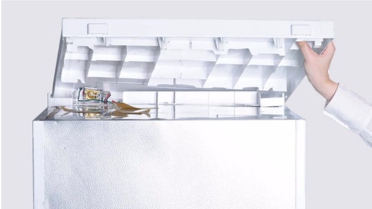
Step 5
Disconnect terminals for thermostat.
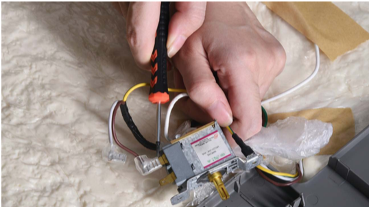
Step 6
Set thermostat gear between MIN and MAX (do not at MIN or MAX position), and measure resistance between terminal C and terminal H.
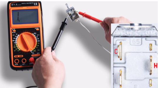

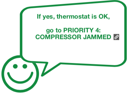
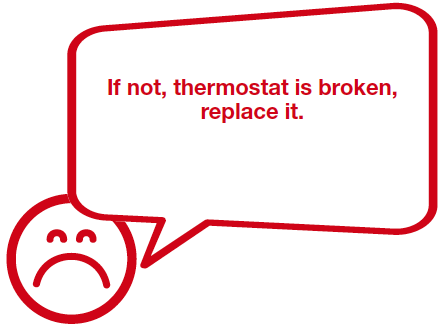
DIAGNOSIS 1


CASE 2:
TEMP. SETTING KNOB ON THE FOREHEAD OF CABINET
CHECK AND TEST 1
Step 1
Unscrew.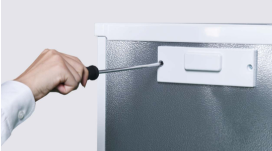
Step 2
Remove the thermostat cover.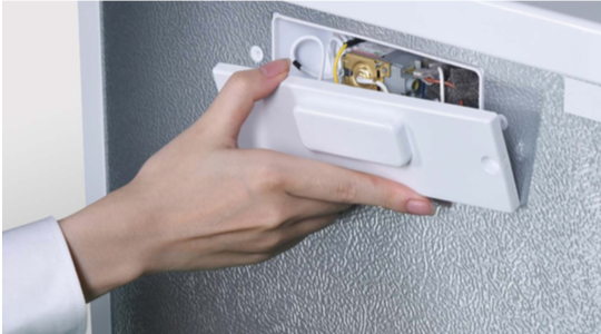
Step 3
Disconnect terminals for thermostat.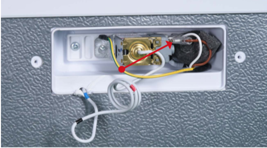
Step 4
Set thermostat gear between MIN and MAX (do not at MIN or MAX position), and measure resistance between terminal C and terminal H.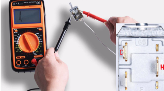
DIAGNOSIS 1

CASE 3:
TEMP. SETTING KNOB ON COMPRESSOR NICHE
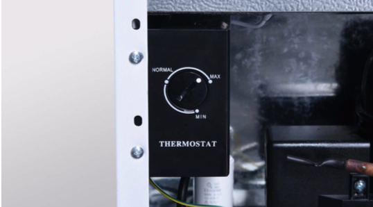
CHECK AND TEST 1
Step 1
Unscrew thermostat box.
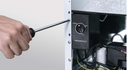
Step 2
Remove thermostat box.

Step 3
Disconnect terminals for thermostat.
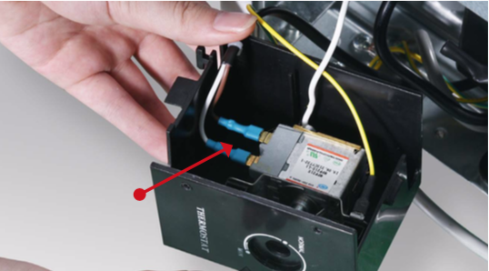
Step 4
Set thermostat gear between MIN and MAX (do not at MIN or MAX position), and measure resistance between terminal C and terminal H.
DIAGNOSIS 1


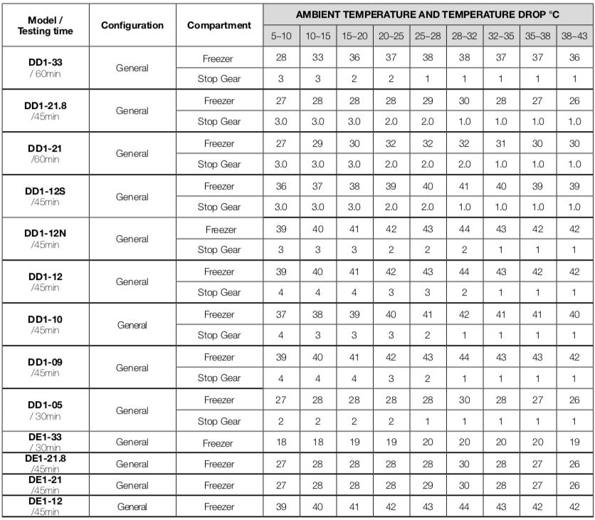
CHECK AND TEST 2
Performance Testing Procedures and Assessment Criteria.
1. Sensor position: Freezer: geometric center of freezer compartment.
2. Test time: 30min to 60min.
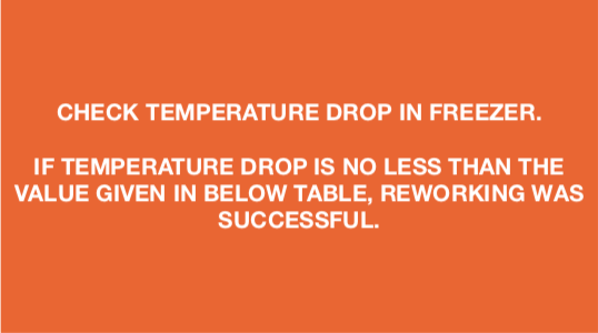
3. Stop Gear: compressor-stopping gear must be above the gear listed on the table.
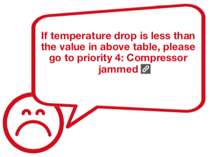
4. Temperature drop must be no less than the value on the table.
DIAGNOSIS 1


GO BACK TO COMPONENT LIST