

PROCEDURE 1

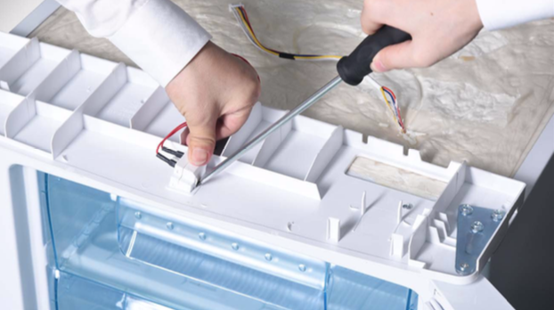
Step 1
Insert slotted screw driver into edge of switch and press the buckle on right side.
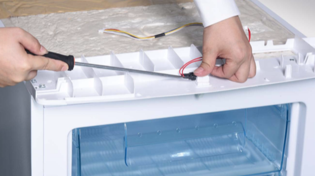
Step 2
Prize buckle from left side.
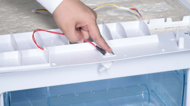
Step 3
Lever switch out of buckle.
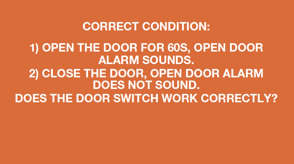
CHECK AND TEST 1
Step 4
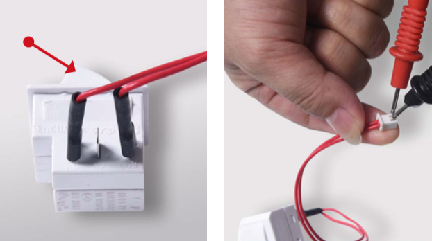
Check the connection of switch.
Use multimeter to measure the resistance value when switch button is in a free status.
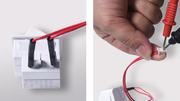
Step 5
Measure the resistance value again when switch button is pressed down.

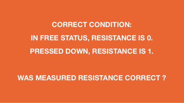
DIAGNOSIS 1


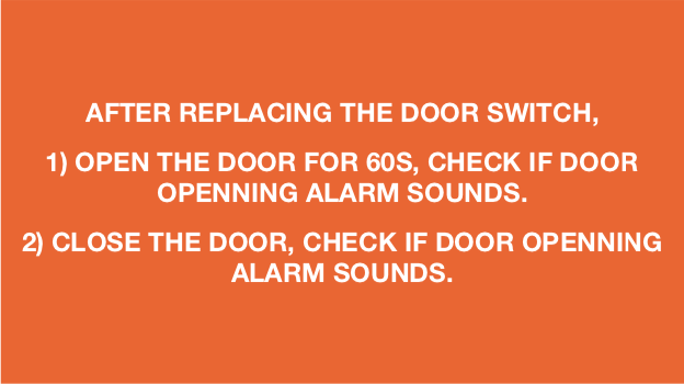
CHECK AND TEST 2
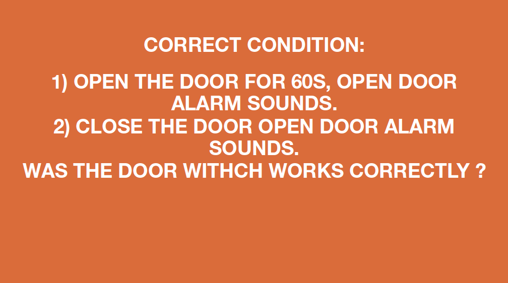
DIAGNOSIS 2


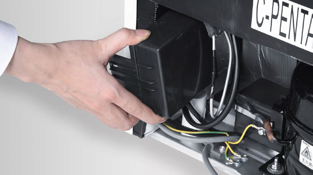
PROCEDURE 2

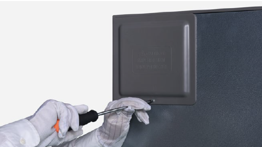
Step 1
Unscrew the cover ofmainboard.

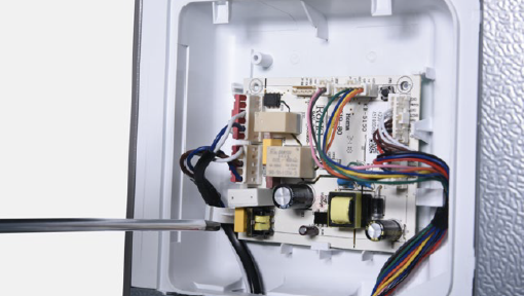
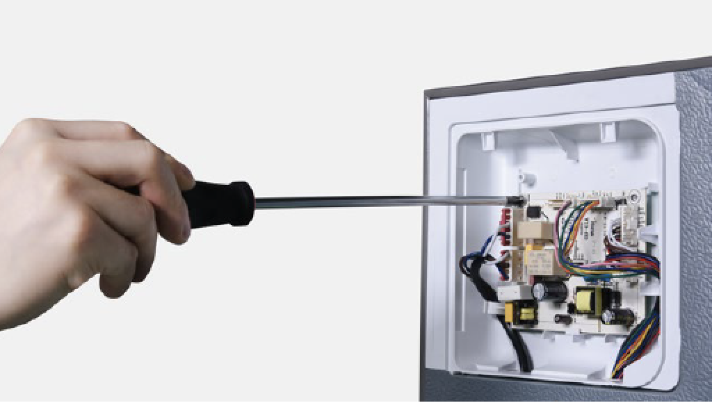
Step 2
Remove the mainboardbox.
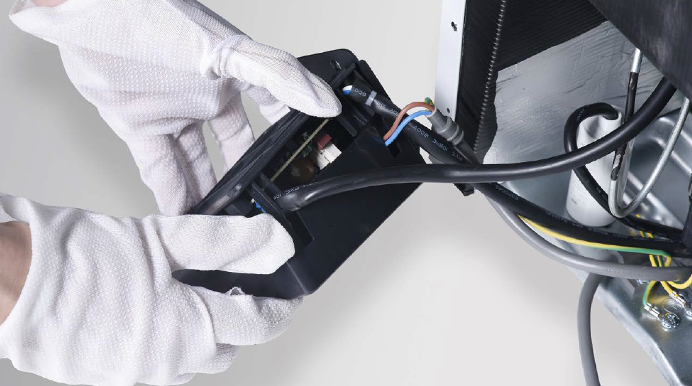
Step 3
Separate the mainboardbox.
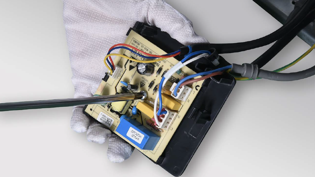
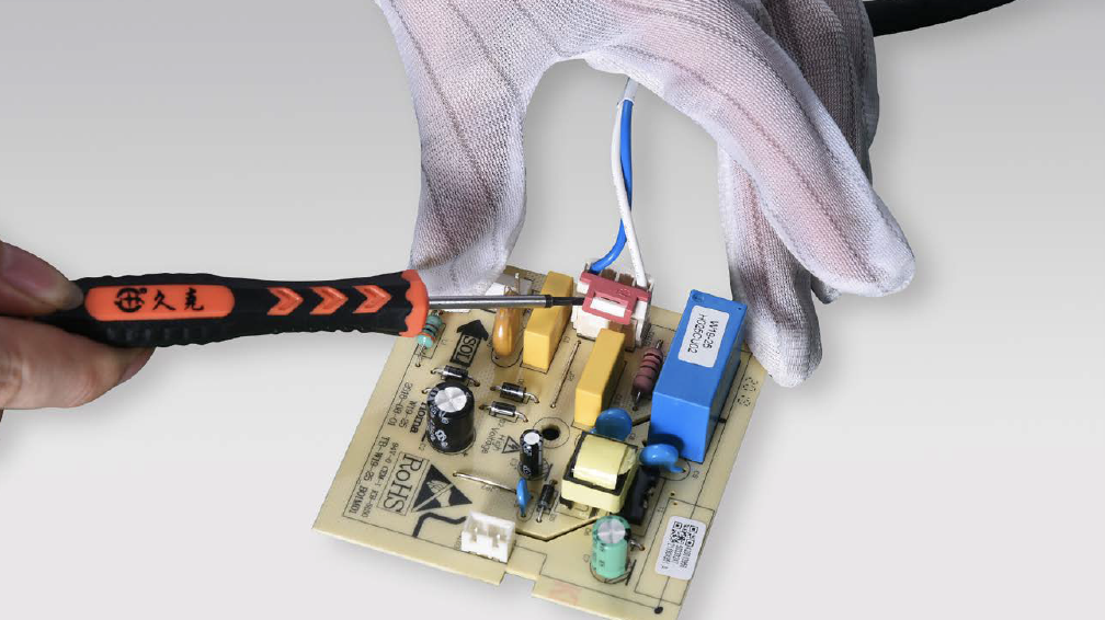
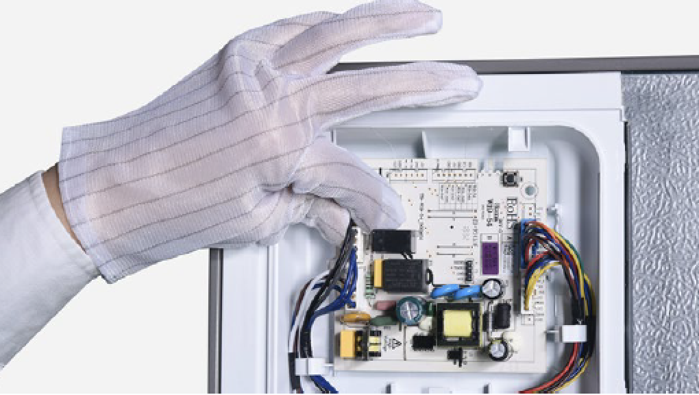
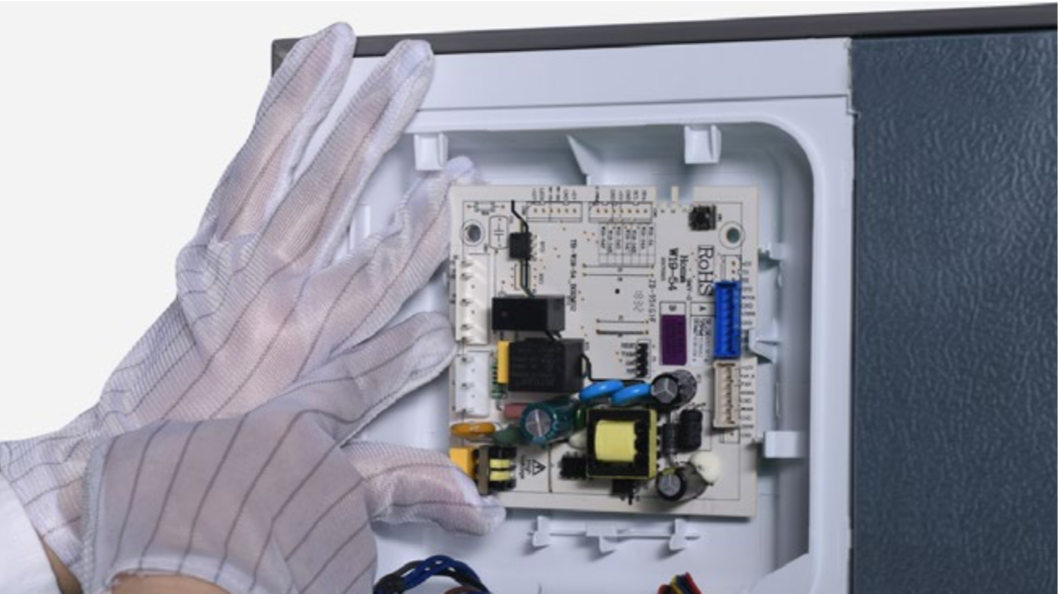
Step 4
Unsecrew and removePCB from the box.
Step 5
Prize off the buckle anddisconnect the terminal.

PROCEDURE 3

PROCEDURE 4

Step 1
Lever off screw cover.
Step 2
Unscrew.
Step 3
Push the top cover
forward.
Step 4
Take away the top cover.
Step 5
Disconnect the terminal
of display PCB.
Step 6
Unscrew and remove thedisplay PCB.

PROCEDURE 5
CHECK AND TEST 3
DIAGNOSIS 2


GO BACK TO FAULT LIST RELIABILITY