


PROCEDURE 1

Step 1
Unscrew bottomattachment.

Step 2
Unscrew topattachment.
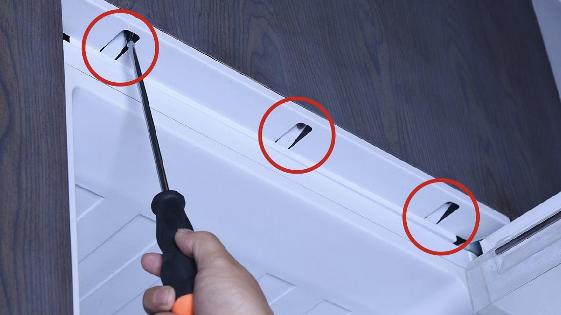
Step 3
Remove the plasticcover.
Step 4
Unscrew central
attachment on left and
right side.
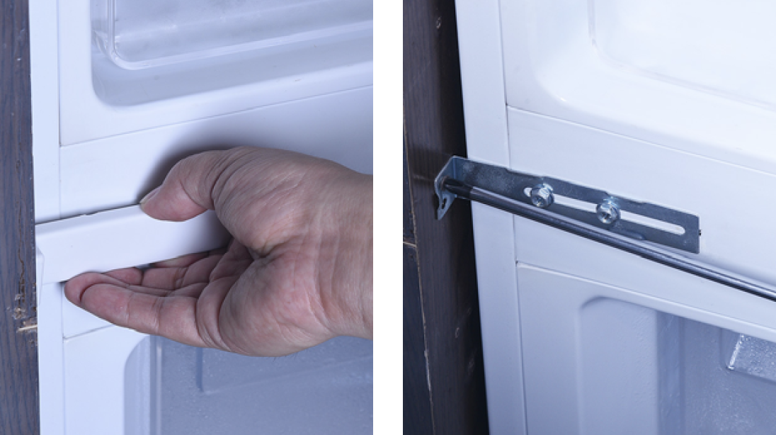
Step 5
Unscrew the plasticguider.

Step 6
Hold cabinet and pullappliance out.
Note:
Reverse procedures
above to install the
appliance.

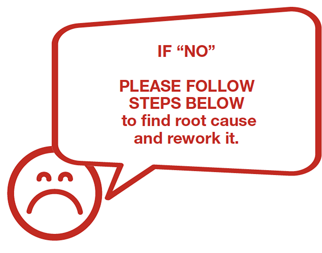
Note

CHECK AND TEST 2
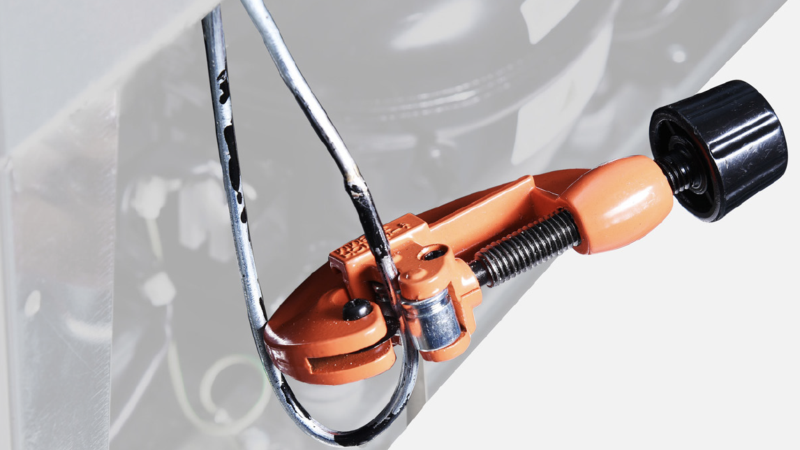
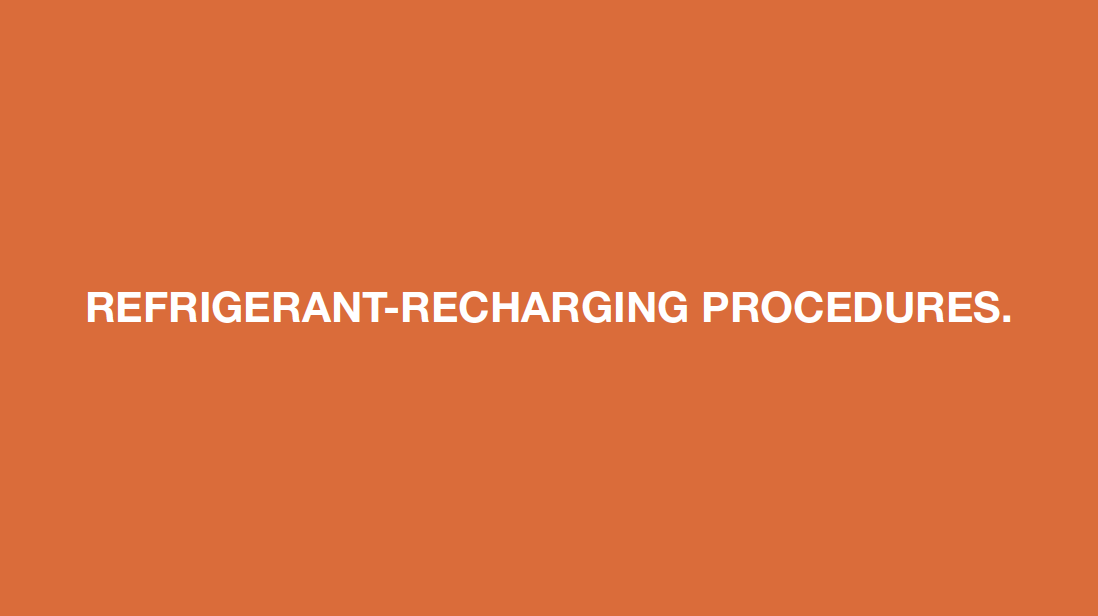
Step 1
Discharge refrigerant.Cut off the charging
tube with pliers.

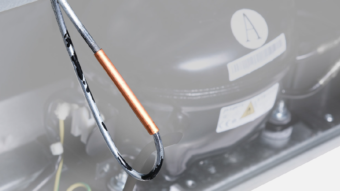
Step 2
Discharge all refrigeranttoward the exhaust vent.

Step 3
Melt brazing material with flame and pull out processing tube using a pair of pliers.
Step 4
Re-braze a copper tube onto compressor processing tube.Click below link to get more details for brazing requirements, go to Annex B1

NOTE
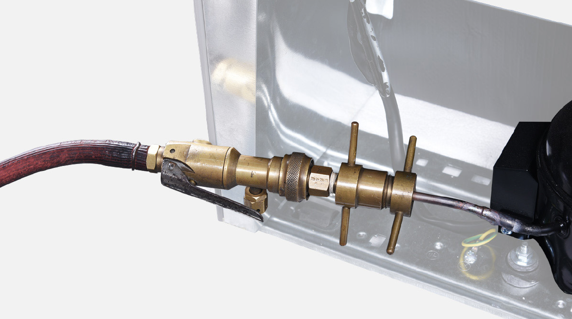
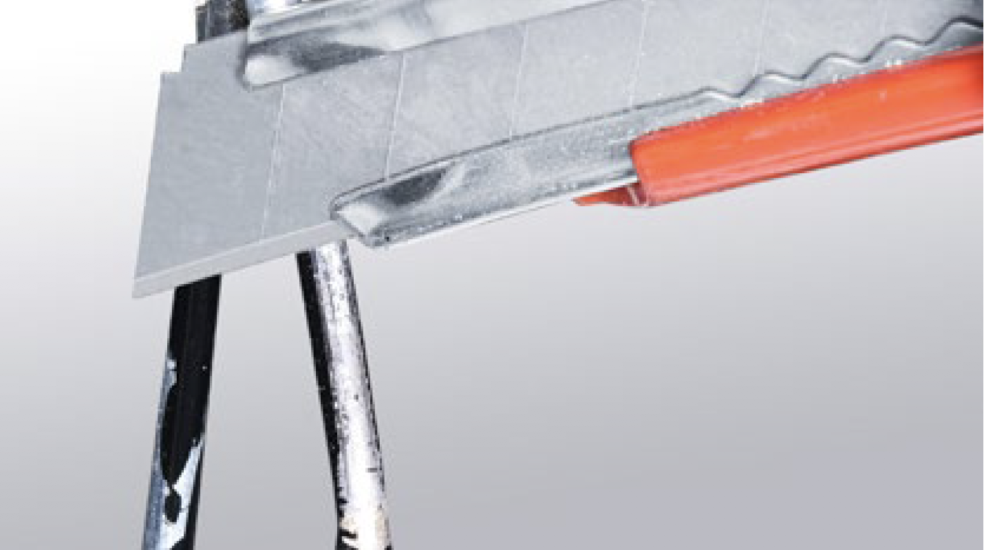
Step 5
Install quick connectoronto re-brazed pipe.

Step 6
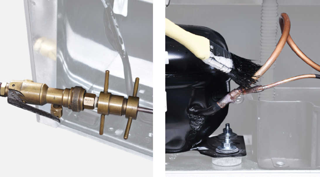
Inject nitrogen gas with 1.57Mpa pressure through quick connector into pipe.
Step 7
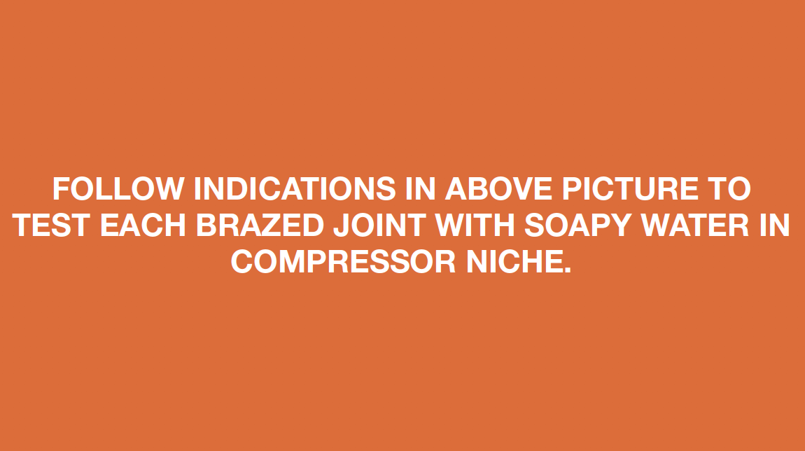
Please follow drawing below to perform a leakage test for brazed joints in the compressor niche.
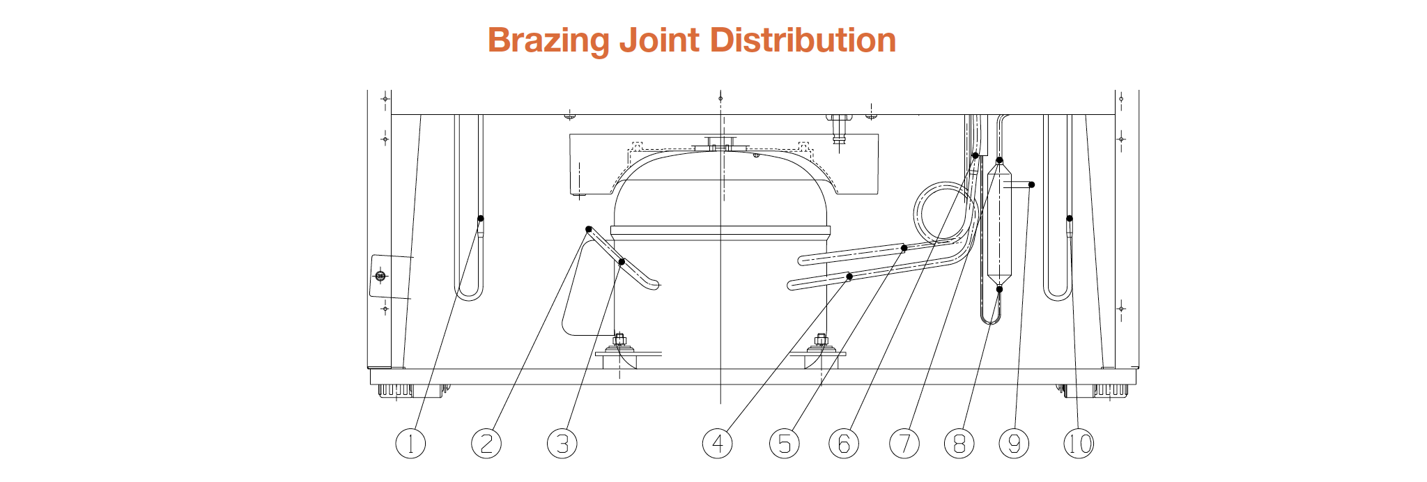
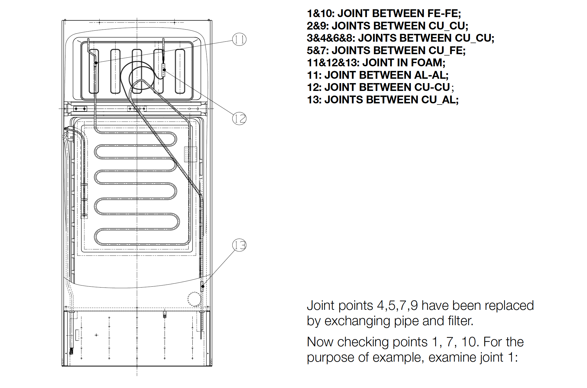

DIAGNOSIS 1
PROCEDURE 2
Step 1
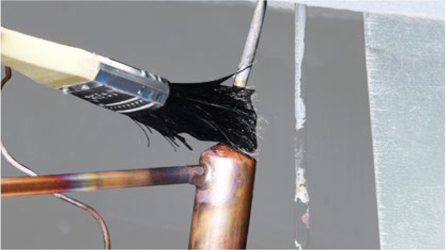
Clean paint from brazedjoint.

Step 2
Cut off brazed joint with leakage.
Step 3
Use a larger coppertube to connect 2
ends of brazed joint.

Step 4
Braze the 2 ends.

CHECK AND TEST 2
Step 1
Inject nitrogen at 1.57Mpathrough quick connector
into pipe and use soapy
water to perform leakage
test again.

DIAGNOSIS 2


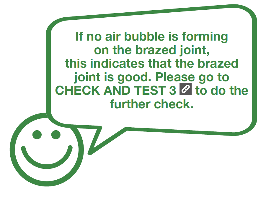
CHECK AND TEST 3
Step 1
Braze a piezometeronto processing tube of
compressor.
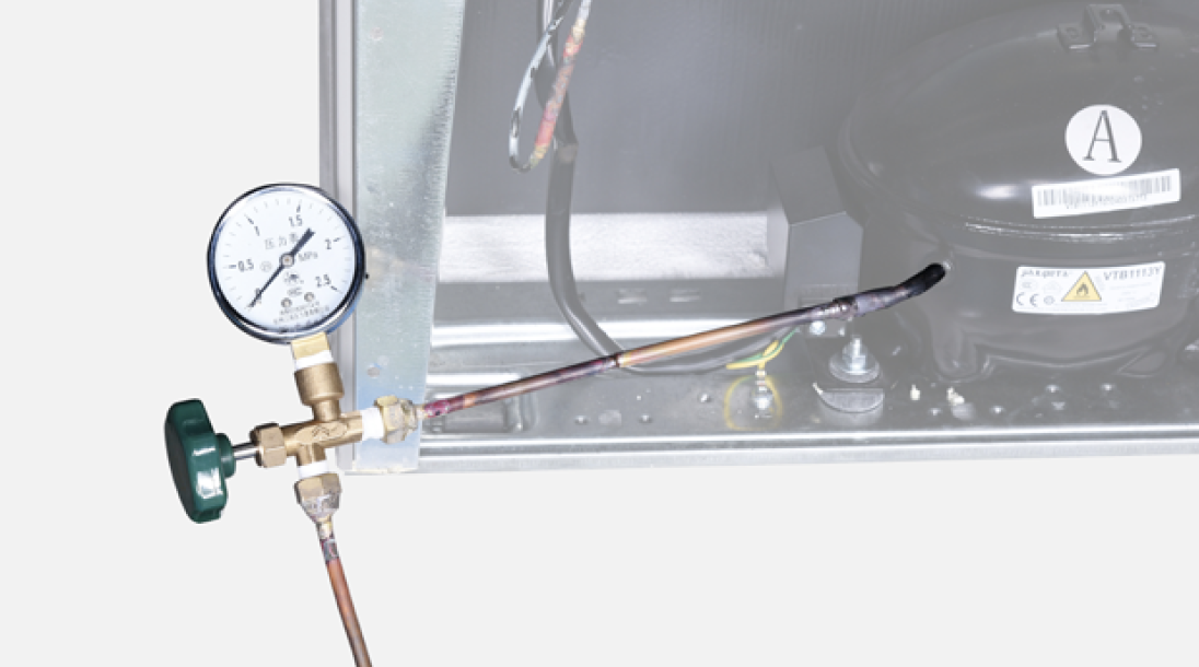
Step 2
Charge nitrogen at1.57Mpa through quick
connector into pipe.
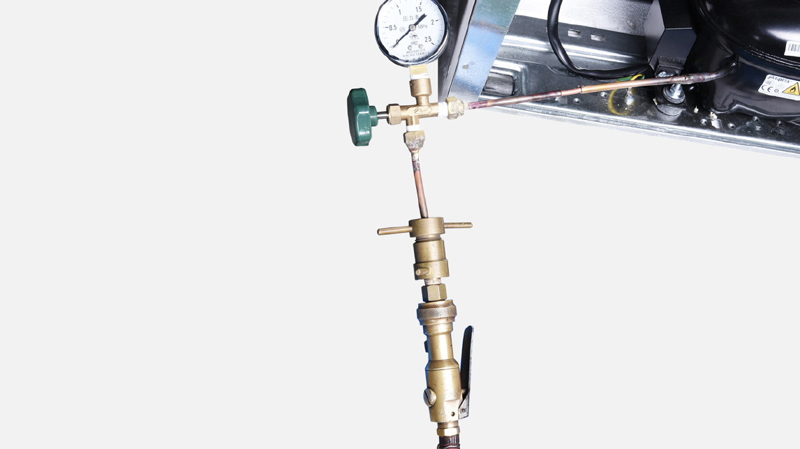
Step 3
Do leakage test onbrazing points and
piezometer.

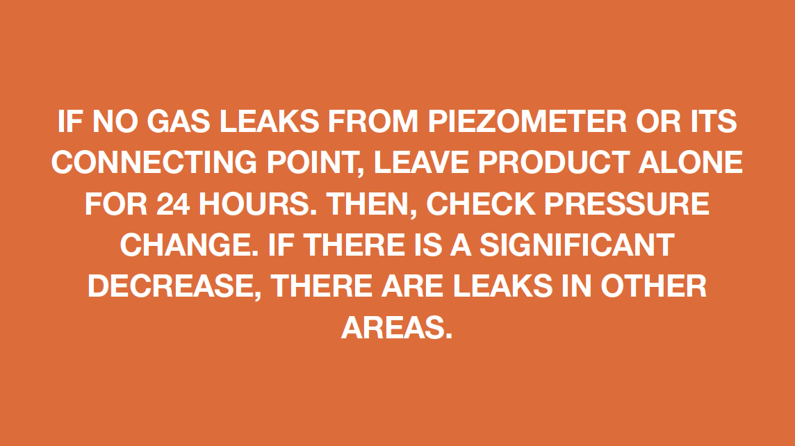
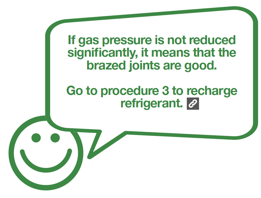
DIAGNOSIS 3
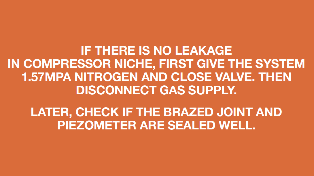
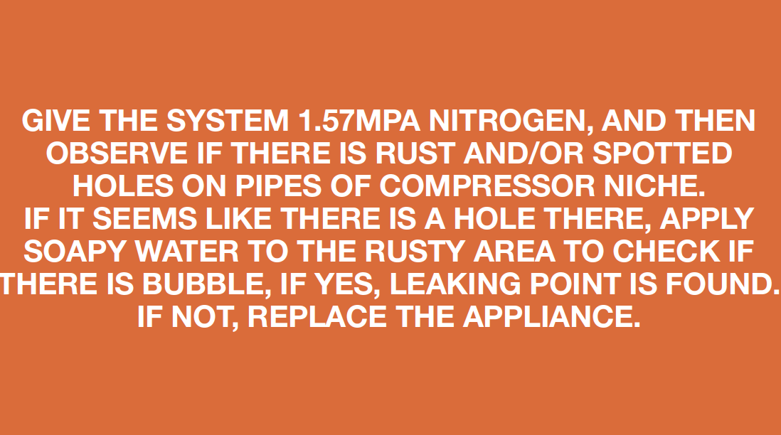
CHECK AND TEST 5
Step 1
Give the system
1.57Mpa Nitrogen, and
then observe if there is
rust and/or spotted holes
on pipes of compressor
niche.

Step 2
Apply soapy water torust area for leaking test.

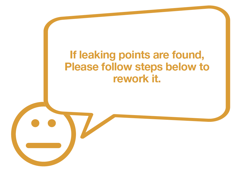
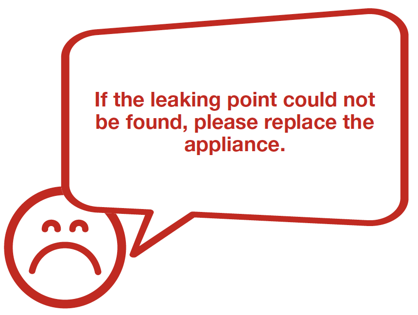
DIAGNOSIS 4
PROCEDURE 3

Step 1
Clean paint off brazedjoint of drying-filter.

Step 2
Cut off brazed jointwith leakage.
Step 3
Use a larger coppertube to connect 2
ends of brazed joint.
Step 4
Braze the 2 ends.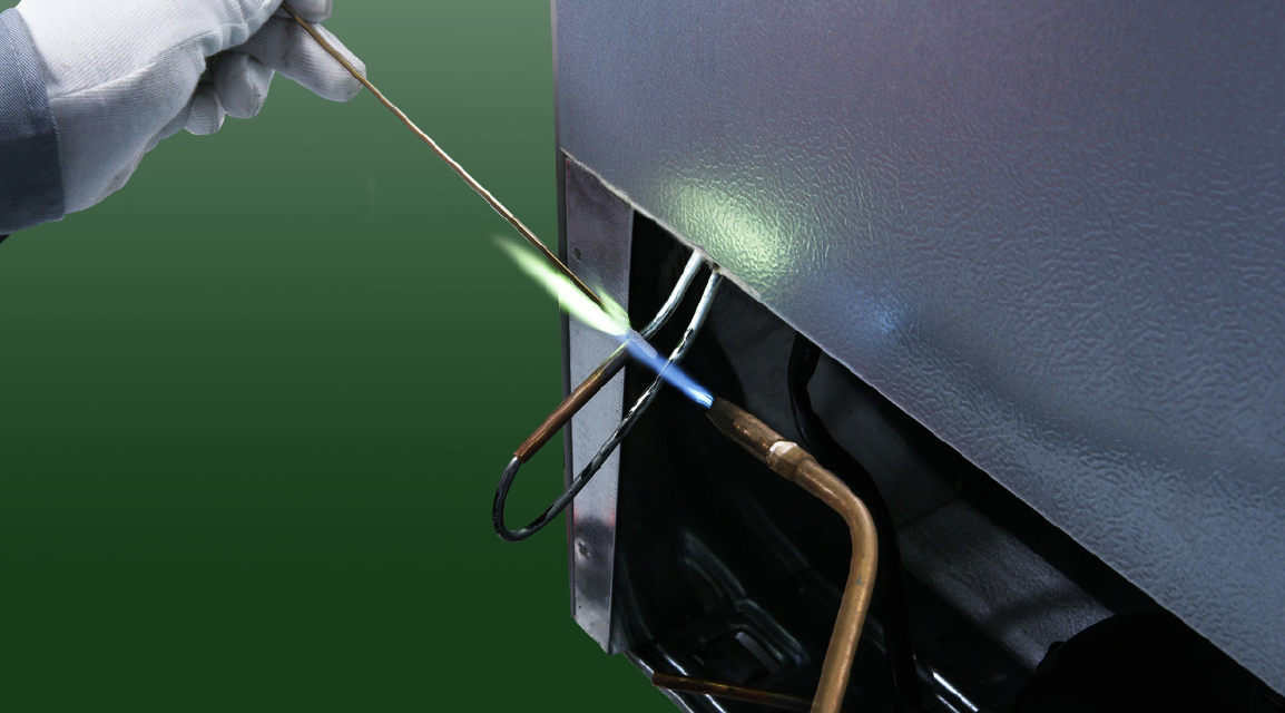

CHECK AND TEST 5
Step 5
Inject nitrogen at1.57Mpa through
quick connector into
pipe and use soapy
water to perform
leakage test again.
DIAGNOSIS 5


PROCEDURE 4
Step 1
Clean paint off brazedjoint of drying-filter.
Step 2
Cut off drying-filter.
Step 3
Cut off capillary andremove the cut end by
shaking.

Step 4
Braze one new drying- filter.
Step 5
Inject nitrogen (1.57Mpa) through quick connector into pipe for at least 3 min to blow remaining refrigerant away.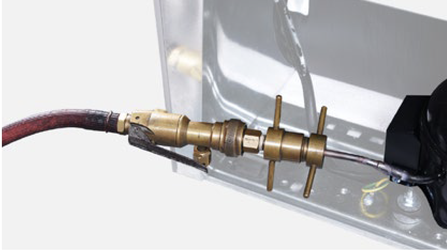
Step 6
Add quick connector onto processing pipe of drying-filter.
Step 7
Perform leakage test onbrazed joints of dryingfilter
and compressor
processing pipe.
Step 8
Vacuum and recharge.Click below link to get more details for vocuuming and gas-charging requirements, go to Annex B2

Step 9
Block processing pipe twice with locking pliers.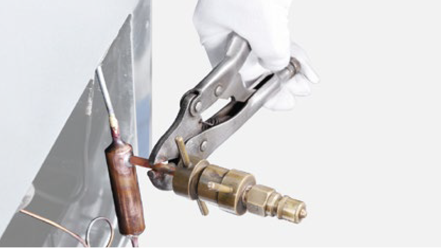
Step 10
Leave locking pliers on the second block and cut off the rest of the pipe by shaking.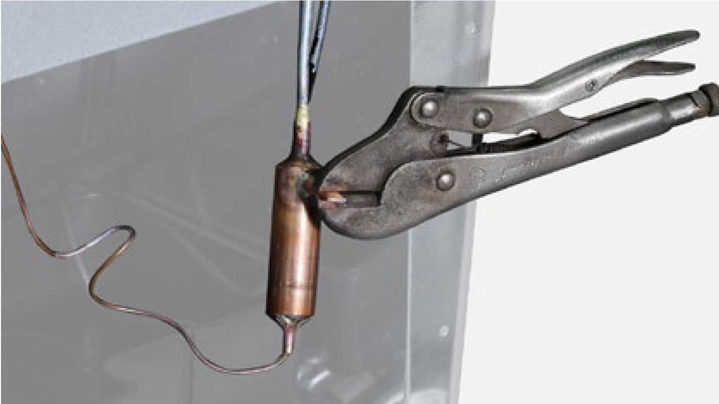
Step 11
Braze the ends and remove the pliers.
DIAGNOSIS 6


GO BACK TO COMPONENT LIST