
CHECK AND TEST 1
Step 1
Unscrew cover of mainboard with a cross-head screwdriver.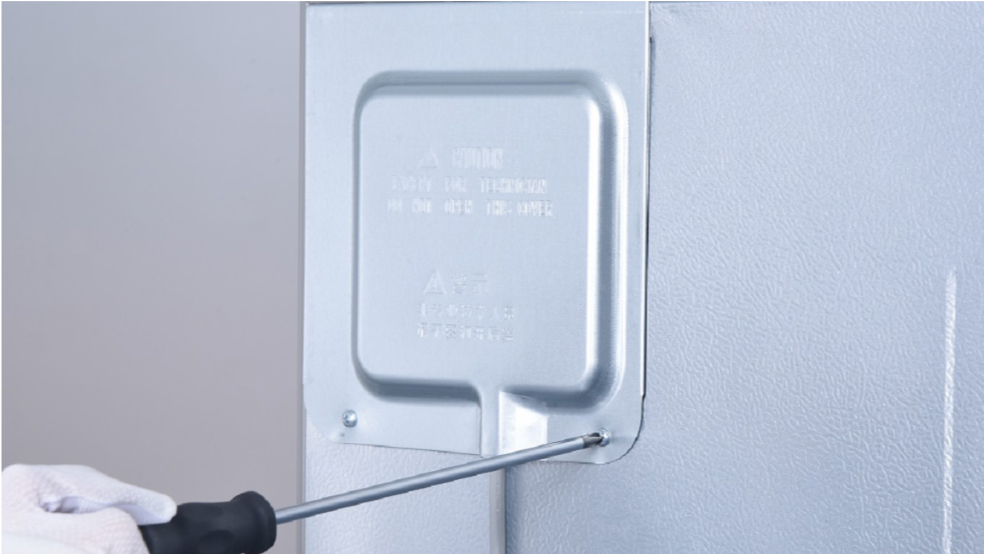
Step 2
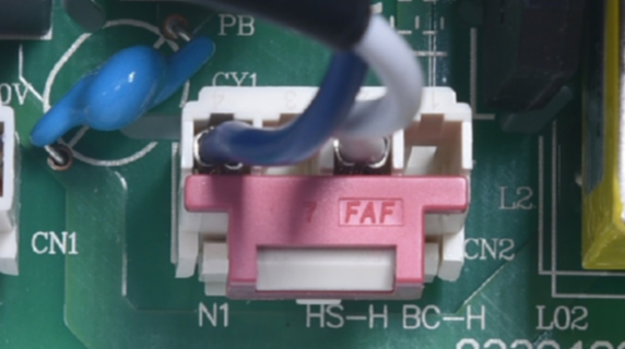
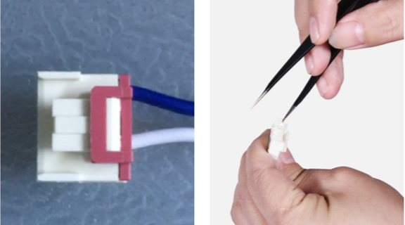
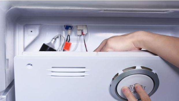
In PCB area, check if terminal is pushed into final position.
If not, redo it.
Step 3
In PCB area, check if terminal is filled with foam.
Step 4
Remove foam with
tweezers.
Step 5
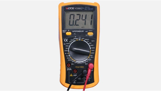
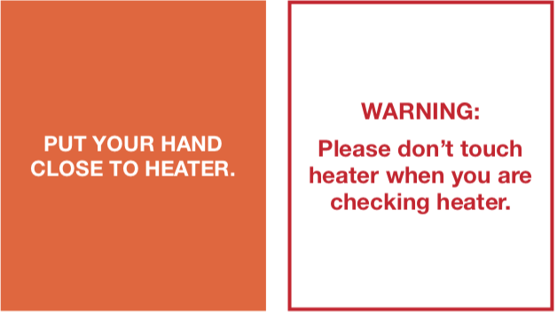
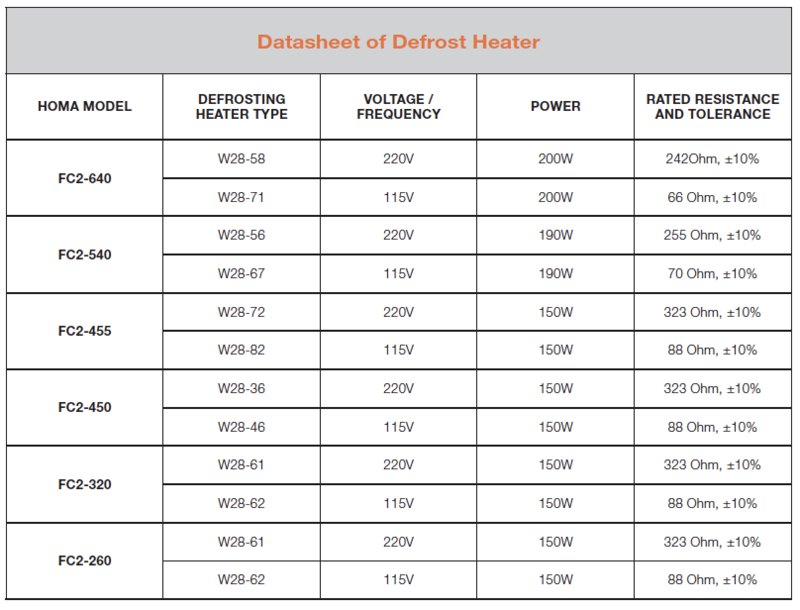
Measure resistance of heater from terminal in PCB area.

Step 6
Check the result.

DIAGNOSIS 1


PROCEDURE 1
Step 1
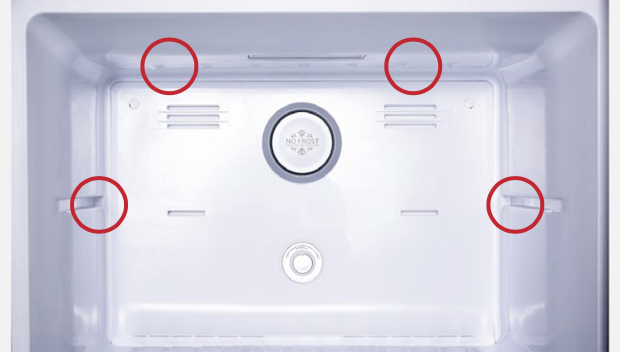
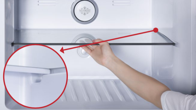
Remove freezer shelf.
Step 2
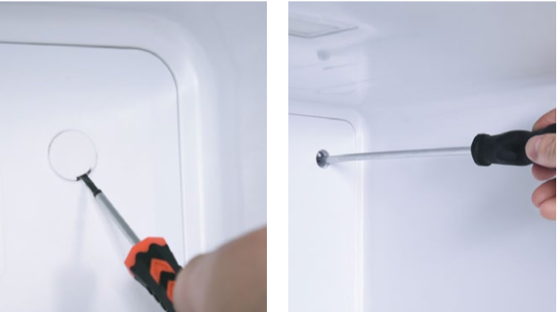
Lever 2 screw covers off.
Step 3
Unscrew 2 screws.
Step 4
Remove air duct:
a.Hold the decorative cover of air duct;
b. Pull air duct out;

c. Disconnect the terminal of fan motor;

d. Take air duct away.
d. Take air duct away.

CHECK AND TEST 2
Step 1
Check if terminal is pushed into final
position.
If not, please re-insert the
terminal into the buckle.

Step 2
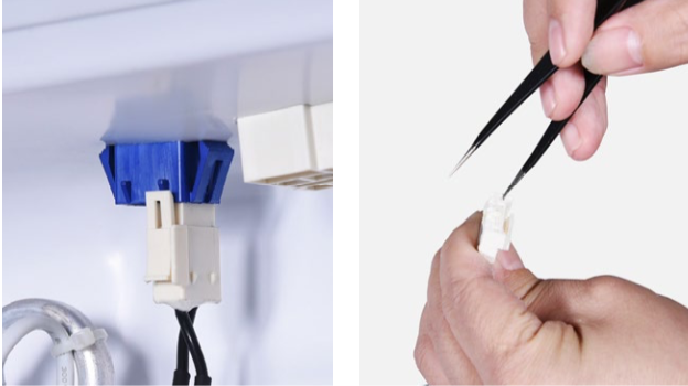
Check if the terminal is filled with foam.
Step 3
Remove foam with tweezers.
Step 4
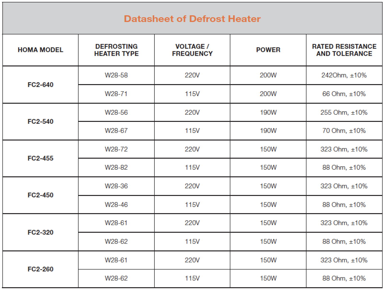
Measure the resistance of heater from terminal in freezer.

DIAGNOSIS 2


PROCEDURE 2

Step 1
Disconnect the terminal of heater.
Step 2
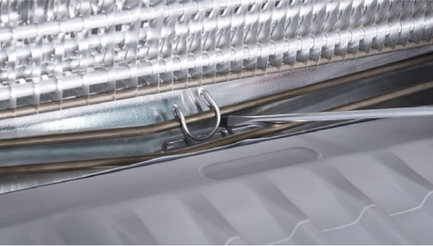
Take out heat- conducting rod with slotted screw driver.
Step 3
Use 6mm cross-head driver to unscrew on left and right.

Step 4
Lift evaporator and heater 20mm, the bottom must be higher than the edge of the trough.

WARNING:
Be careful not to deform
pipes in red square
during steps 4 & 5.
WARNING:
Be careful not to deform pipes in red square during steps 4 & 5.
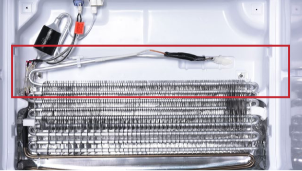
Step 5
Loosen the clips for fastening heater. There are 8 clips in total.
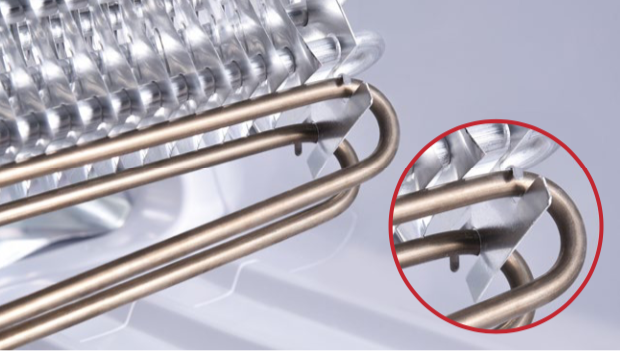
Step 6
Remove the heater.

Reverse procedures
above to reinstall the
heater.
Reverse procedures above to reinstall the heater.
Step 7
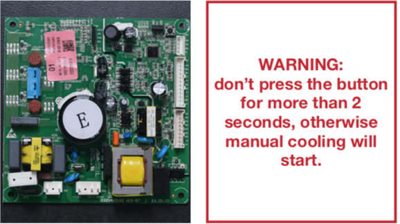
Please press the button SW1 on mainboard (within 1 minute of powering on the appliance) to start manual defrost.

DIAGNOSIS 3

CHECK AND TEST 3
Step 1
Connect 2 ends on terminal in PCB area.
Step 2
Check the connection of wires in foam.


DIAGNOSIS 4

Tip 1
When reinstalling air duct, move wires out of the way to prevent crushing by air duct.
Tip 2
After pushing air duct back into position, you should hear a clicking sound. If there is no click, please repeat again.
Tip 3
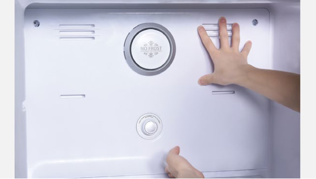
Check to see if there is a wide gap between air duct and cabinet.
If gap is large, re-install air duct.
