

CHECK AND TEST 1
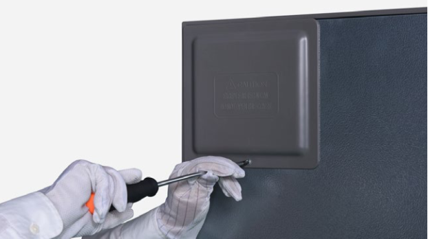
Step 1
Unscrew cover of mainboard with a Cross-head screwdriver.
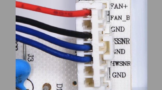
Step 2
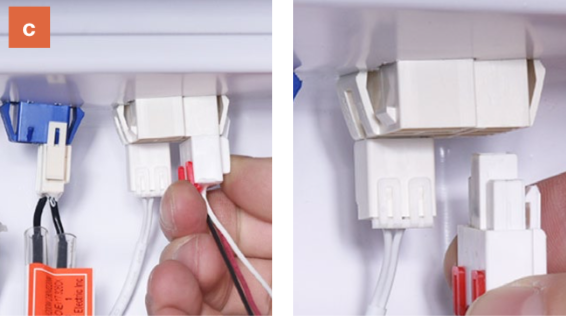
In PCB area, check if terminal is pushed into final position.
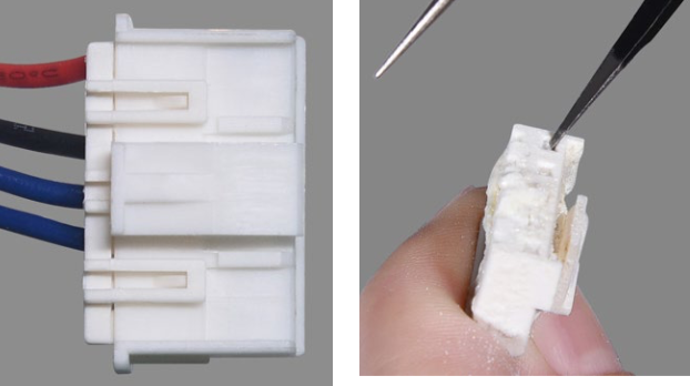
Step 3
In PCB, check to see if terminal is filled with foam.
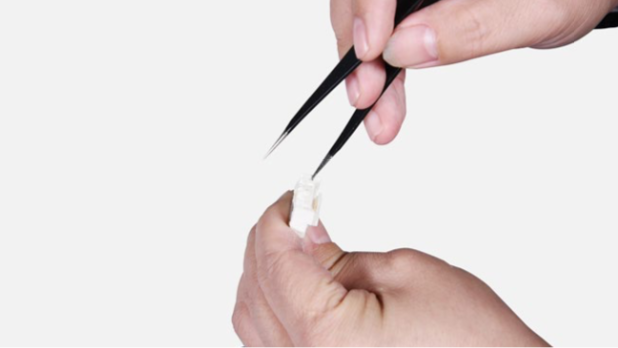
Step 4
If so, use tweezers to remove it.
Step 5
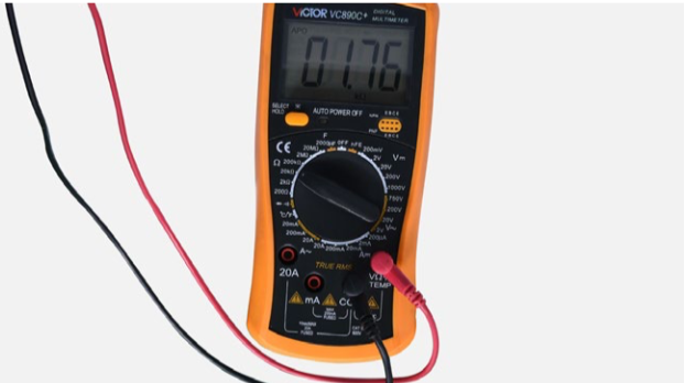
In PCB area, use multimeter to measure resistance value.
Step 6
Take note of the result.
Step 7
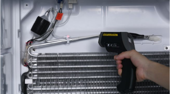
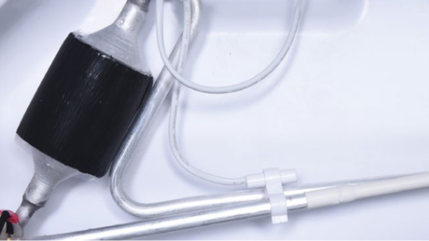
Measure the temperature of freezer air duct, close to sensor.

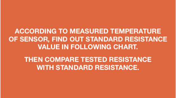
DIAGNOSIS 1


PROCEDURE 1

Step 1
Remove freezer shelf.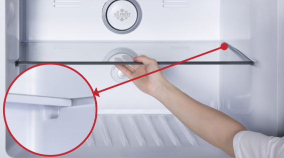
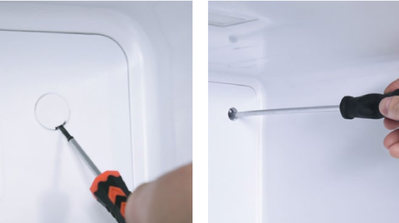
Step 2
Lever 2 screw covers off.
Step 3
Unscrew 2 screws.
Step 4
Remove air duct:a. Hold the decorative cover of air duct;
b. Pull air duct out;
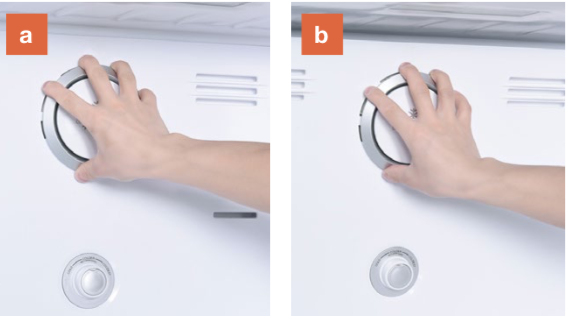
c. Disconnect the terminal
of fan motor;
d. Remove freezer air duct.
DIAGNOSIS 2


PROCEDURE 2

Step 1
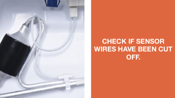
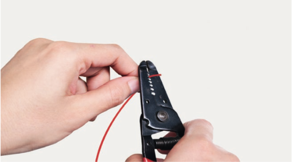
Cut wire off from broken area.
Step 2
Peel off the sleeves.
Step 3
Check to ensure proper wire order and connect them.

Step 4
Tin soldering.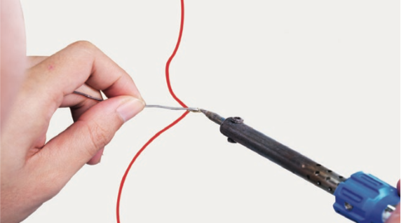
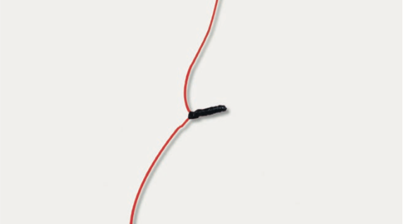
Step 5
Cover connection with electrical tape.
Step 6
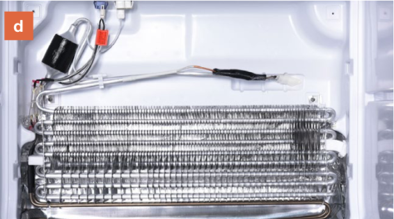
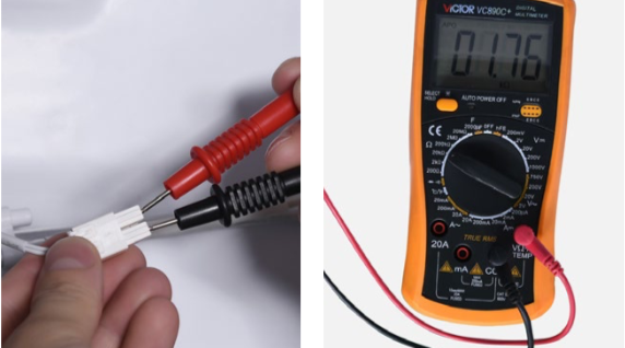
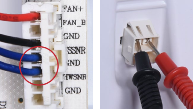
Use a multimeter to measure the resistance value of defrosting temp. sensor from terminal located in freezer.
Insert the detectors into terminal and measure the resistance of sensor.
Take note of the result.
Step 7
Measure the temperature of sensor.
DIAGNOSIS 3


CHECK AND TEST 2
Step 1
Check to see if the terminal is filled with foam.
Step 2
If so, use a tweezers to remove it.
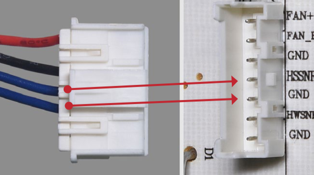
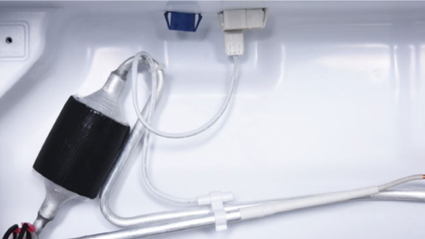
Step 3
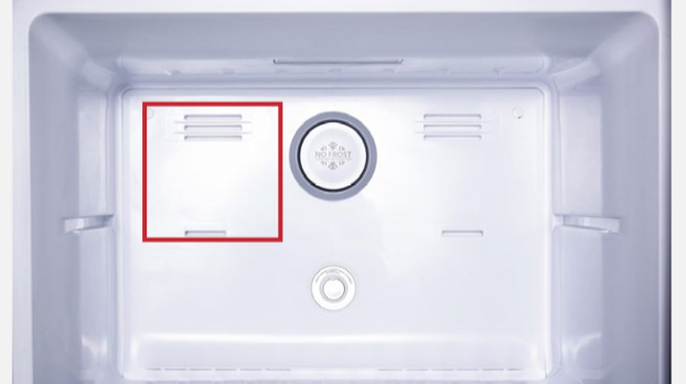
Make sure sensor is properly located by comparing with photo on right.
If sensor is not in same position as photo, follow the indication of picture to fix it.
Step 4
Connect the 2 ends in PCB area.
DIAGNOSIS 4
Step 1
testo testo

PROCEDURE 3
Tip 1
When reinstalling air duct, move wires out of the way to prevent crushing by air duct.
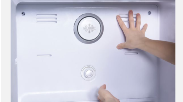
Tip 2
After pushing air duct back into position, you should hear a clicking sound. If there is no click, please repeat again.
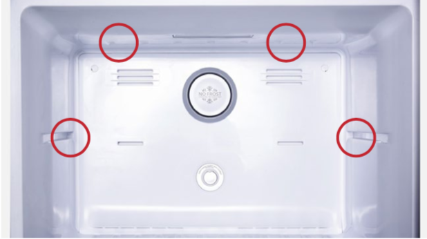
Tip 3
Check to see if there is a wide gap between air duct and cabinet.
If gap is large, re-install air duct.

GO BACK TO COMPONENT LIST