

CHECK AND TEST 1
Step 1
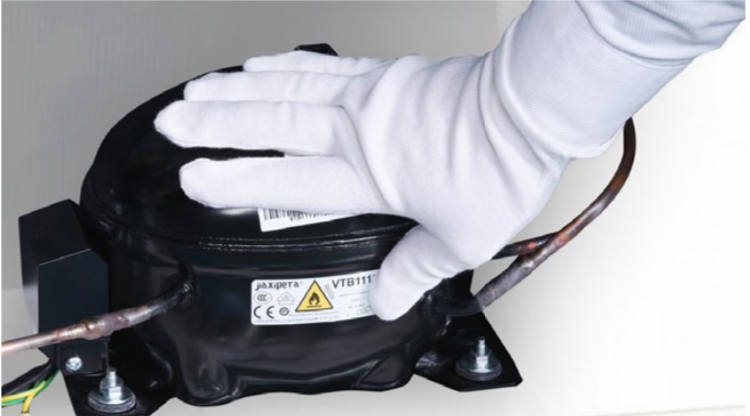
Plug in. The compressor starts, but the protection is activated immediately, and it cannot work normally. Put hand onto compressor, no shaking can be felt.
Step 2
Measure the AC voltage of the compressor with a multimeter. If voltage of three terminals are almost the same (100V~200V), it means power is transferred to compressor.
SAFETY ATTENTION: MAKE SURE DETECTORS NOT TOUCH EACH OTHER. HANDS DON’T TOUCH LIVE PART.

Step 3
Wait a few minutes,
repeatedly power on and
off several times, the
compressor starts but
activates protection.


DIAGNOSIS 1

CHECK AND TEST 2
Step 1
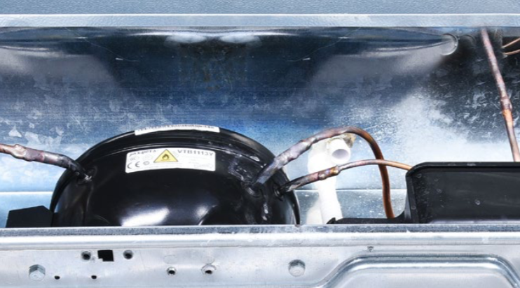
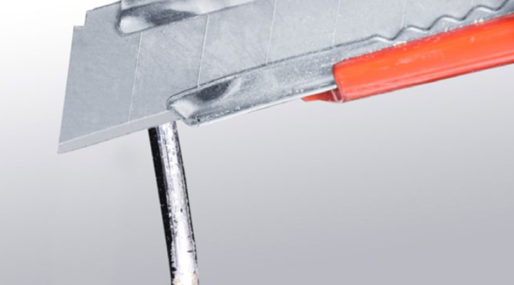
Cut off capillary to discharge refrigerant.

Step 2
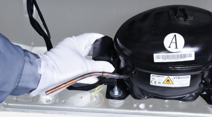
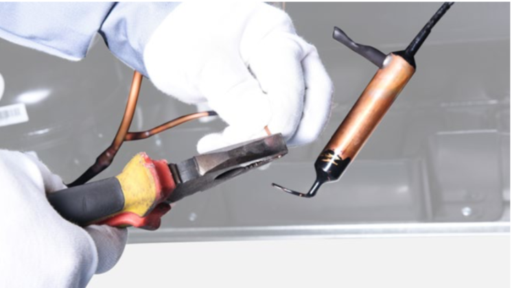
Cut off exhaust pipe and suction pipe

Step 3
Power up the compressor and feel the exhaust pressure of the exhaust pipe with a paper.

DIAGNOSIS 2


PROCEDURE 2

Step 1
Unscrew terminal cover.

Step 2
Remove terminal cover.
Step 3
Move out protector and starter.
Step 4
Unscrew earthing wire.

Step 5
Unscrew nut of compressor.

Step 6
Put on a new compressor and fix nuts onto compressor.

Step 7
Braze the joints of suction and exhasuting pipes.
Step 8
Re-braze a copper tube onto processing tube of compressor.
To get more details on brazing requirements, please go to page 631.

Step 9
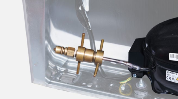
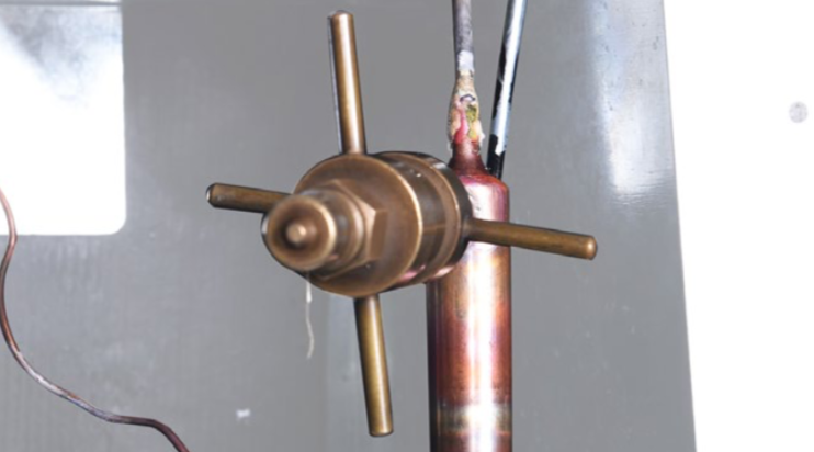
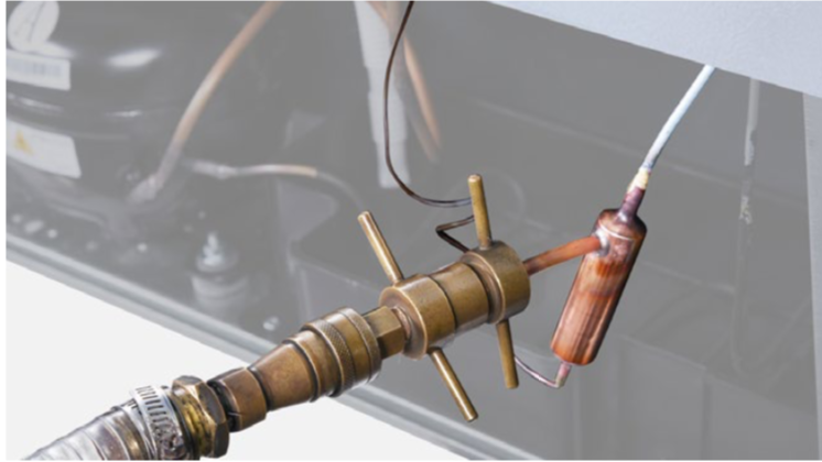
Install quick connector onto re-brazed pipe.

PROCEDURE 2

Step 1
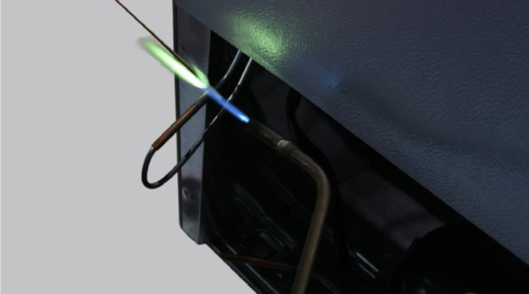
Clean away paint on brazed joint of drying-filter.
Step 2
Cut off drying-filter.
Step 3
Cut off capillary and remove the cut end by shaking.

Step 4
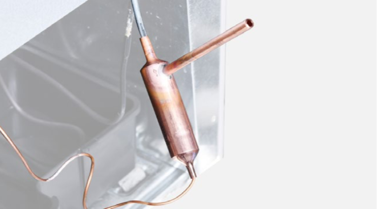
Braze on a new drying-filter.
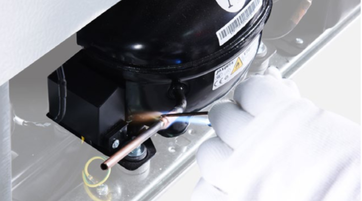
Step 5
Re-braze a copper tube onto processing tube of compressor.
To get more details on
brazing requirements,
please go to Annex B1.

Step 6
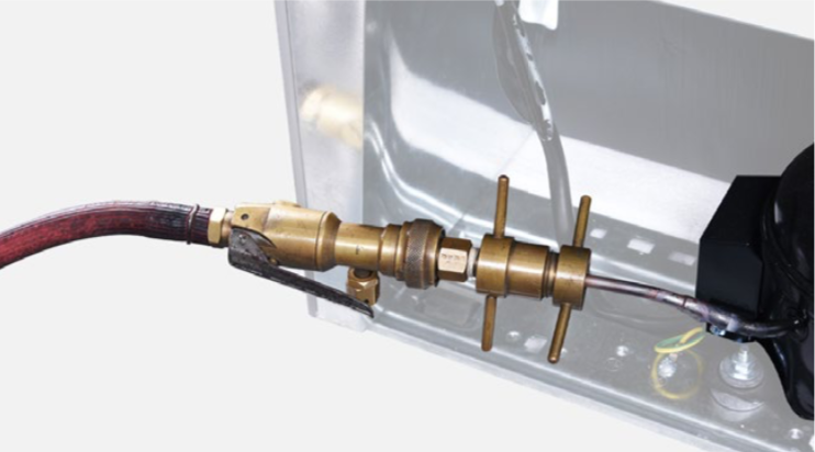
Inject nitrogen (1.57Mpa)
through quick connector
into pipe for at least
3 min to blow left
refrigerant away.
Step 7
Add quick connector onto processing pipe of drying-filter.
Step 8
Do leakage test on brazed joints of drying- filter and compressor processing pipe.
Step 9
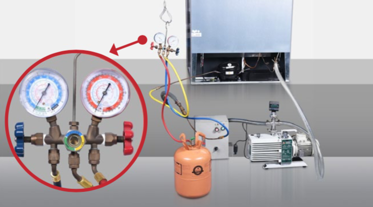
Vacuum and recharge.
Click below link to get more details for vacuuming and gas- charging requirements, on Annex B1.
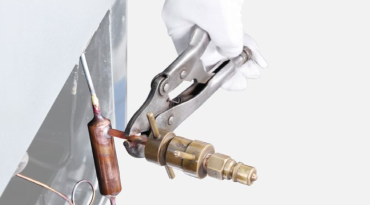
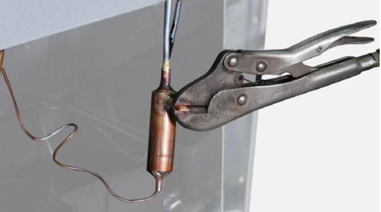
Step 10
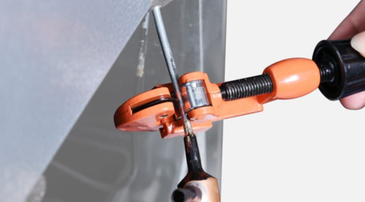
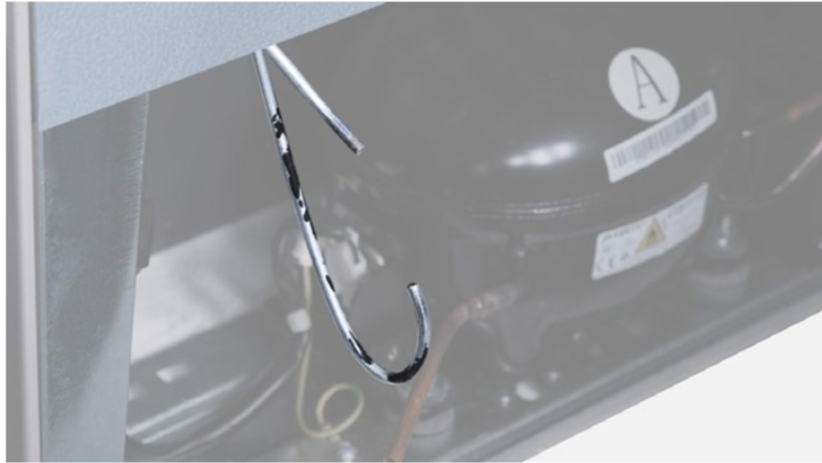
Block processing pipe twice with locking pliers.
Step 11
Leave locking pliers on the second block and shake to cut off the rest of pipe.
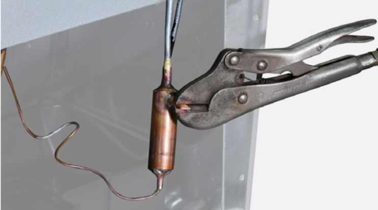
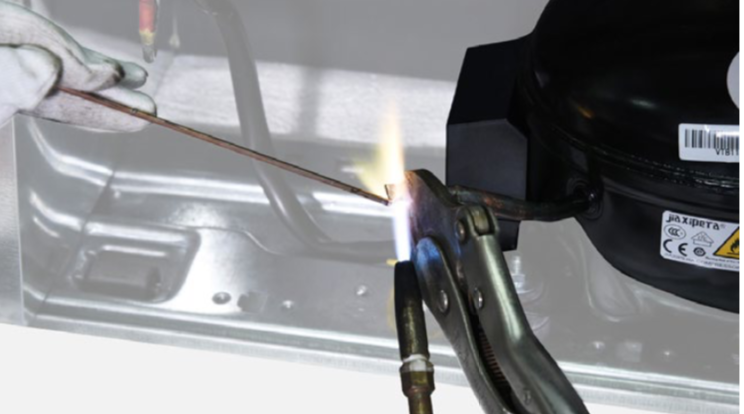
Step 12
Braze the ends and remove the pliers.

DIAGNOSIS 3


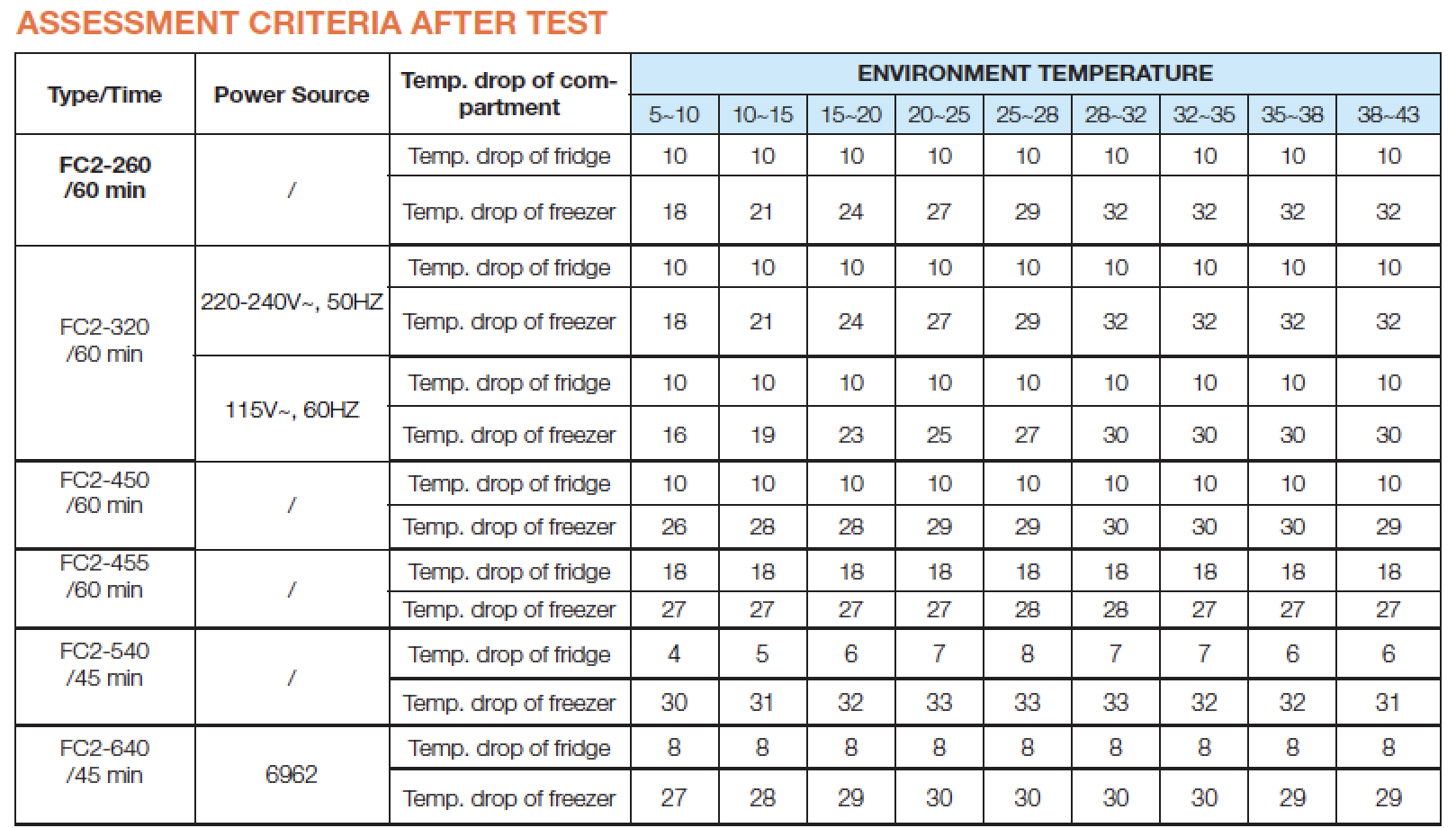
Performance Testing Procedures and Assessment Criteria for FC2 Series
Test conditions
1 Ambient temperature and humidity are the same as natural conditions.
2 Sensor position close to air outlet.
3 Testing time 45 or 60 minutes.
4 Set thermostat to MAX.
CHECK AND TEST 3
Step 1
Clean away paint on brazed joint of drying-filter.

Step 2
Cut off drying-filter.

Step 3
Cut off capillary and remove the cut end by shaking.
Step 4
Braze on a new drying-filter.
Step 5
Add quick connector
onto processing pipe of
drying-filter.

Step 6
Inject nitrogen (1.57Mpa) through quick connector into pipe.
Step 7
Cut off brazed joints, one by one, at high pressure end.

Step 8
Every time a joint is cut off, check whether the gas pressure from suction pipe is reduced or not.

DIAGNOSIS 4


PROCEDURE 3

Step 1
Use a larger copper tube to connect 2 ends of brazed joint.

Step 2
Weld the 2 ends.
To get more details on brazing requirements, please go to Annex B1.

PROCEDURE 4

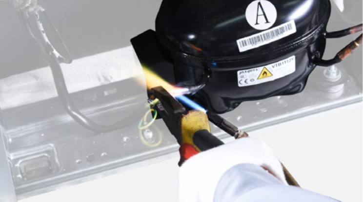
Step 1
Melt brazing material with flame and pull out processing tube using a pair of pliers.
Step 2
Re-braze a copper tube onto processing tube of compressor.
To get more details on
brazing requirements,
please go to Annex B1.
Step 3
Install quick connector onto processing pipe.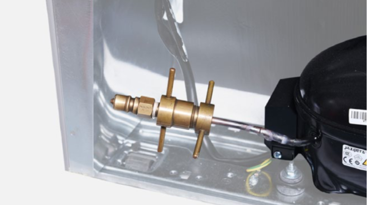
Step 4
Inject nitrogen (1.57Mpa)
through quick connector
into pipe for at least
3 min to blow left
refrigerant away.

Step 5
Do leakage test on brazed joints of drying- filter and compressor processing pipe.

Step 6
Vacuum and recharge.
Click below link to get more details for
vacuuming and gas-
charging requirements,
on Annex B1.

Step 7
Block processing pipe twice with locking pliers.

Step 8
Leave locking pliers on the second block and shake to cut off the rest of pipe.
Step 9
Braze the ends and remove the pliers.
DIAGNOSIS 5

Performance Testing Procedures and Assessment Criteria for FC2 Series
Test conditions
1 Ambient temperature and humidity are the same as natural conditions.
2 Sensor position close to air outlet.
3 Testing time 45 or 60 minutes.
4 Set thermostat to MAX.


GO BACK TO COMPONENT LIST