

PROCEDURE 1
Note
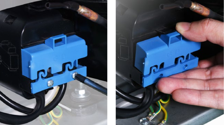
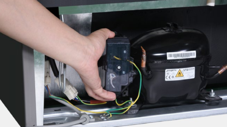
Starter and protector is covered by plastic cover, you need to disassemble and remove the cover.

Step 1
Unscrew interlocking plastic.
Step 2
Remove the blue plastic.
Step 3
Lever off the terminal box.
Step 4
Pull out integrated protector and starter.

Step 5
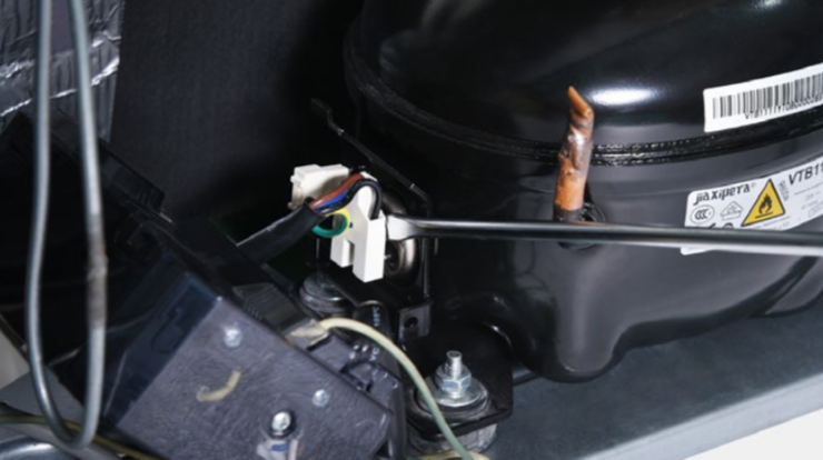
Disconnect terminals.

CHECK AND TEST 1
Step 1
Put the pin into the hole connected with compressor to do the test.

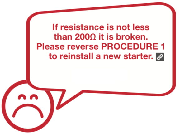
DIAGNOSIS 1


CHECK AND TEST 2
Step 1
Put the pin into the hole connected with compressor to test.

Step 2
Assess results.

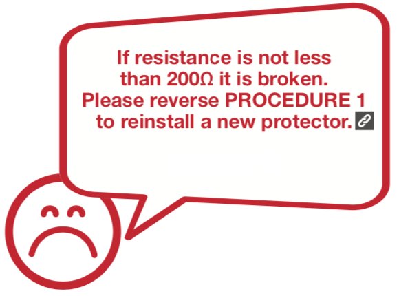
DIAGNOSIS 2


CHECK AND TEST 3
Step 1
Watch the warning light flashing on the inverter box.

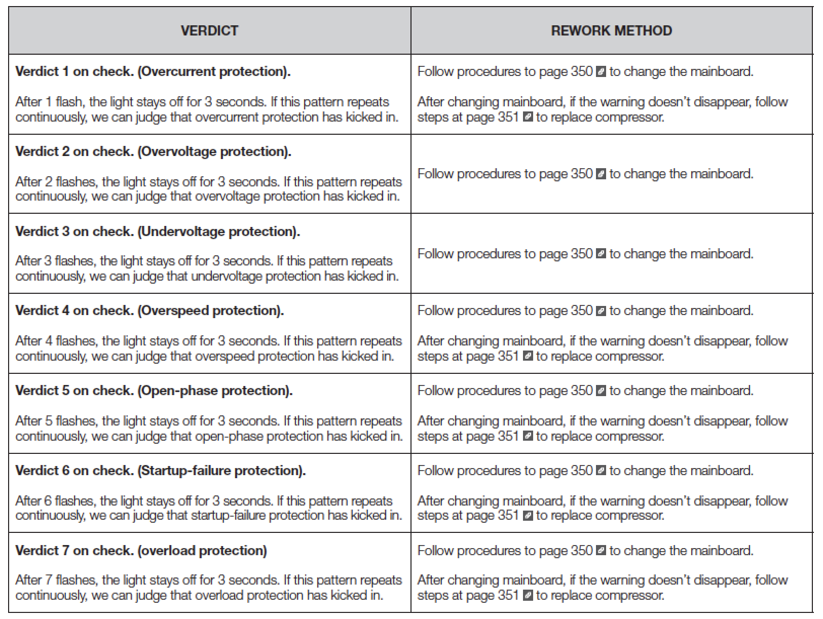
DIAGNOSIS 3


PROCEDURE 2

Step 1
Pull up to remove inverter box.
Step 2
Disconnect terminals.
Step 3
Disconnect power cord.

Step 4
Disconnect terminals.
Reverse above
steps to install
a new inverter box.

DIAGNOSIS 4


PROCEDURE 3

Step 1
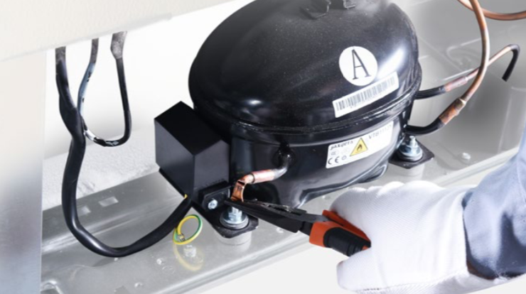
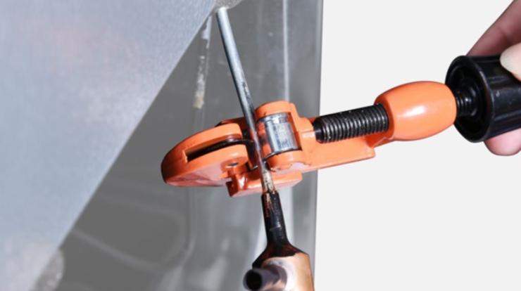
Discharge refrigerant.Cut off the charging tube with a pair of pliers.
Step 2
Discharge all refrigerant toward the exhaust vent.
Step 3
Cut off exhaust pipe and suction pipe

Step 4
Unscrew nut of compressor.

Step 5
Put on a new compressor and fix nuts onto compressor.

Step 6
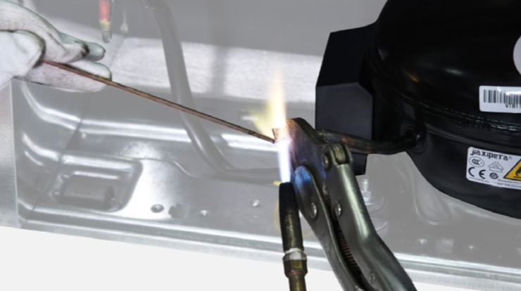
Braze the joints of suction and exhasuting pipes.
Step 7
Re-braze a copper tube onto processing tube of compressor.
To get more details on brazing requirements, please go to Annex B1.


PROCEDURE 4

Step 1
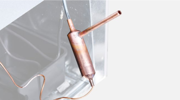
Clean away paint on brazed joint of drying-filter.

Step 2
Cut off drying-filter.
Step 3
Cut off capillary and remove the cut end by shaking.

Step 4
Braze on a new drying-filter.
Step 5
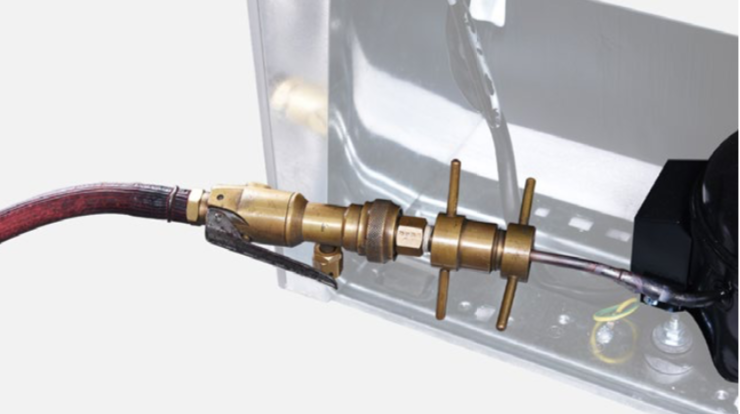
Inject nitrogen (1.57Mpa)
through quick connector
into pipe for at least
3 min to blow left
refrigerant away.
Step 6
Add quick connector onto processing pipe of drying-filter.
Step 7
Do leakage test on
brazed joints of drying-
filter and compressor
processing pipe.

Step 8
Vacuum and recharge.
Click below link to get more details for
vacuuming and gas-
charging requirements,
on Annex B1

Step 9
Block processing pipe twice with locking pliers.
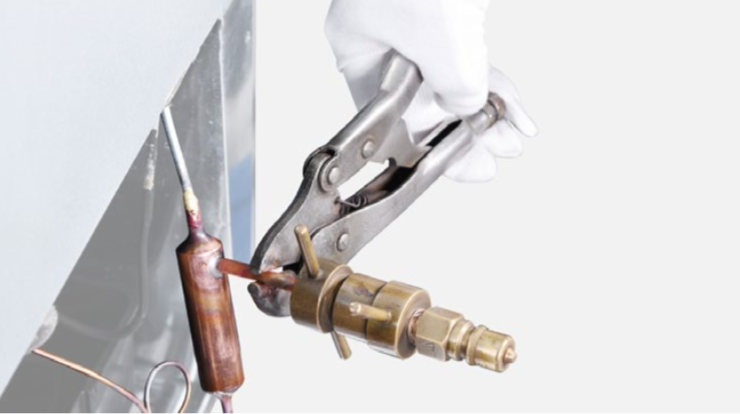
Step 10
Leave locking pliers on the second block and shake to cut off the rest of pipe.

Step 11
Braze the ends and remove the pliers.
DIAGNOSIS 5


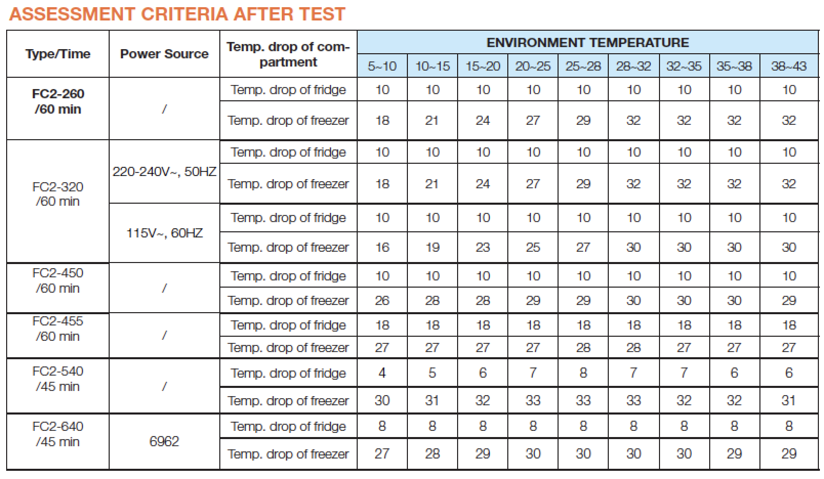
Performance Testing Procedures and Assessment Criteria for FC2 Series
Test conditions
1 Ambient temperature and humidity are the same as natural conditions.
2 Sensor position close to air outlet.
3 Testing time 45 or 60 minutes.
4 Set thermostat to MAX.

GO BACK TO COMPONENT LIST