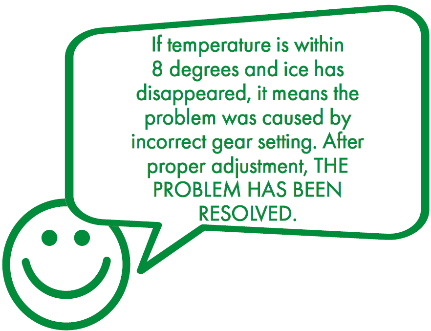
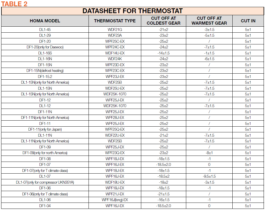
CHECK AND TEST 1
Step 1
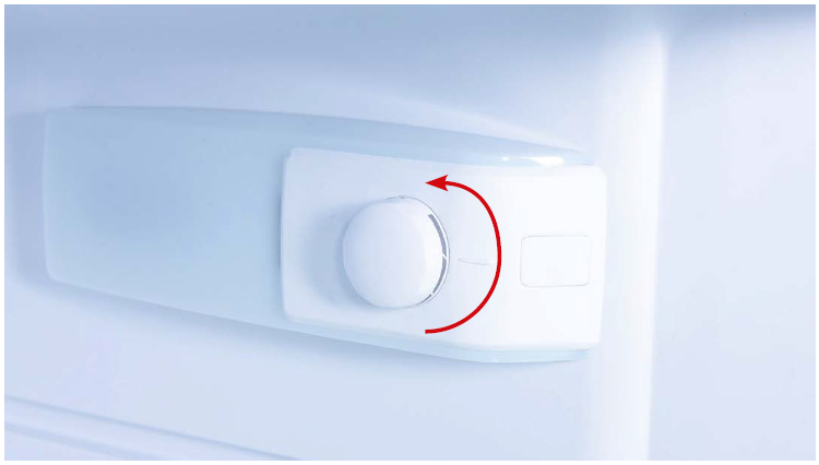
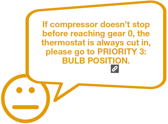
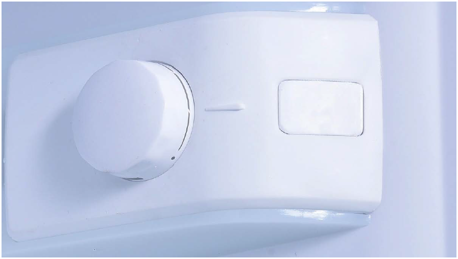
Check thermostat gear. If gear is set to 6 or 7 and compressor is running, turn knob slowly to lower until the compressor stops.
Step 2
If compressor stops before reaching gear 0, please continue to reduce the gear by 0.5, and let appliance run for 1 day to reach stable status.
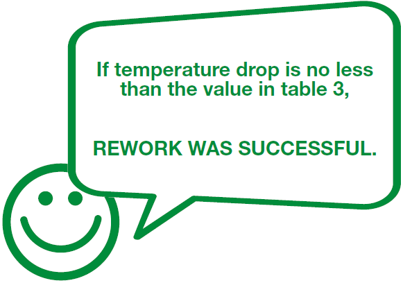
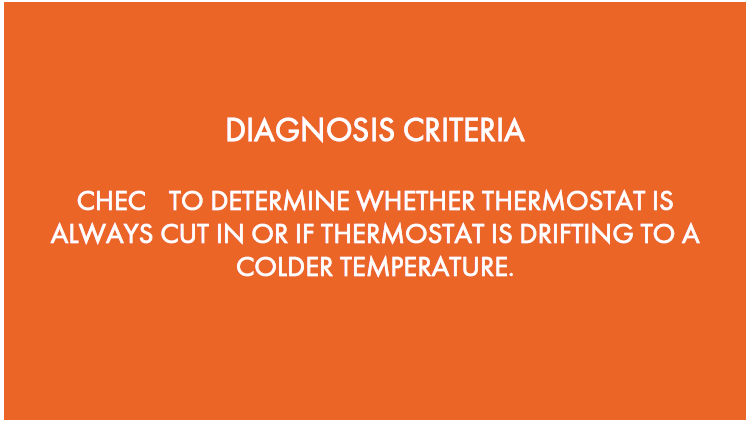
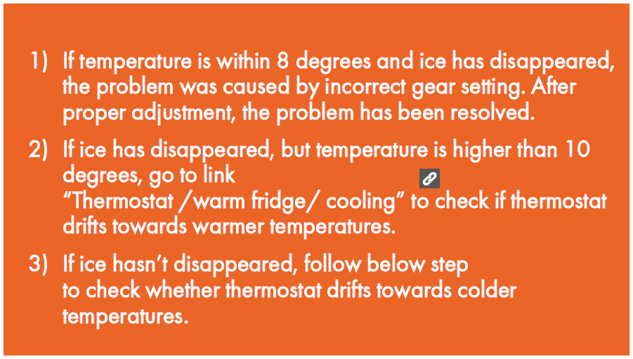
DIAGNOSIS 1

CHECK AND TEST 2
Step 1
When compressor stops before turning knob to
gear 1, please reduce gear by 0.5.

Step 2
After letting the appliance run for 1 day,
please check internal temperature and verify
whether there is any ice.

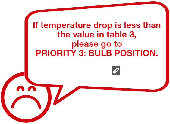
DIAGNOSIS 2
CHECK AND TEST 2
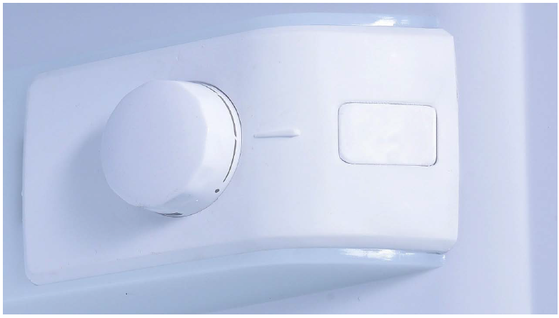
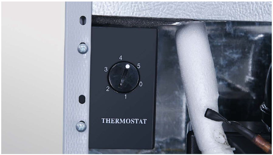
Step 1
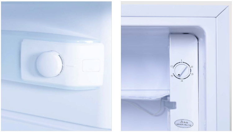
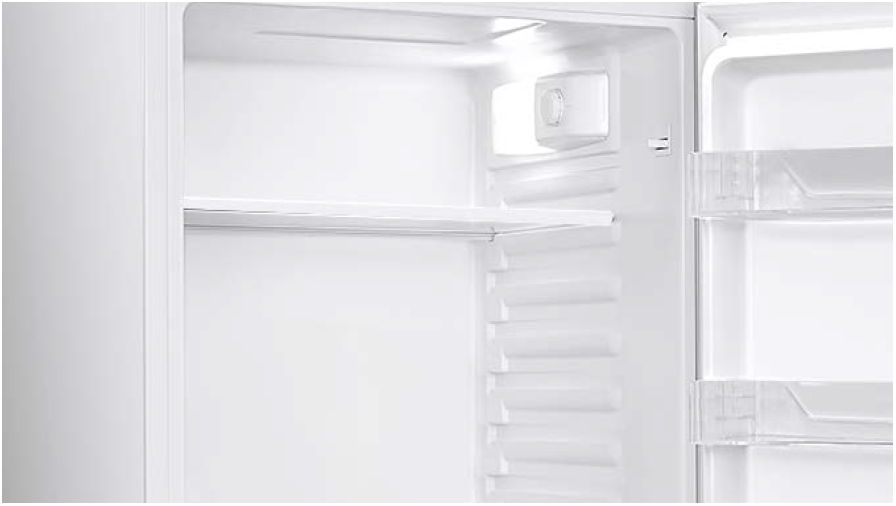
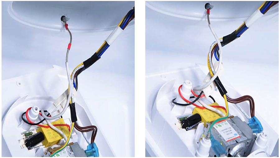
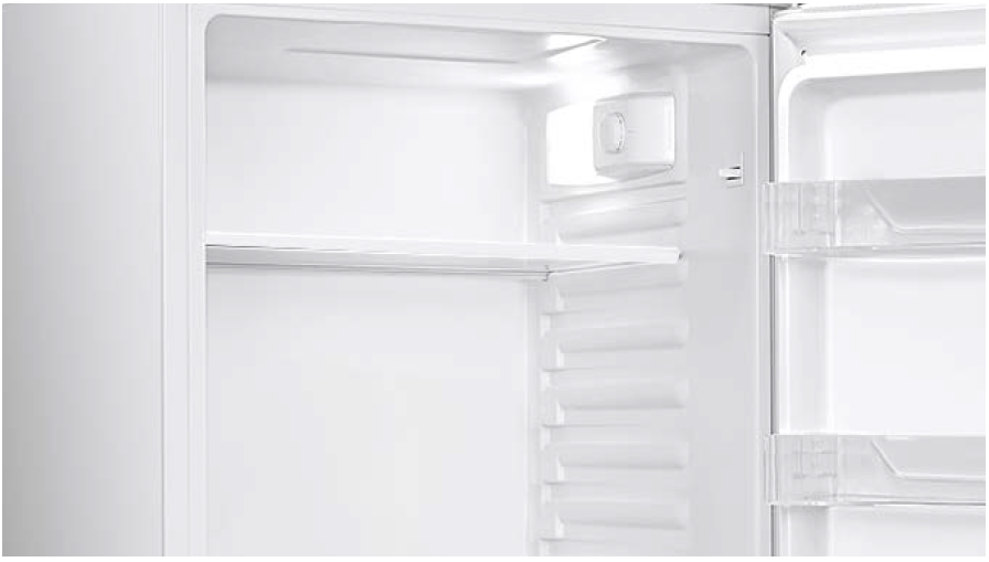
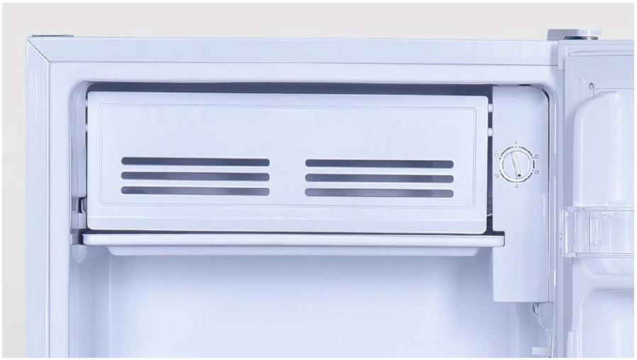
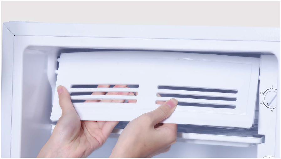
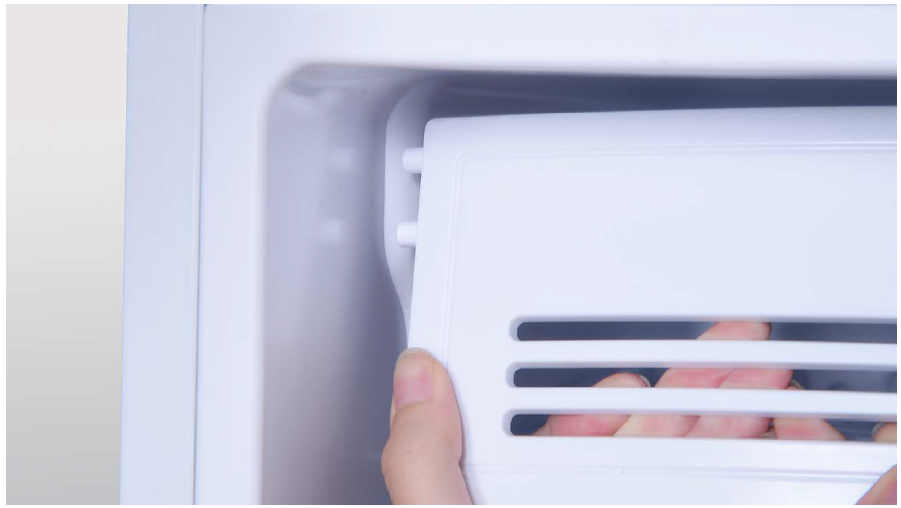
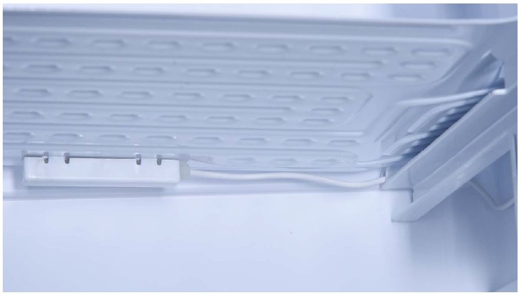
Set thermostat control knob to gear Min, and switch on the appliance. According to model name in rating label, study diagram below to find position of thermostat bulb.
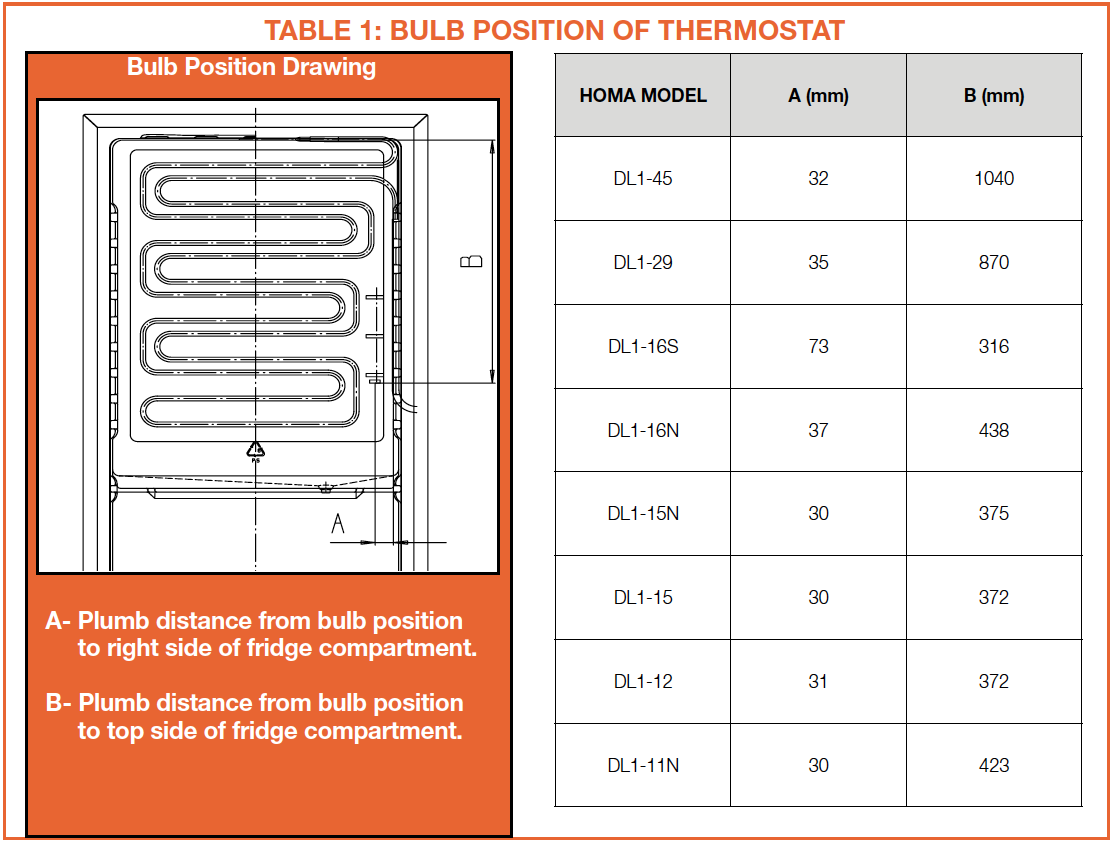
For visible evaporator
Please find out termostat bulb postition on the surface of evaporator.
Step 3
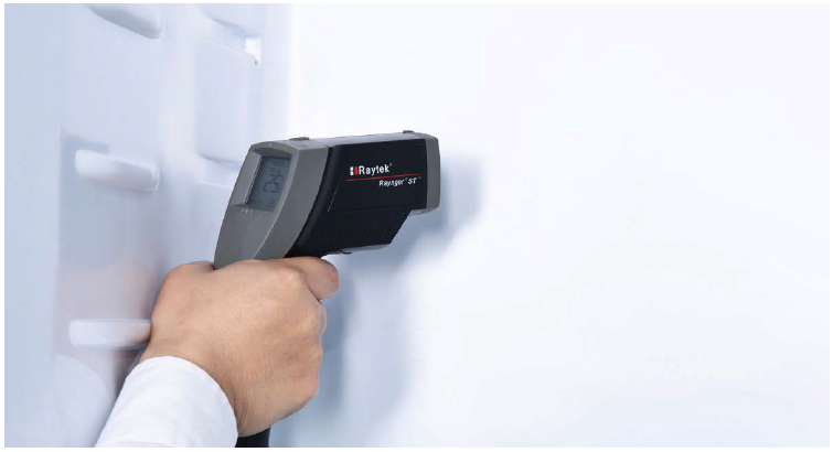
Perform following 2 tests:
1. When compressor stops for second time, measure temp. in the area near the thermostat bulb.
2. When the compressor
starts again, measure temp. in the area near the thermostat bulb.
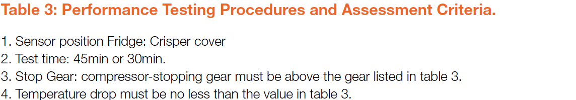
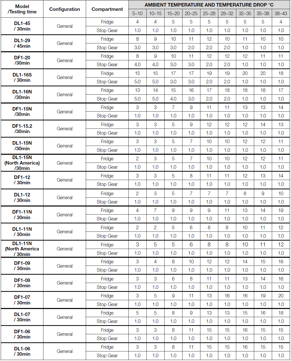
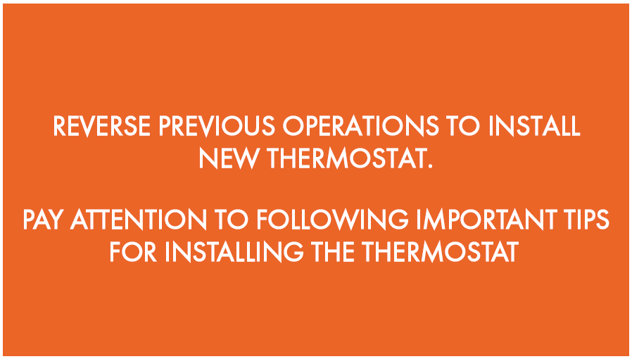
PROCEDURE 1
NOTE
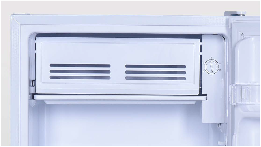
TYPE 1
If you have a top thermostat, please follow procedure below.

TYPE 2
If you have a side thermostat, please go to link
TYPE 3
If you have a thermostat on the side of evaporator, please go to link
TYPE 4
If you have a thermostat in the compressor niche, please go to link.

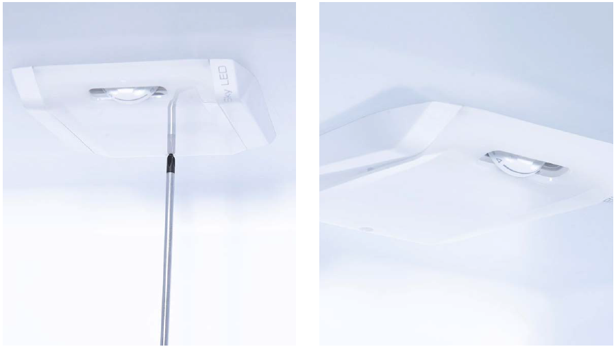
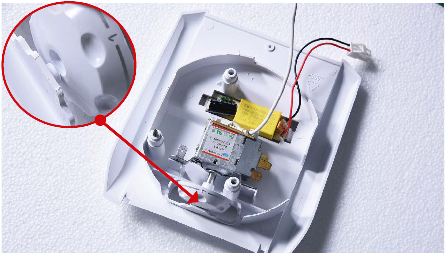
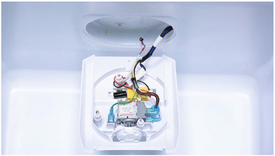
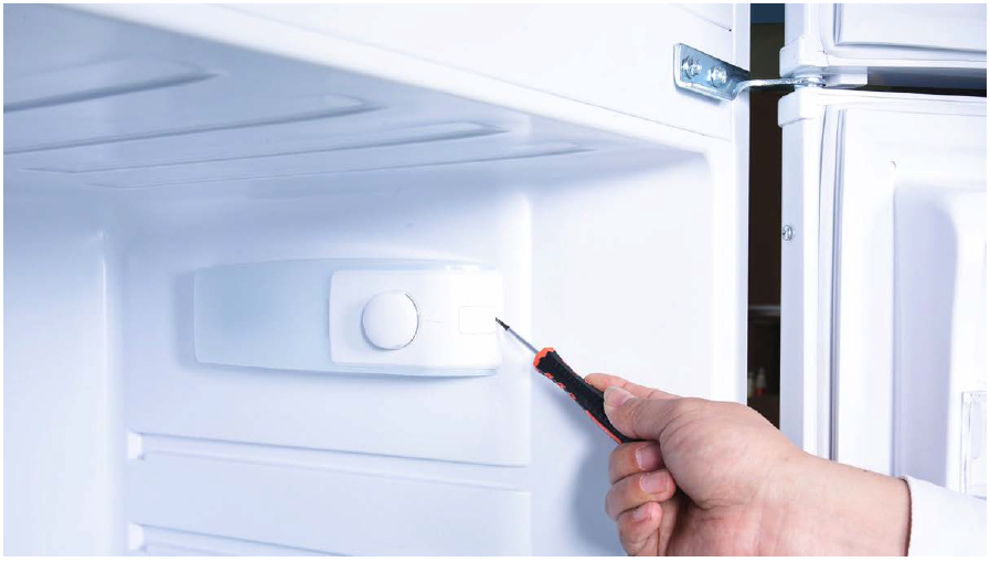
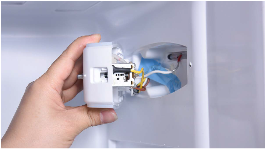
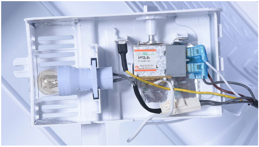
TOP THERMOSTAT
Step 1
Unscrew LED cover.
Step 2
Remove LED cover.
Step 3
Unscrew thermostat cover.
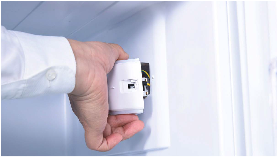
Step 4
Lever off the buckle and push the thermostat out.
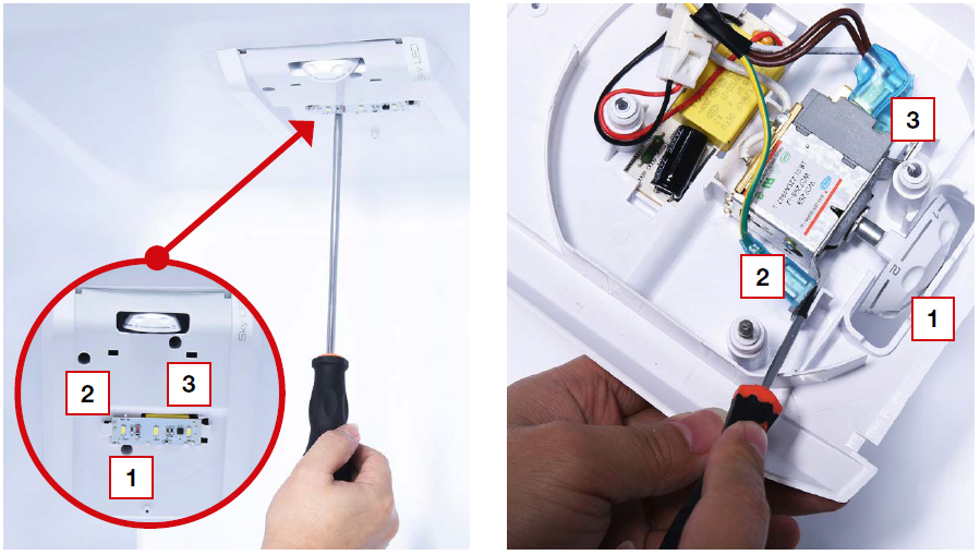
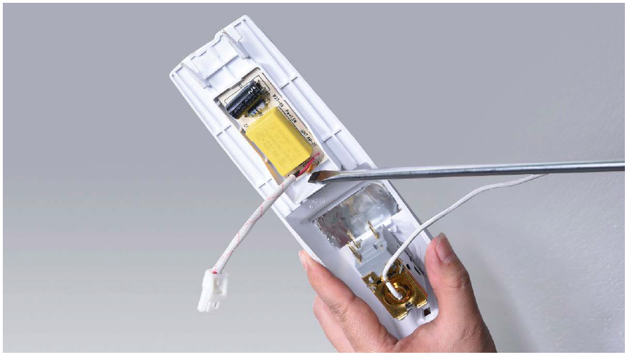
Step 5
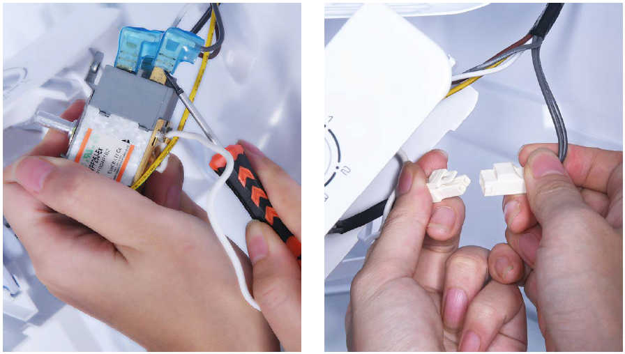
Disconnect terminal for LED.
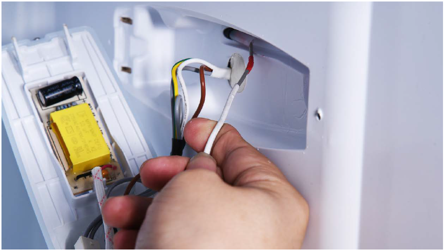
Step 6
Disconnect terminal for thermostat.
Step 7
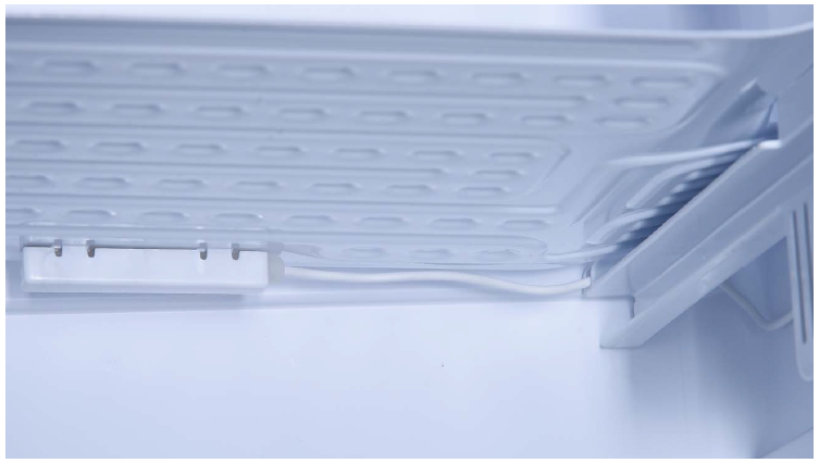
Pull capillary out from hole.

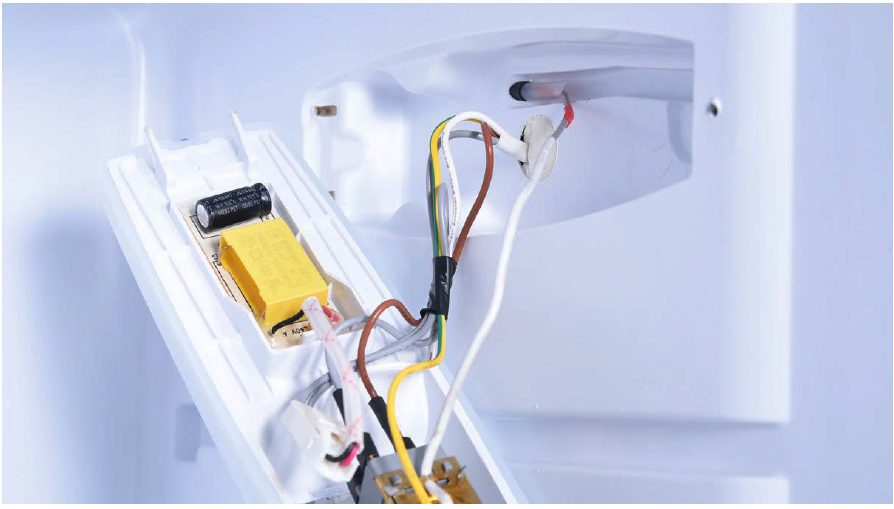
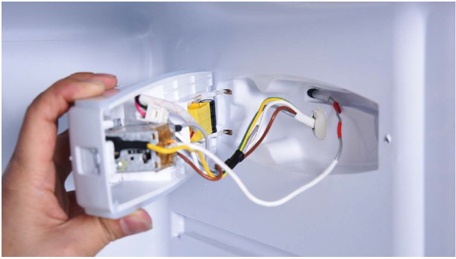
Tips 1:
When inserting capillary into the hole, make sure the first red mark goes in the hole, but second one remains outside of the hole.
Tips 2:
When inserting thermostat into the buckle, please push the control knob into the buckle first.
Tips 3:
Make sure wires are twisted around screw
pole to avoid damaging wires with screw.
SIDE THERMOSTAT
Step 1
Lever off the screw cover.
Step 2
Unscrew.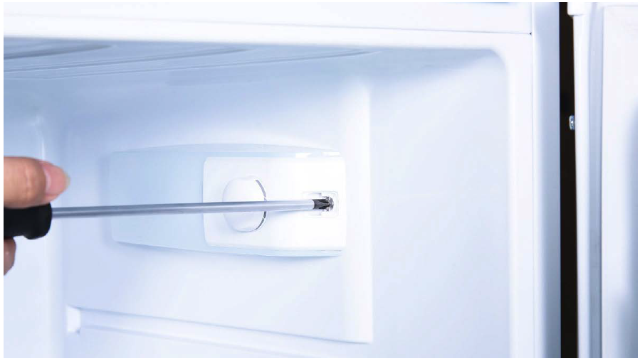
Step 3
Remove thermostat cover.
Step 4
Pull capillary from the hole.
Step 5
Lever off the knob.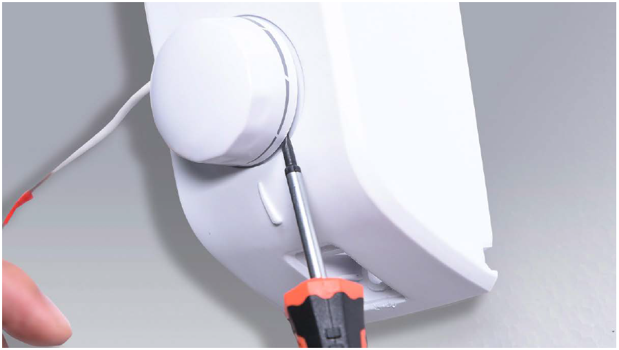
Step 6
Unscrew the nut.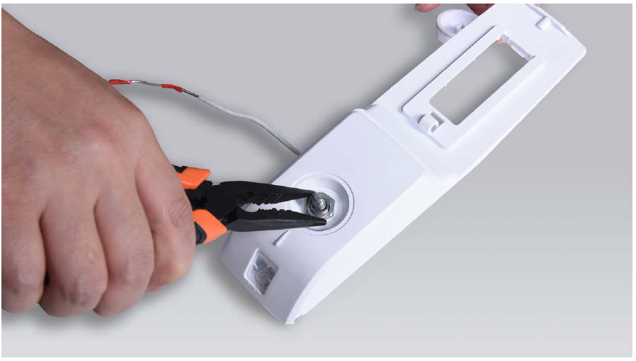
Step 7
Lever off buckle to loosen the LED.


Tips 1:
When inserting capillary into the hole, make sure the first red mark goes into the hole, but second one remains outside of the hole.
Tips 2:
Make sure pins of thermostat cover are properly inserted into the holes.
Tips 3:
Make sure wires are pushed into cavity for thermostat.
THERMOSTAT ON THE
SIDE OF EVAPORATOR
Step 1
Lever off the screw cover.
Step 2
Gently bend the door and remove the buckle
from the groove, and remove the ice-box door.
Step 3
Remove the water tray.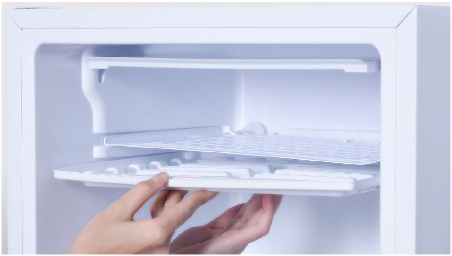
Step 4
Unscrew the screw.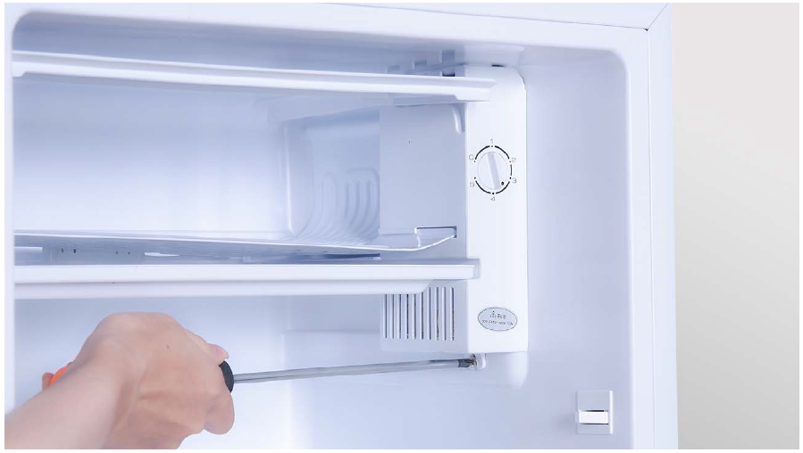
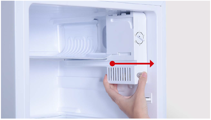
Step 5
Push the thermostat box forward, remove the box.
Step 6
Remove the knob.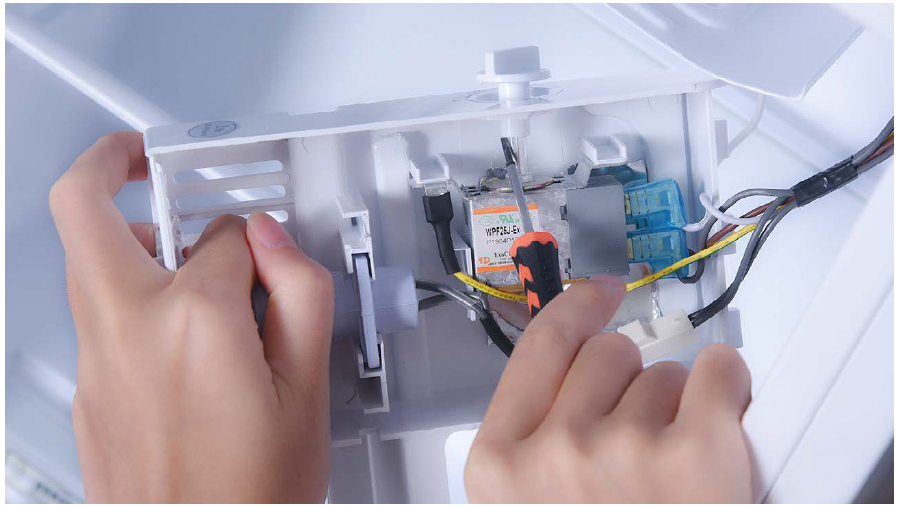
Step 7
Prize up the thermostat.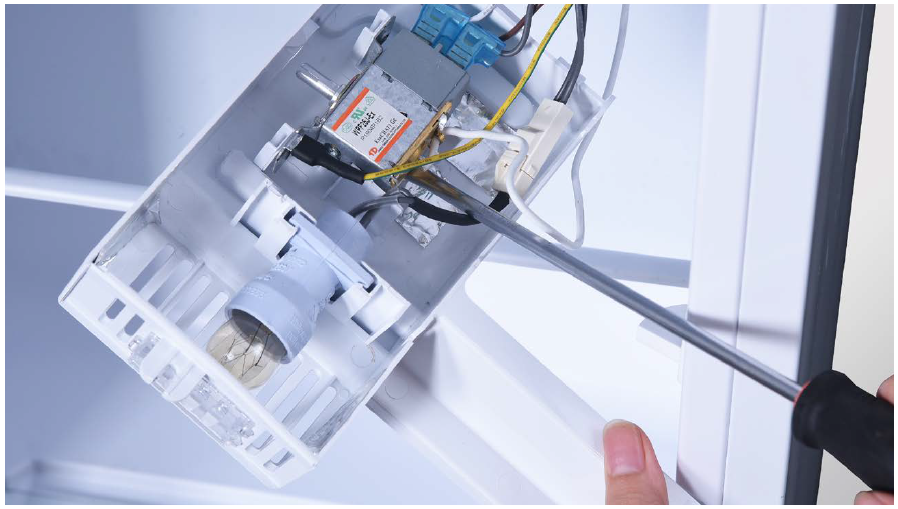
Step 8
Disconnect terminal for thermostat.
Step 9
Disconnect terminal for LED.

Tip 1
When inserting capillary into the hole, make sure the bulb of thermostat is in final position.
Tip 2
Make sure the wires are placed into cavity of thermostat.
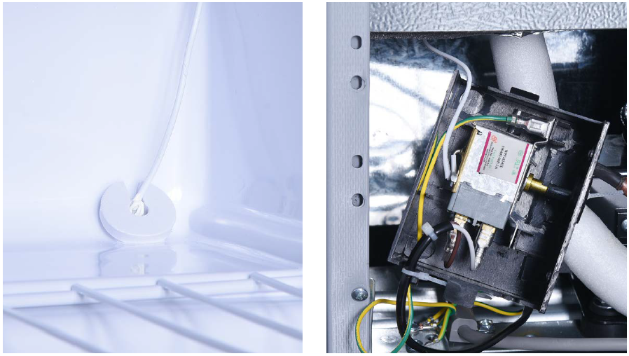
THERMOSTAT IN COMPRESSOR NICHE.
Step 1
Unscrew.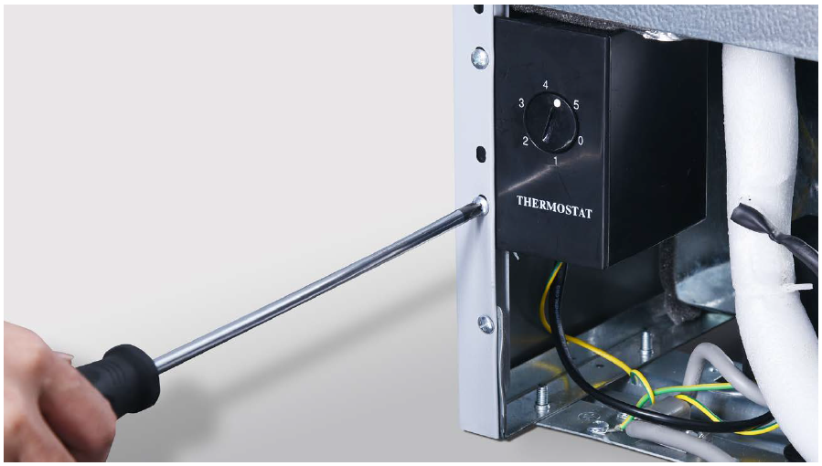
Step 2
Remove thermostat box.
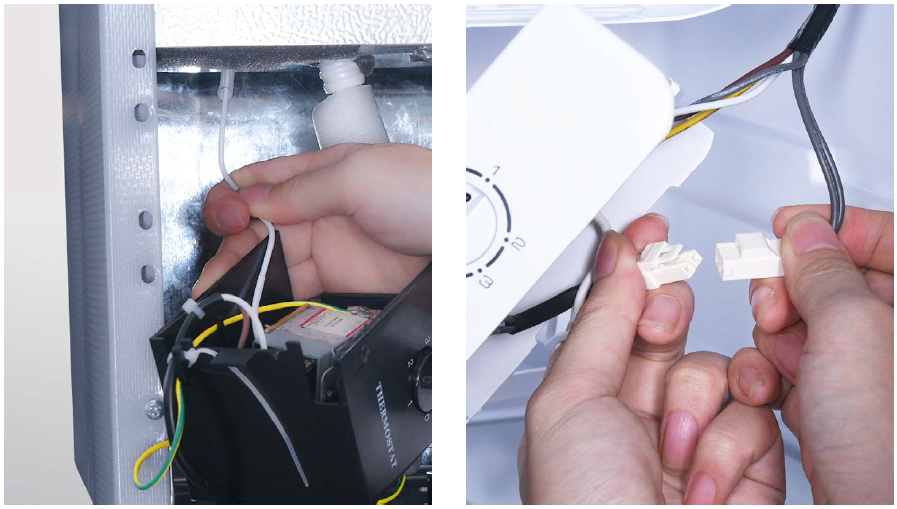
Step 3
Prize up thermostat knob and remove.
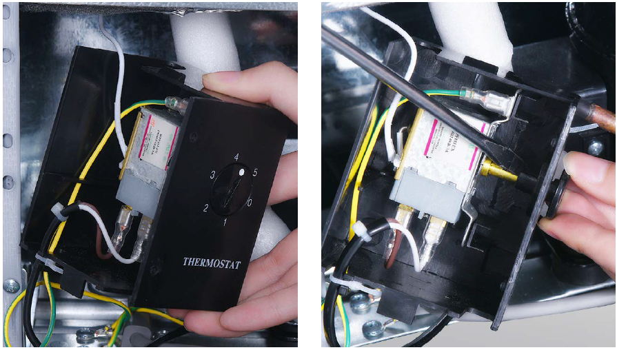
Step 4
Prize up the thermostat.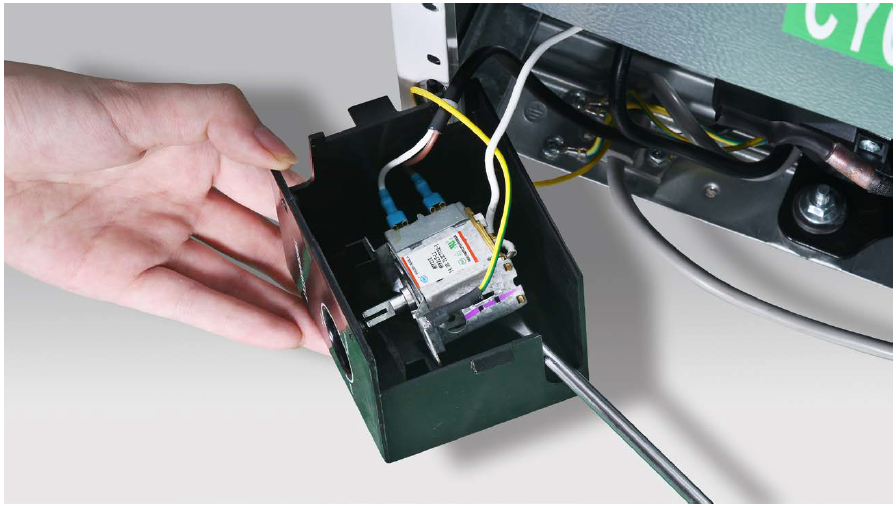
Step 5
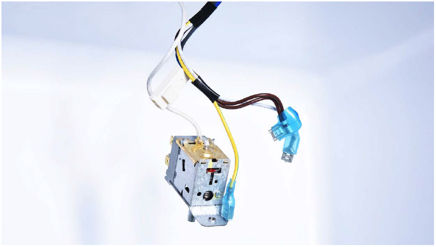
Pull capillary out from the foam.
Step 6
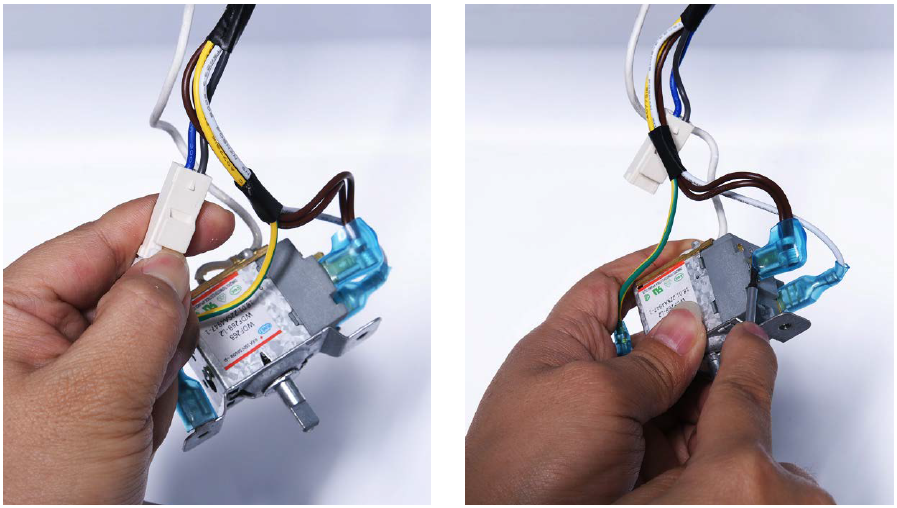
Disconnect the terminal.
Tip 1
When inserting capillary into the hole, make sure the bulb of thermostat is in final position.
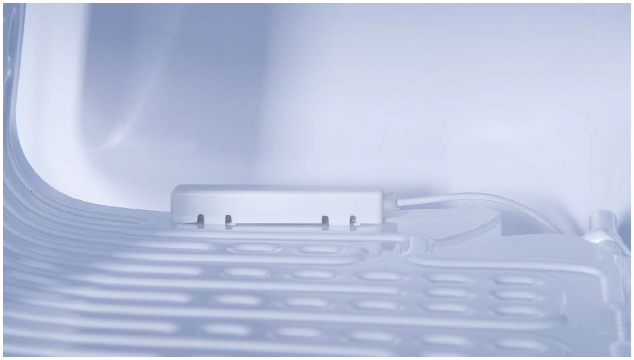
Tip 2
When inserting thermostat into the hole, please verify that the seal of the hole is good.
Tip 3
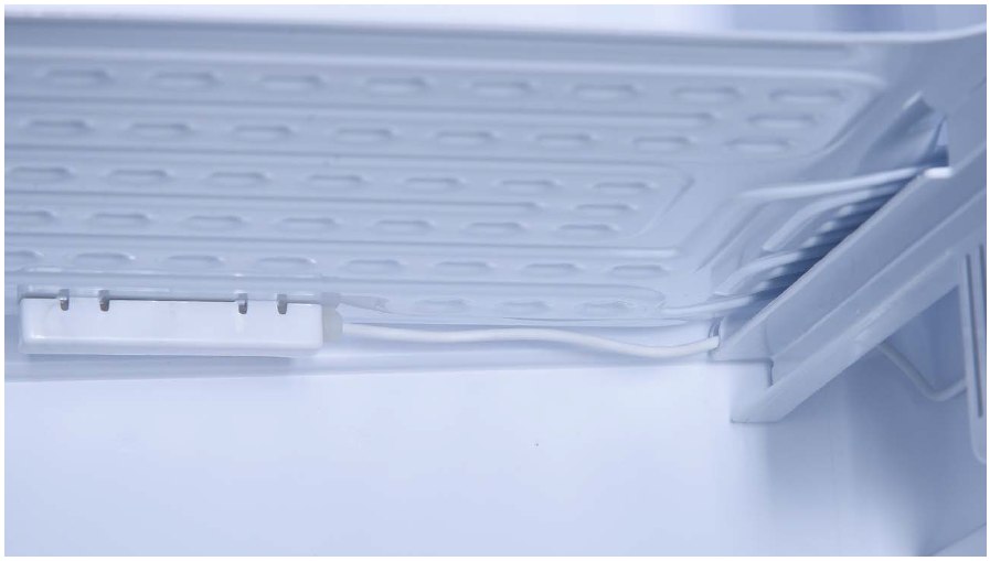
Don’t forget to put the wires in the right position and attach a cable tie.

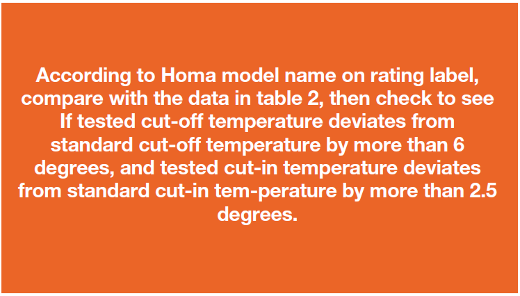
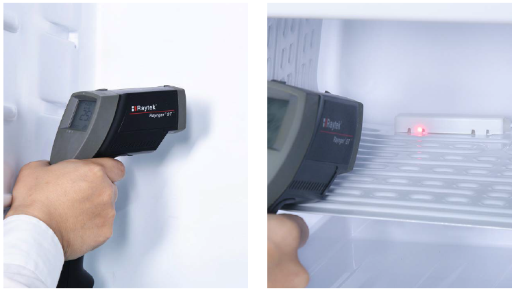
CHECK AND TEST 3
Step 1
Set thermostat control knob to gear Min, and switch on the appliance.
Step 2
According to model name in rating label, study diagram below to find position of thermostat bulb.
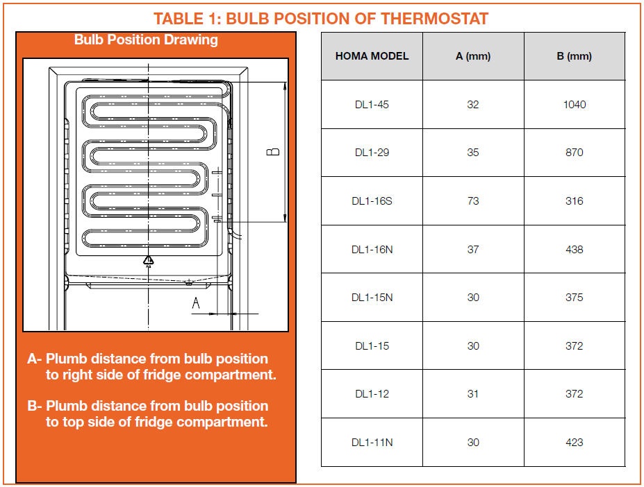
Please find out the bulb position of thermostat on
the surface of evaporator.
Step 3
Perform following 2 tests:
1. When compressor stops for second time, measure temp. in the area near the thermostat bulb.
2. When the compressor
starts again, measure temp. in the area near the thermostat bulb.
DIAGNOSIS 4