


CHECK AND TEST 1

Step 1
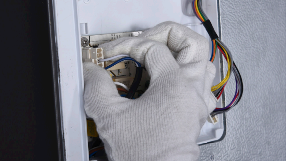
Unscrew cover of mainboard with a Cross-head screwdriver
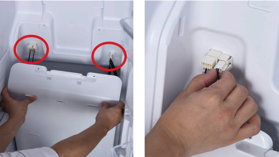
Step 2
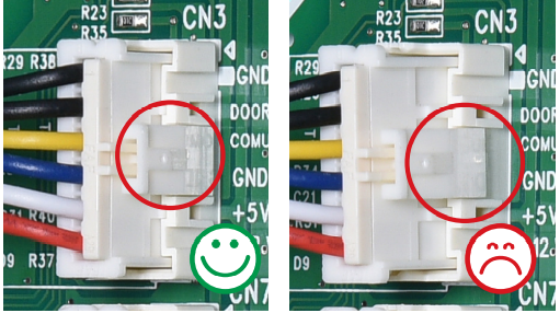
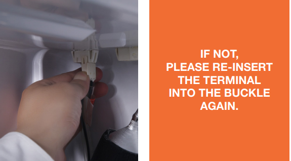
Check if terminal in PCB area is pushed to final position. If not, reinsert it to final position.
Step 3
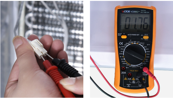
Set multimeter to
resistance gear. 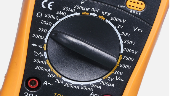
Step 4
PCB area, measure the
resistance of defrost temp.
sensor with a multimeter.

Step 5
Take note of value.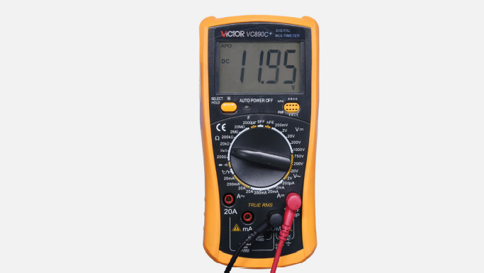
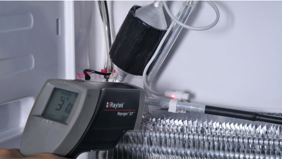
Step 6
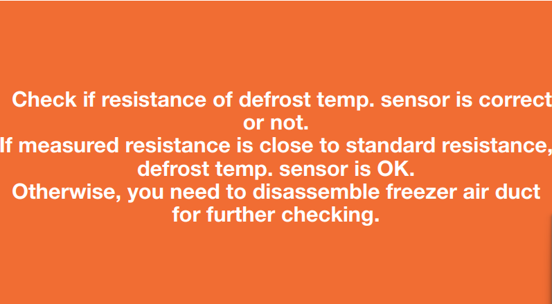
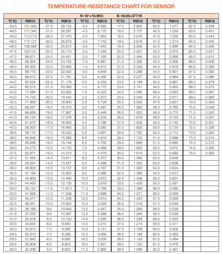
Measure the temperature of freezer air duct, near the defrost temp. sensor. Use measured temperature to find the standard resistance value in Temperature-Resistance Chart for Sensor.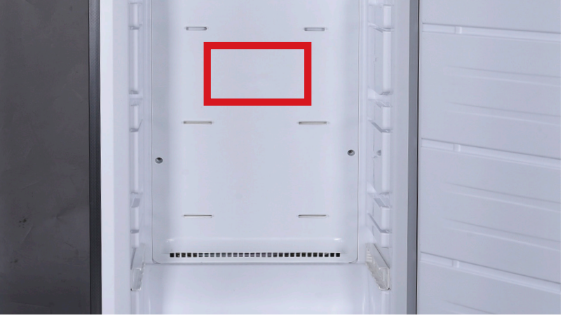

DIAGNOSIS 1

PROCEDURE 1
Disconnect the terminalfor display panel.

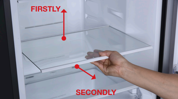
Step 1
Remove
all shelves.
Step 2
Remove upper drawers.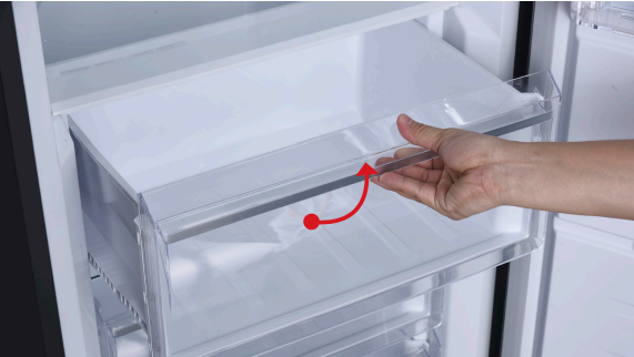
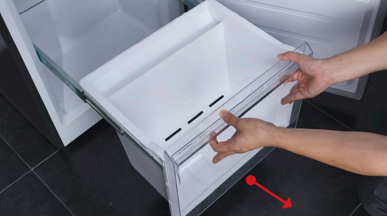
Step 3
Remove bottom drawer
Step 4
Remove drawer cover.
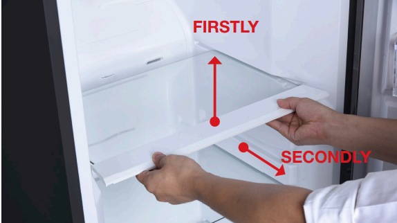
Step 5
Remove glass shelves
under drawers. 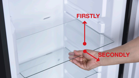
Step 6
Prize off the decorative
panel and take if off. 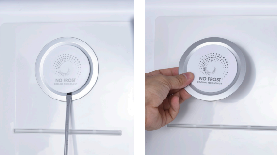
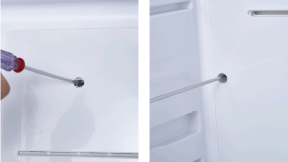
Step 7
Unscrew the upper air
duct.
Step 8
Pull outward and take off
the upper air duct 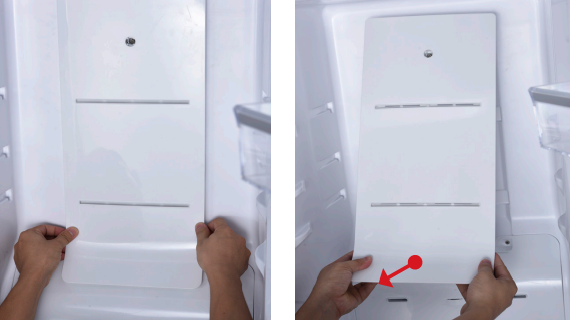
Step 9
Unscrew the lower
airduct. 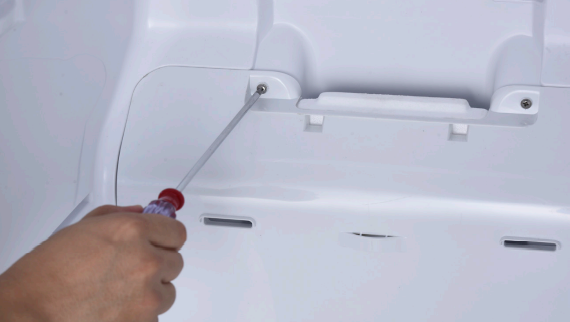
Step 10
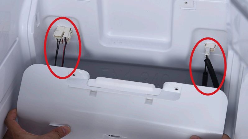
Disconnect the
connectors between
airduct and cabinet
Step 11
Remove the lower air
duct. 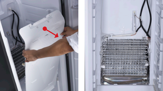

CHECK AND TEST 2
Step 1
Check if terminal is pushed properly into final position.
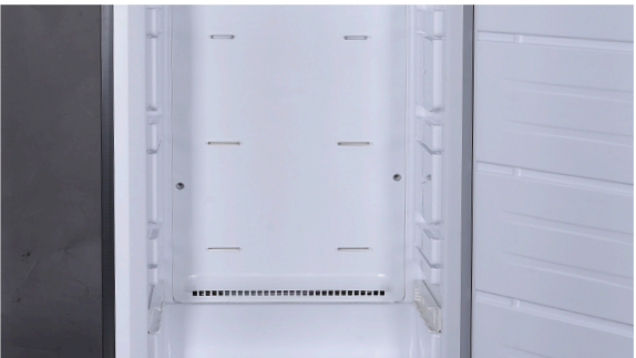
Step 2
Check if sensor is
attached in proper
position, as shown in
picture.
If not, correct it. 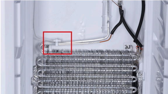
Step 3
Check if wire of defrost
sensor is broken.
If yes, replace it with a
new one.
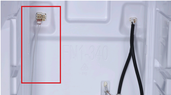
Step 4
Disconnect terminal of
defrost temp. sensor.
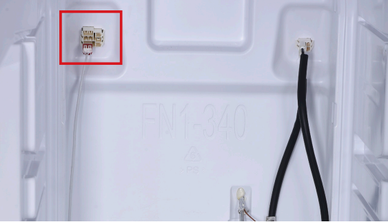
Step 5
Check if the terminal is
stuffed with foam. 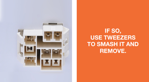
Step 6
Measure resistance of
defrost temp. sensor
from terminal in freezer,
and take note of it.
Step 7
Measure the temperature of defrost temp. sensor.

DIAGNOSIS 2

CHECK AND TEST 3
Step 1
Set multimeter to resistance gear.
Step 2
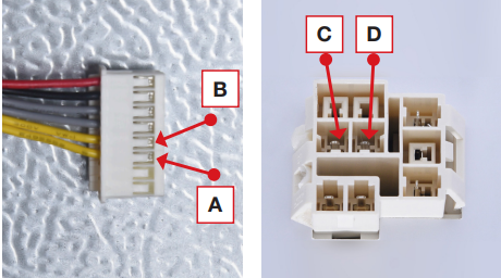
Put detector into one end of wires in PCB area. Put another detector into end of wires behind air duct.

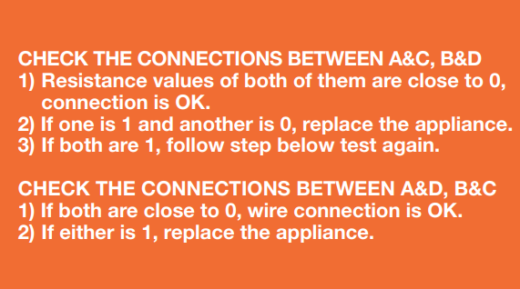
DIAGNOSIS 3


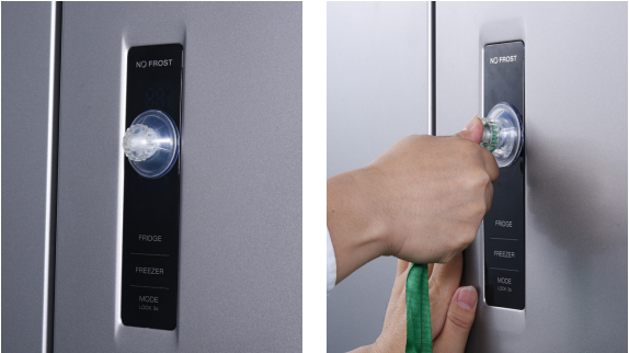
PROCEDURE 2
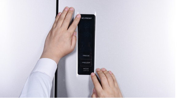
Step 1
Push a 6mm sucker onto display and turn the knob to strengthen suction force.
Step 2
Wrap a belt around knob to make it easier to pull out of display board.
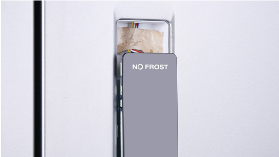
Tips for installing display.
Tip 1
After connecting terminal, please use tape to fasten wires to avoid crushing with cover.
Tip 2
After putting display into cavity, press edge until you hear a clicking sound, this means the board is pushed into final position
Tip 3
Please press all buttons on display board to make sure it works well.

PROCEDURE 6
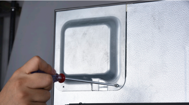
Step 1
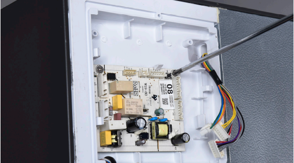
Unscrew cover of mainboard with a Cross-head screwdriver.
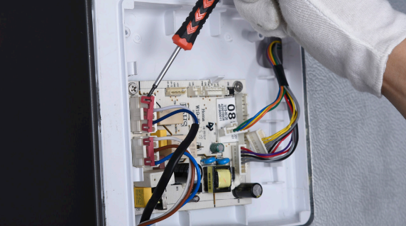
Step 2
Prize off the connector buckles.
Step 3
Disconnect the connectors.
Step 4
Unscrew the mainboard.
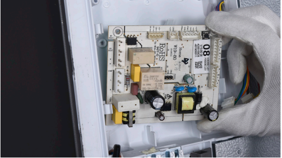
Step 5
Prize off the buckle to remove mainboard.
Reverse steps above to install a new mainboard.

DIAGNOSIS 4


PROCEDURE 5
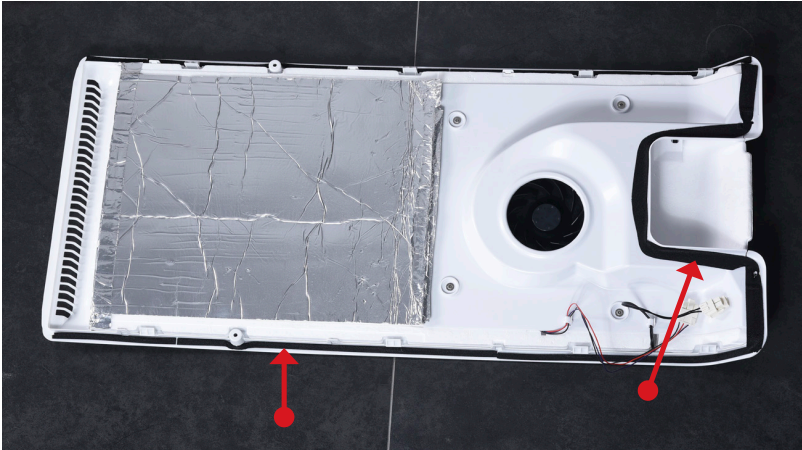
Tip 1
Make sure the sealing sponges are in good condition.
Tip 2
When reinstalling the air duct, fasten the wires to avoid crushing with air duct.
Tip 3
Check to see if there is a wide gap between air duct and cabinet. If there is, reinstall air duct.

GO BACK TO COMPONENT LIST