

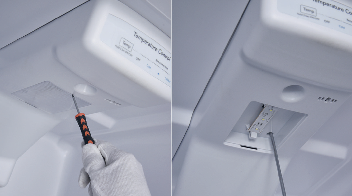
Step 1
Unscrew the screw of fridge air duct.
Step 2
Remove the LED lamp cover and the screw.
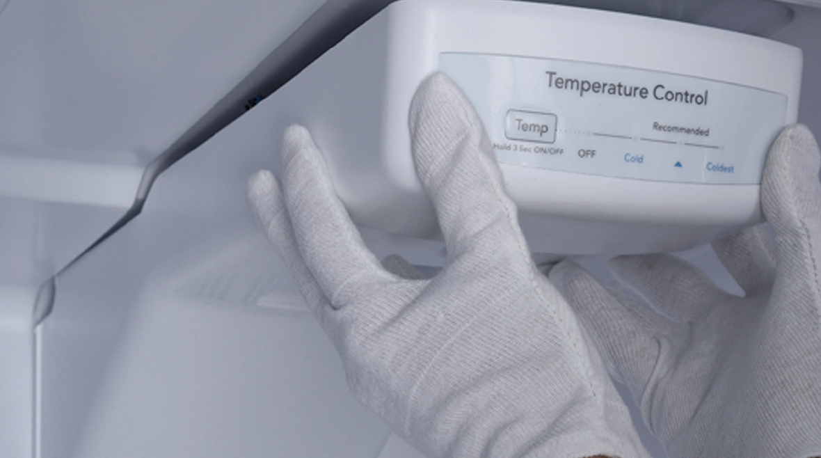
Step 3
Remove the air duct.
Step 4
Unplug the electrical wires.
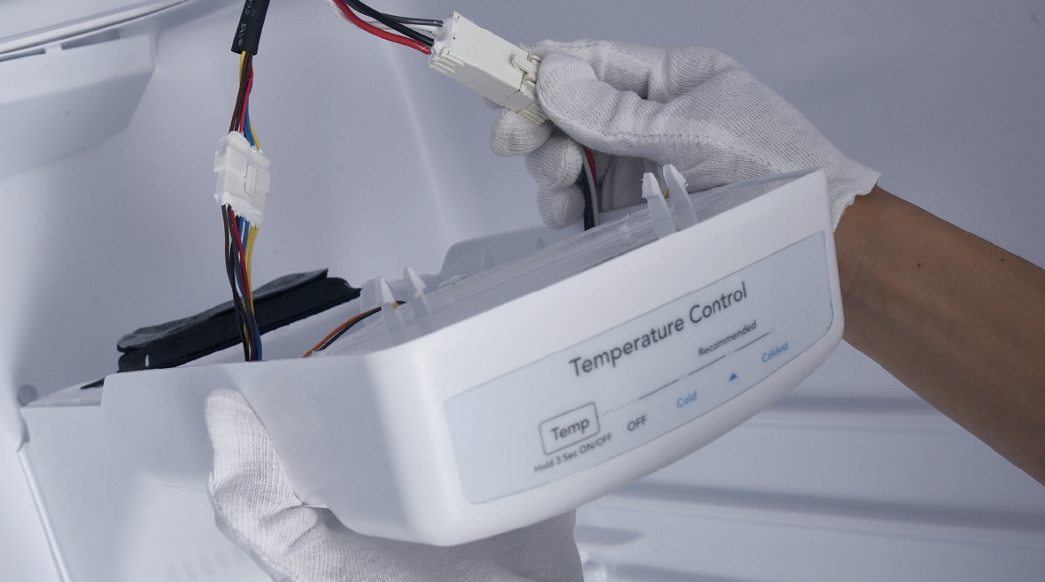
Step 5
Disconnect the terminal of potentiometer.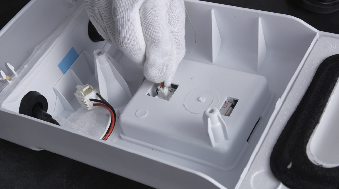
Step 6
Remove the UI film.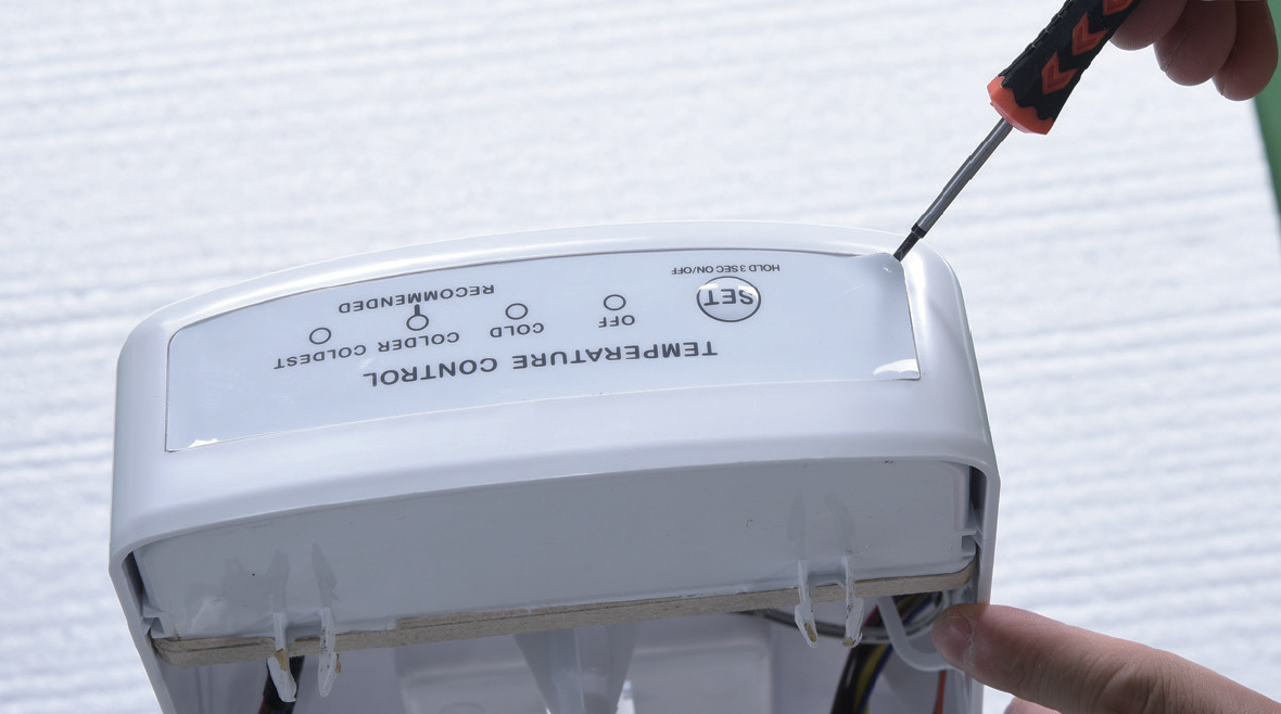
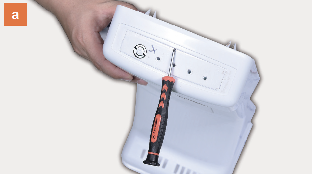
Step 7
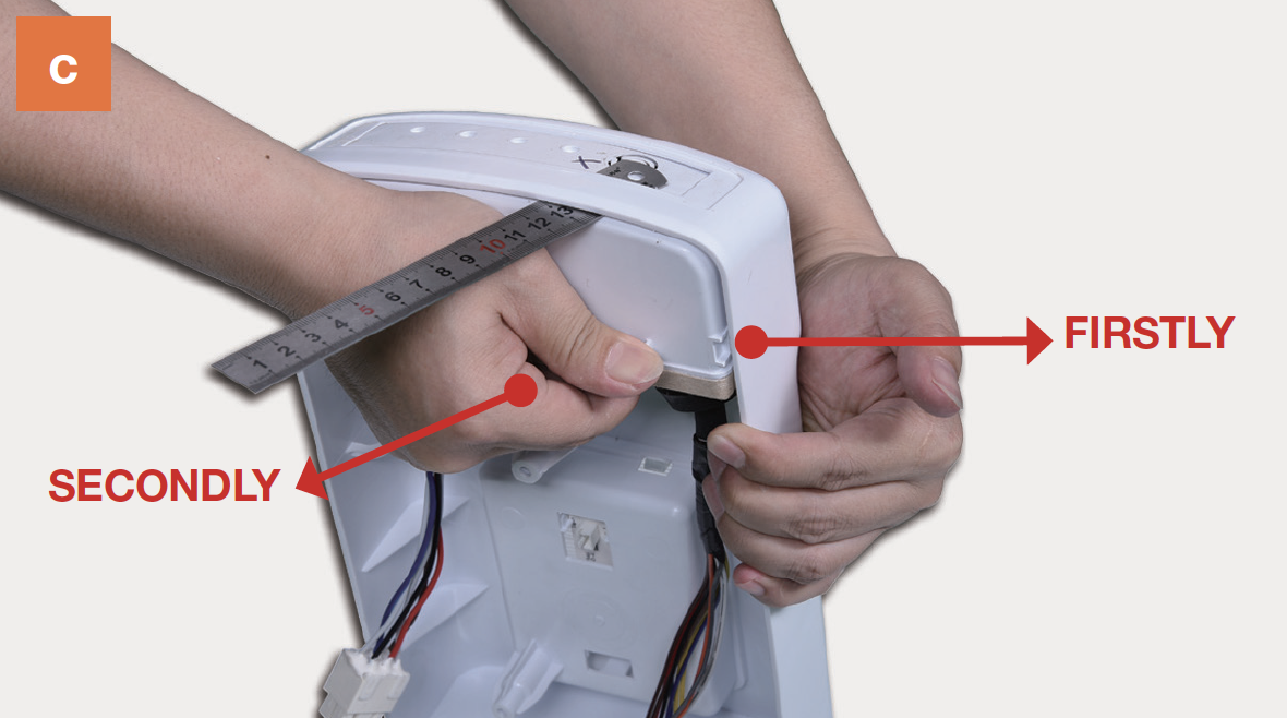
Remove PCB box from air duct.a) Use 2 mm slot screw driver to create a gap in front side.
b) Insert a steel ruler to even the gap.
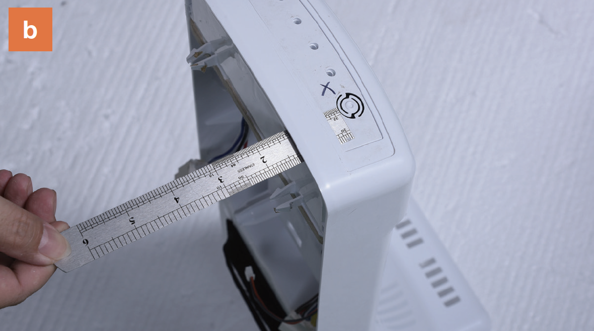
c) Pull the PCB box out.
Step 8
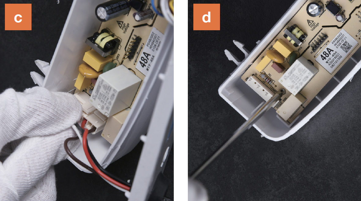
Disassemble PCB box.a)Prize off the buckle;
b) Remove the cover;

c) Disconnect the terminals;
d) Unscrew and remove the PCB;

CHECK AND TEST 1
Step 1
Reconnect the main control board to the cable.

Step 2
Reconnect the electrical wires.

Step 3
Heat fridge temp. sensor.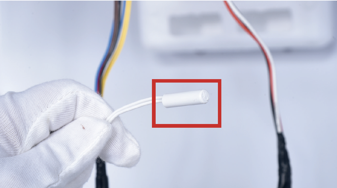
Step 4
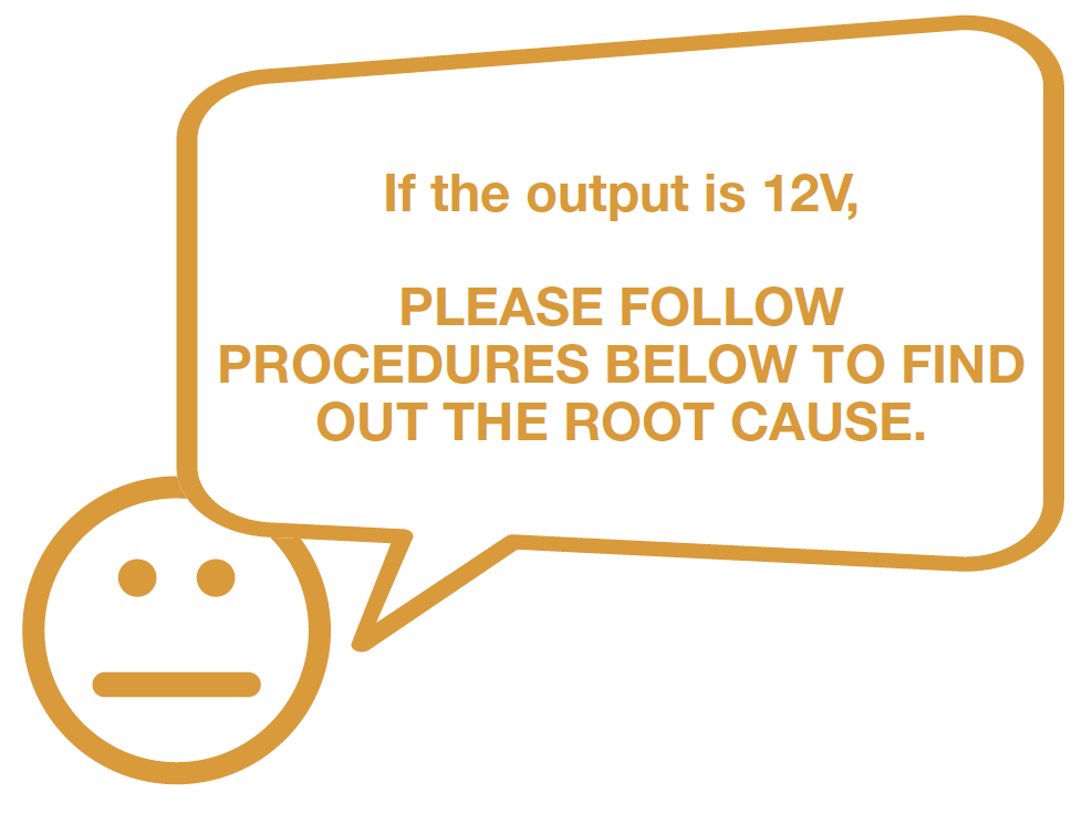
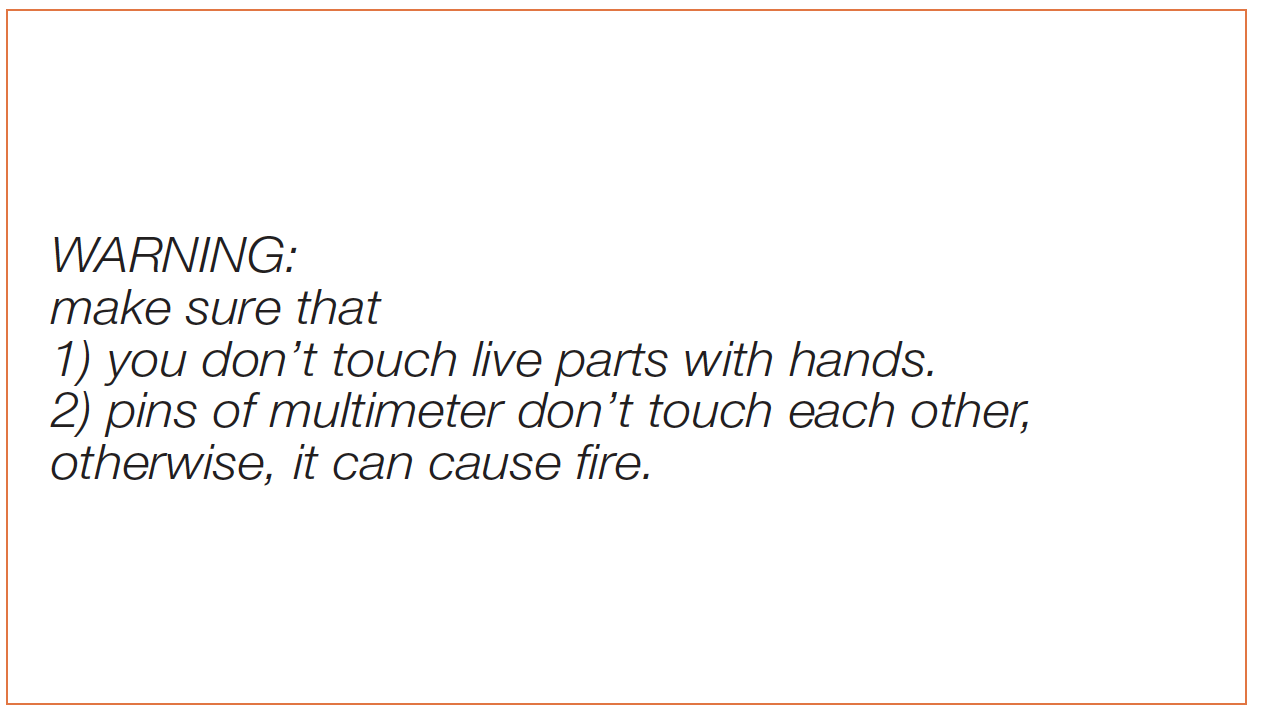
Use multimeter to test the voltage of output for“FAN+” & “GND”. Note: Make sure that the
terminal is connected when you do the test.

Step 5
Take note of test result.

DIAGNOSIS 1


CHECK AND TEST 2
Step 1
Press LED switch and hold on, then press the
button on mainboard for 3 seconds to start
manual defrost.

Step 2
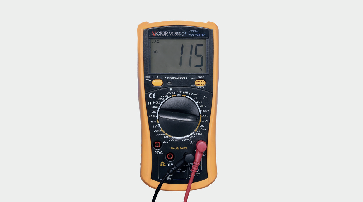
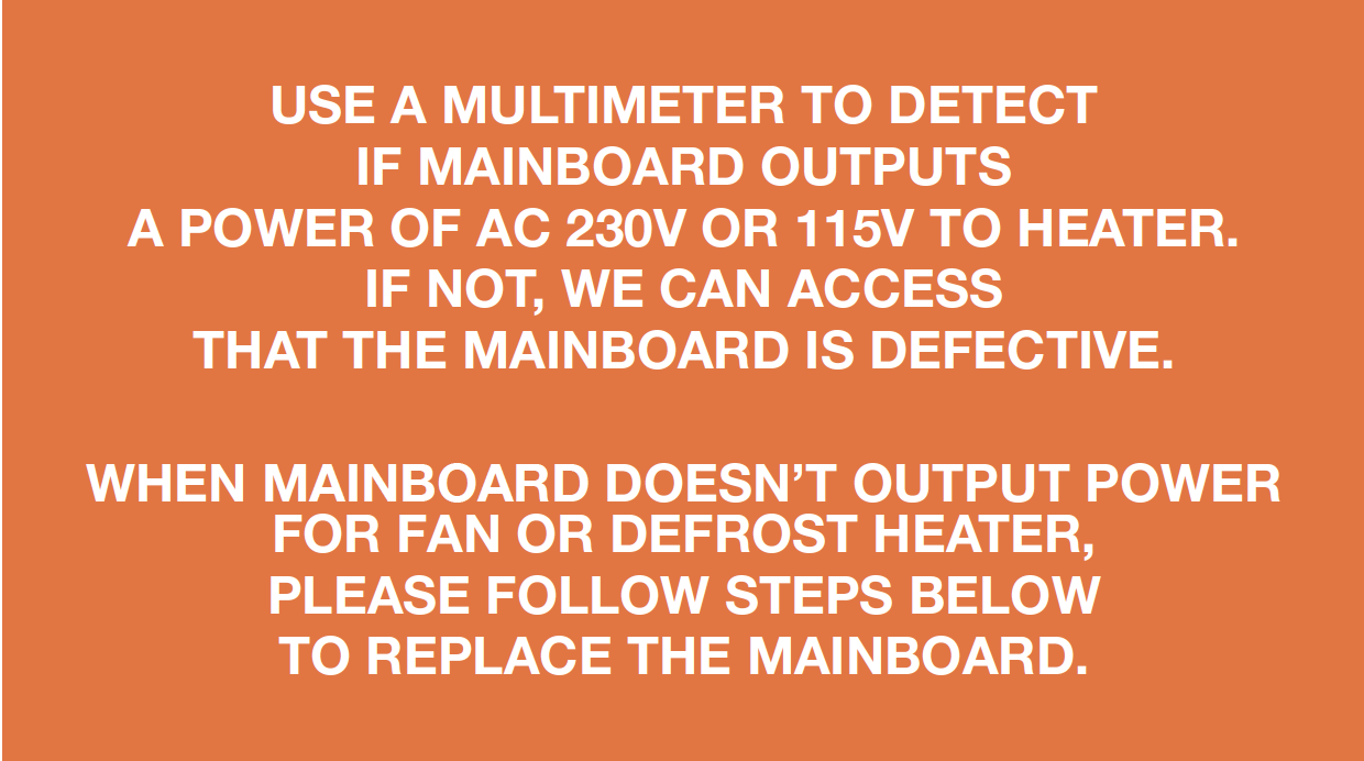
Test voltage of terminals for defrost heater.
Please keep all terminals connected with
mainboard, otherwise, mainboard cannot
output power to heater.

Step 3
Take note of the result. Later power off to quit
manual defrost.
The value should be 230V or 115V.

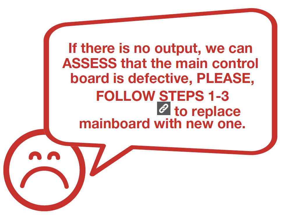
DIAGNOSIS 2

DIAGNOSIS 3

PROCEDURE 2

GO BACK TO COMPONENT LIST